This chapter explains in detail all of the commands in the menus and the functionality of the gizmos. You'll also find pictures of each of the gizmos.
The drawing window is the main IRIS Showcase window. It is the area in which you draw objects, type text, and build 3D models.
A ruler appears along the top and left edge of the drawing window. These rulers help you draw objects of a particular size and position objects on the page. Additionally, the ruler along the top lets you set margins, indents, and tabs in Text objects. See “Setting Text Margins”, “Indenting Text”, and “Setting New Tab Stops”
If a page is too large to display in the window, the scroll bars along the right and bottom edge of the window become active. Use these to change the portion of the page you are viewing. See also “Changing the Portion of the Page You Are Viewing (Panning)”
The File menu holds all the commands for manipulating files—opening them, saving them, inserting them, and printing them. Additionally, you'll find the “Set Preferences...” and “Quit” commands in this menu.
The “New” command closes the file you're working on and opens a new file. If you have changed the file you're working on, a dialog box pops up asking if you want to save the changes before quitting. To save the changes click Save; to erase them click Discard; to cancel the operation, click Cancel.
The “Open” command opens an existing file. Select “Open” and the File Browser appears. If you have changed the file you're working on, a dialog box pops up asking if you want to save the changes before opening another file. To save the changes click Save; to erase them click Discard; to cancel the operation, click Cancel.
See also “Opening IRIS Showcase Files”
The “Re-open” command keeps a list of files you have opened since last starting the application. Select a file from the rollover menu and IRIS Showcase opens that file and closes the one on which you are working. If you select “Re-open” without going to the rollover menu, you go to the last file you visited. You can open a file and automatically put others on the Re-open list by typing the following from a shell:
showcase file1 file2 file3 file4
IRIS Showcase opens file1 and places file2, file3, and file4 on the Re-open list.
See also “Working with Multiple Files”
The “Insert” command provides a rollover menu that lets you insert a variety of files into your IRIS Showcase document. You can insert:
an IRIS Showcase file using “Showcase...”
an image using “Image...”
an audio file using “Audio...”
a 3D model using “3D object...”
an EPS file using “EPS...”
a PICT file using “PICT...”
a Rich Text Format file (RTF) using “RTF...”
an ASCII text file using “Text...”
If you don't select a command from the rollover menu, IRIS Showcase assumes you are importing another IRIS Showcase file.
The “Save” command does just that—saves your file. If you are saving a file for the first time, and you haven't yet named it, the File Browser appears.
| Tip: <Alt>-s |
“Save As” is a rollover menu that lets you rename a file, or save it as a particular file type.
“...As” lets you save a file under a new file name. (You get this if you choose “Save As” without going to the rollover menu.)
“...As Template” lets you save the file as a template. A template is simply a one-page file that you can use to regulate the format of your documents.
“...As Mailable File” lets you save an IRIS Showcase file so that it can be inserted into mail messages.
“...As Text File” lets you save the contents of a Text object. You must select or be editing a Text object. If you select a Text object, all of the text in that block is saved in an ASCII text file. If you edit a Text object, the selected characters are saved. If you haven't selected any characters, IRIS Showcase saves all of the text in that block.
“...As PostScript” saves the file as PostScript so it can be viewed using the PostScript viewer and printed using lp or lpr.
“...As EPS” lets you save selected objects, or the page, as Encapsulated PostScript (EPS). This allows you to bring it into other programs that accept EPS files.
“...As 3D (Inventor)” lets you save selected 3D models in the Inventor file format. If you select a 3D container, the entire scene is saved; if you edit a 3D container, the selected models are saved. If you haven't selected any models, IRIS Showcase saves the entire scene.
See also “Saving Files” and Appendix C, “Importing and Exporting Files.”
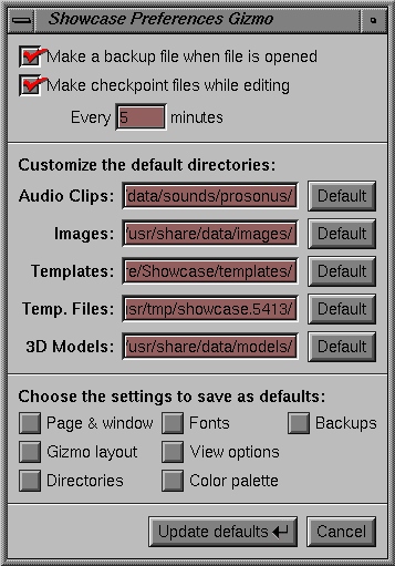
The “Set Preferences...” command opens the Preferences gizmo, shown in Figure 11-1. This gizmo lets you change some of the program's default settings. Set the preferences; then press the Update defaults button.
The top of the Preferences gizmo contains two buttons.
“Make a backup file when file is opened” tells IRIS Showcase to create backup files every time you open an IRIS Showcase file.
“Make checkpoint files while editing” tells IRIS Showcase to save a copy of your file after a certain number of minutes. Specify how often IRIS Showcase saves the file by typing a number in the box that appears.The default setting is five minutes. (See also “Having IRIS Showcase Automatically Create Backup Files”.)
The middle of the gizmo shows the default directories in which IRIS Showcase looks for or places certain types of files. You can specify a different directory by typing a new pathname in the editable field. To return to the default setting, click the Default button next to the editable field.
| Note: Click the box next to the label “Directories” if you want to save these settings and use them every time you use IRIS Showcase. |
The bottom of the gizmo contains a collection of buttons.
“Page & window” saves your current page size and position on the screen and makes it the default. All new IRIS Showcase files will come up with this as their page size.
“Gizmo layout” saves the current gizmo display. By default, IRIS Showcase opens the Master gizmo when it starts and places it next to the drawing area. You can change this so IRIS Showcase places the Master gizmo somewhere else, or automatically displays other gizmos when it starts.
In the middle of the gizmo, you specify which directories you want IRIS Showcase to search in for certain types of files. “Directories” lets you save these settings as your default.
“Fonts” saves font information—the family, the size, and the style. IRIS Showcase uses this font setting unless you specify otherwise.
“View Options” saves settings on the “Circle/Arrow Options” form and saves the settings in the View menu.
“Color Palette” saves the color palette. Choose this if you've added new colors to the palette, and want to replace the default color palette with your current one.
At the top of the Preferences gizmo, you turn backups and autosave on and off for a particular session. “Backups” saves that setting as your default.
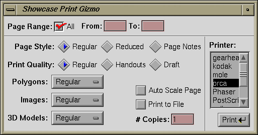
The “Print” command opens the Print gizmo, shown in Figure 11-2. This gizmo lets you print a copy of your current file to a selected printer. See also “Printing an IRIS Showcase File”
“Page Range” lets you specify the pages to print. Click the box next to “All” to print all the pages; type the page range in the empty fields to select a range of pages.
“Page Style” gives you three printing options: “Regular,” “Reduced,” and “Page notes.” “Reduced” prints four pages per sheet of paper; “Page notes” prints the page notes, each of which includes a reduced version of the original page.
“Print Quality” gives you three options: “Regular,” “Handouts,” and “Draft.”
Images and 3D models print slowly. Choose “Draft” if you want to convert all images to black and white and convert 3D models into wireframe representations.
People often create presentations that have light text on top of a solid, dark background. To get a printed copy that is legible, choose “Handouts.” Solid polygons are drawn with only an outline and text is darkened. This is useful if you want to create a handout of your presentation.
Use the pop-up menus next to the labels “Polygons,” “Images,” and “3D Models” if you want to adjust the settings manually. For example, use the pop-up menus if you want to specify different quality levels for each object type or if you want to print placeholders for the polygons, images, and 3D models.
“# Copies” lets you specify how many copies to print.
“Auto Scale Page” tells IRIS Showcase to condense the page so all of the objects fit onto the printed page. IRIS Showcase looks at the page size and determines which orientation to use: landscape (11 by 8.5) or portrait (8.5 by 11).
“Print to File” creates a PostScript file that contains the range of pages and quality levels you specified in the Print gizmo.
The “Quit” command closes the file you're working on and quits from the application. If you have changed the file you're working on, a dialog box pops up asking if you want to save the changes before quitting. To save the changes click Save; to erase them click Discard; to cancel the operation, click Cancel.
The Edit menu holds many of the commands for modifying objects.
The “Undo” command lets you undo the changes you make. For example, suppose you change the color of a circle from black to red. Select “Undo” and the circle becomes black again. You can choose “Undo” multiple times to reverse a sequence of changes.
The “ Redo” command works with the “ Undo” command. For example, suppose you change the color of a circle from black to red. Select “Undo” and the circle becomes black again; select “ Redo” and the circle becomes red again.
IRIS Showcase lets you edit individual elements of an object—letters and words in Text objects, points in a Graphics object, and models in a 3D container. To do so, you select an object; then choose the “Edit Object” command. The object is ready to be edited when it is surrounded by a light-green box. When you're editing an object, the menu choice changes to “Done Editing.” Choose this when you are finished editing the object.
See also “Editing Objects”.
The “Delete” command is equivalent to the <Back Space> or <Delete> key on the keyboard. It removes selected objects from the page. You cannot paste objects that have been deleted using this command. If you want to delete an object and paste it elsewhere, use the “Cut” command.
See also “Deleting Objects”.
The “Cut” command removes selected objects, text, or models from the page and places them in a cut buffer. Use the “Cut” command when you want to delete objects from a page or move an object to another page or document.
To cut an item, select it, then choose “Cut” from the menu. Use the “Paste” command to replace an item you've cut. See also “Deleting Objects”.
The “Copy” command makes a copy of selected items and places it in a buffer. Use the “Copy” command when you want to duplicate objects or text or want to copy the style of an object. For instance, suppose you want all the subheadings in your report to be Helvetica 18, bold, italic, and blue. You can create one paragraph in this style; then copy the style and paste it to the other subheadings.
See “Copying and Pasting Objects”, “Copying and Pasting Text”, and “Copying and Pasting 3D Models”
The “Paste” command retrieves the item in the cut buffer and pastes it onto your page. If you paste text into a Text object you're editing, the text is inserted at the cursor location. If you paste a 3D model into a 3D container you're editing, a red outline of the model appears inside of the container; otherwise, a red outline of the object appears on the page. Move the outline around until it's in the location you want; then click once with the left mouse button. The object appears. You can continue pasting as many times as you want.
The “Duplicate Paste” command is a slight variation of the “Paste” command. Use it to create a row of objects uniformly spaced. To use “Duplicate Paste,” first paste an item you've cut or copied. Then choose “Duplicate Paste.” Another copy of the object is pasted, and it's offset by the same amount.
The “Paste Attributes” command works in conjunction with the “Copy” command. Use it when you want to copy the style of an object. For instance, suppose you want all the subheadings in your report to be Helvetica 18, bold, italic, and blue. You can create one paragraph in this style; then copy the style and paste it to the other subheadings.
The rollover menu lets you specify which style to paste:
Select “Drawing” and you can copy the style of a 2D graphics object—color, pattern, and line style.
Select “Font” and you can copy the style of a particular word or words—font, size, style, and color.
Select “Paragraph Style” and you copy the format of a paragraph—the margins, tabs, justification, and leading, or spacing.
Select “Hyperscript” and you paste the hyperscript from one object to another.
The “Select All” command selects all of the objects on a page, all of the words in a Text object you're editing, all of the points in a Graphics object you're editing, or all of the models in a 3D container you're editing.
To select all of the objects on a page, turn to that page, make sure no objects are being edited, and choose “Select All.”
To select all of the words in a Text object, edit the Text object; then choose “Select All.” IRIS Showcase highlights all the words.
To select all of the points in a Graphics object, edit the object; then choose “Select All.”
To select all of the models in a 3D container, edit the container; then choose “ Select All.”
The “Group” command takes all of the selected objects—Text objects, Graphics objects, images, and 3D containers—and turns them into one object. For example, suppose you create a picture out of circles, lines, and squares. Group it and you can move the entire picture—not just elements of it. You can also use this command to group models within a 3D container.
See also “Grouping and Ungrouping Objects.”
The “Ungroup” command splits a group into its original components—individual objects, or other groups. To use this command, select the object you want to ungroup and choose “Ungroup” from the menu. All of the objects that made up the group are selected.
See also “Grouping and Ungrouping Objects.”
The “Pop” command lets you change the way overlapping objects stack on top of each other. To use it, select the object whose stacking order you want to change; then choose “Pop.” It has a rollover menu that lets you specify whether you want the object to pop to the top or just one level. The default behavior is to pop to the top. (You cannot use this command to change the way 3D models are positioned in the 3D container.)
See “Popping and Pushing Objects”.
| Tip:
<Alt>-<Up Arrow> is the keyboard shortcut for
“Pop.” <Alt>-<Shift>-<Up Arrow> is the shortcut for popping one layer. |
The “Push” command lets you change the way overlapping objects stack on top of each other. To use it, select the object whose stacking order you want to change; then choose “Push.” It has a rollover menu that lets you specify whether you want the object to push to the bottom or just one level. The default behavior is to push to the bottom. See “Popping and Pushing Objects”. (You cannot use this command to change the way 3D models are positioned in the 3D container.)
| Tip: <Alt>-<Down Arrow> is the keyboard shortcut for “Push.” <Alt>-<Shift>-<Down Arrow> is the shortcut for pushing one layer. |
The “Pin” command lets you pin an object in place. You can edit a pinned object and copy it. You just can't move it. This command is useful because it prevents you from accidentally moving objects, and it allows you to copy objects from page to page and retain the same positioning. A thumbtack indicates an object is pinned. See Figure 11-3. Also see “Locking and Pinning Objects in Place”
Figure 11-3. The thumbtack appears when you select an object that's pinned, the padlock when you select an object that's locked.

| Note: You cannot pin a model inside of a 3D container. |
The “Lock” command locks objects in place and prevents you from accidentally moving or editing them. It also allows you to copy objects from page to page and retain the same positioning. A padlock indicates an object is locked. See Figure 11-3.
| Note: You cannot lock a model inside of a 3D container. |
The “Unpin/Unlock” command frees objects that you've locked or pinned in place. To unlock or unpin an object, select it; then choose “Unpin/Unlock.”
| Tip: <Alt>-b lets you pin and unpin objects. |
The “Show Info” command shows information on a selected object. To use it, select the object; then choose “Show Info.” The Show Info window shown in Figure 11-4 appears.
| Tip: <Alt>-i |
The View menu contains commands that affect the way you view your pages.
The “View Only” command puts a file in a special mode. Rather than select objects, you run hyperscripts and play audio when you double-click on objects. To use the command, select it from the View menu. The cursor changes to a pointing finger when you are in this mode. (See “Viewing a Presentation” for step-by-step instructions.)
View-only mode has its own pop-up menu. The commands on this menu let you change from one page to another, retrace a hyperscript, print the current page in draft or high-quality format, and quit running in view-only mode. To access this menu, press the right mouse button in the drawing window.
You can also run IRIS Showcase in a view-only mode by typing this command from a shell window:
showcase -v filename
The main drawing window appears without a menu bar and the gizmos aren't accessible. This mode is useful for on-line help systems, tutorials, or other interactive presentations.
Use the “Dimensions” command on the View menu to change the rulers in the Showcase window to inches, centimeters, or picas. Choose “English,” “Metric,” or “Picas” from the “Dimensions” rollover menu.
The “ Grids” command provides a rollover menu with nine commands: “ No Grids,” “1/16 inch,” “1/8 inch,” “1/4 inch,” and “1/2 inch.”
Rows of gray dots appear in the drawing area when a grid is active. (If you click the Zoom tool and look closely, you see that the dots are really small crosses.) They represent every fourth grid point.
See also “Using a Grid to Place Objects with Precision” and “Using a Grid: An Example”
The “Rotate Snap” command works in conjunction with the “ Show Rotate Handles” command. It provides a rollover menu with five choices: “No Rotate Snap,” “1 Degree,” “5 Degrees,” “15 Degrees,” and “45 Degrees.” Choose “ No Rotate Snap” if you want to rotate objects freely, without being constrained to particular angles.
The “Show Rotate Handles” command allows you to rotate Graphics objects, Label text objects, and imported EPS files. When you choose “Show Rotate Handles,” a checkmark appears next to it and a rotation handle appears on each item you select. See Figure 11-5. The cluster of arrows in the middle of the handle is the center point—the point around which the object rotates. A square rotation handle means the object can't be rotated.
You can move the rotation handle if you want the object to rotate around another point. Hold down the left mouse button over the cluster of arrows in the center of the handle and drag the rotation handle. A red outline shows where you are moving it. Release the mouse button when the handle is in the location you want. See “Rotating 2D Graphics Objects”
For information on rotating 3D models, see “Rotating 3D Models”
The “Zoom” command provides a rollover menu with five zooming options.
“ Zoom” lets you adjust the zoom factor by moving the mouse in the window. After choosing the command, move the cursor into the drawing area; then press the left mouse button and slide the cursor up and down. Release the mouse button when you have the view that you want.
“ Fit to Window” automatically zooms the page up or down so it fills the window.
“ Zoom Up” increases the zoom factor by 25 percent.
“ Zoom Down” decreases the zoom factor by 25 percent.
“Set Zoom” provides a rollover menu that lists specific percentages for zooming.
You can also use the Zoom arrows along the bottom of the page to change the zoom factor. See also “Zooming a Page” and “Changing Your View of 3D Models”
The “Pan” command provides a rollover menu with three commands that let you change the portion of the page you are viewing.
“Pan” lets you freely move the page around within the window. After choosing the command, move the cursor into the drawing area; then press the left mouse button and drag the page up and down and from side to side. Release the mouse button when you have the view that you want.
”Center on Object” moves the page so the selected object appears in the center of the window.
“Center on Page” moves the page so it is centered within the window.
See also “Changing the Portion of the Page You Are Viewing (Panning)” and “Changing Your View of 3D Models”.
The “No Borders” command removes the border from the IRIS Showcase drawing window.
“Full Color” is a preview mode that allows 8-bitplane systems to display 256 colors instead of only 16, and 24-bitplane systems to display approximately 16 million colors instead of approximately 4,000. This affects the Master gizmo and the Color Editor as well as objects on the page. See “The Color Capabilities of Your Workstation” and “When To Use the “Full Color” Command”.
| Note: When “Full Color” is turned on, objects on the screen flash each time the screen is redrawn. |
The number of colors your screen displays while running IRIS Showcase depends on the number of bitplanes your system has. If you have an 8-bitplane IRIS Indigo[tm] or a 24-bitplane system, your system displays approximately 4,000 colors; and, if you have 48 bitplanes or more, your system displays approximately 16 million colors.
| Note: If a document is created on a system with more than 8 bitplanes, and is then viewed on an 8-bitplane system, IRIS Showcase will do its best to closely approximate the true colors. Open the document on the system with more bitplanes and the exact colors will reappear. |
You might want to choose “Full Color” if:
You've imported an image, or are working on an IRIS
Showcase file that was created on a system that displays more colors. Choose “Full Color” and you see a better approximation of the colors as they will print.Your presentation includes lit and shaded 3D models.
You want to take a snapshot of something in the IRIS Showcase draw area. The snapshot captures what it sees on the screen. So, the more colors displayed, the better the resulting image.
You have an 8-bitplane system and you've added new colors to the color palette in the Master gizmo. The color that appears in the palette will not match the one you chose in the Color gizmo. Choose “Full Color” to get a better approximation of the colors as they will print.
The “Video Color” command temporarily changes the color of existing objects so they are more suitable for video.
The “Show Page Arrows” command is important if you have a page that is too large to display in the drawing window. Arrows appear to signal that a portion of the page is hidden. By default, “Show Page Arrows” is on; turn it off if you don't want these arrows to appear. See “Changing Page Sizes”
The Page menu contains commands for working with pages.
The “Page Gizmo” command opens the Page Gizmo. You can also access the Page Gizmo from the Gizmos menu.
The “New Page” command adds a new page to your document. Select “New Page” or use the keyboard shortcut, and a new page is added after the current page. See “Adding Pages”
The “Page Up” command moves you back one page. It's equivalent to the <Page Up> key. If you're on page two, it moves you to page one. If you're on the first page in your document, it does nothing.
The “Page Down” command moves you to the next page. It's equivalent to the <Page Down> key. If you're on page one, it moves you to page two. If you're on the last page in your document, it does nothing.
The “Jump to Page” command lets you jump to a specific page in a file. Select “Jump to” and a message box appears asking for the page number.
The “Delete Current Page” command does just that—deletes the current page. If the file has only one page, IRIS Showcase keeps the page but deletes its contents. To learn how to delete several pages, see “Deleting Pages”
| Tip: <Alt>- <Delete> |
The “ Edit Document Pages” command lets you view the regular pages in your document. Use it after choosing “ Edit Templates” or “ Edit Page Notes.”
The “Edit Templates” command works with the Template gizmo. Choose “Edit Templates” if your file uses templates. The drawing window changes to display the first template page. You can edit the template or create a new template. When you have finished creating or modifying the template, click the Done Editing button in the Template gizmo, and then choose “ Edit Document Pages” to return to the regular pages in the document.
See also “Working with Templates”
The “Edit Page Notes” command lets you view and edit a page of notes for each page in a file. When you choose this command, the drawing area changes. A page appears, with a reduced version of the original page in the upper third. You can place objects on this page just as you do on a regular page. See also “Viewing Page Notes”.
For information on printing page notes, see “Printing an IRIS Showcase File”.
The Help menu contains files designed to help you as you learn to use IRIS Showcase. Many of the menus have rollover menus, which provide more detail or step-by-step instructions for performing a specific task.
See also “Using On-line Help” for more information on using on-line help.
IRIS Showcase groups sets of related commands into toolsets called gizmos. Each gizmo is an independent window, so you can work with and close it just as you do any other window on your workstation.
Two gizmos are displayed by default—the Master gizmo and the Status gizmo. You can open the other gizmos by using the pull-down Gizmos menu. Select any of the commands and the appropriate gizmo opens. You can also use the Gizmos menu to uncover a buried gizmo. Say the Text gizmo has been covered by the Master gizmo, the Image gizmo, and the Text Ruler gizmo. Choose “Text” from the pull-down menu, and the Text gizmo pops to the top.
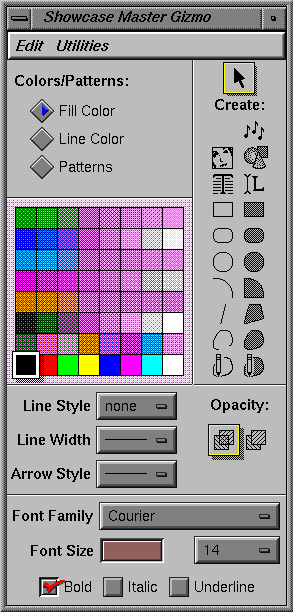
The Master gizmo comes up by default when you open IRIS Showcase. It contains the tools you need to draw, write, and insert images and 3D models. See Figure 11-6.
Use the left mouse button to select tools, or change colors, patterns, and line styles; double-click the left mouse button to use a tool repeatedly or to modify a color or pattern.
For more detailed information on the Master gizmo, see:
The Select tool (shown in Figure 11-7) lets you select objects in the drawing area, as well as tools in the gizmos and commands in the menus. You can also click on it to signal you have finished editing an object, or anytime you have difficulties and can't figure out how to finish what you are doing.
IRIS Showcase has two main text tools—the Block text tool and the Label text tool. See Figure 11-8.
Use Label text to type labels, captions, or other strings of text only a few lines long. See “Typing Labels”.
Use Block text when you want to prepare a memo or report, lay out several columns of text, or type more than several lines of text. See “Typing Blocks of Text”.
| Note: You can create a scrolling block of text by pressing the <Alt> key when you click on the Block text tool. Instead of a regular text box, you get a box with a scrolling bar along the left edge. See “Typing Scrolling Blocks of Text”. |
Some IRIS workstations have audio capabilities. To determine if your workstation supports audio, see “Does Your Workstation Support Audio?”.
You use the Audio tool (shown in Figure 11-9) with the Audio gizmo to make audio recordings and import audio files. Click the Audio tool and the File Browser appears. You can select an audio file to insert or you can open the Audio gizmo by clicking the Open Audio Gizmo button.
See “Adding Audio”
| Note: Adding audio to your document dramatically increases the file size. |
The 3D tool (shown in Figure 11-10) lets you insert 3D models. Click the tool with the left mouse button and the File Browser appears. Choose the 3D model you want to insert. See “Importing 3D Models” for detailed instructions and a list of the 3D file formats you can insert. You can also open the 3D gizmo by pressing the Open 3D Gizmo button on the File Browser.
In addition to importing 3D models, you can build your own models using tools on the 3D gizmo. See also Chapter 7, “Building 3D Models.”
| Note: Adding 3D models to your document dramatically increases the file size and slows down printing. |
You use the Image tool (shown in Figure 11-11) to insert image files. Click the Image tool and the File Browser appears. You can select an image file to insert.
You can also create your own images using the Image gizmo. See “Adding Images”.
| Note: Adding images to your document dramatically increases the file size and slows down printing. |
IRIS Showcase has 14 drawing tools—7 for filled Graphics objects and 7 for unfilled Graphics objects. Once you learn to use one, you can use them all. Click on the tool, move the cursor into the drawing area, and begin drawing. To draw most objects, press the mouse button and drag in any direction.
| Note: If you know you need to draw four circles, you can enter a permanent creation mode by double-clicking the left mouse button over the circle tool. When you finish drawing one circle, move the mouse and draw another one. To exit this mode, click the Select tool or any drawing tool. |
The choices for arrow style, line style, and line width appear in pop-up menus. Select an object; then place the cursor over the button next to “Arrow Style,” “Line Style,” or “Line Width.” Press the left mouse button to reveal a pop-up menu.
The style you choose becomes the active setting, with two exceptions. If you choose “none,” unfilled Graphics objects will still be drawn with an outline; otherwise, they would be invisible. Text objects and 3D models will be drawn without an outline.
See also:
All two-dimensional Graphics objects have an opacity setting. They're either opaque or transparent. You can use the opacity controls shown in Figure 11-12 to change this. The setting you select becomes active. Any new items you create will have this setting. Solid objects appear transparent only if you fill them with a pattern from the top row of the Pattern palette.
The bottom of the Master gizmo contains controls for changing the font family, size, and style.
The list of available fonts displays in a pop-up menu. This list may vary from one workstation to another, depending on the fonts that are installed. To select a font from the menu, place the cursor over the button next to “Font Family”; then press the left mouse button to reveal the menu. The name of the font you choose appears on the button. See Appendix F, “About Fonts,” to learn how to make IRIS Showcase recognize all of the fonts on your system.
If you create a document, and then view it on a workstation that doesn't have the specified font, IRIS Showcase substitues a different font. See the Status gizmo to find out what font is used as a substitute.
The list of available sizes also displays in a pop-up menu. Place the cursor over the button next to “Font Size”; then press the left mouse button to reveal the menu. The number you choose appears on the button. You can also type a font size in the editable field.
The three font styles—bold, italic, and underline—are shown at the bottom of the gizmo. Click the box next to the label to choose a style. A red checkmark indicates which styles are selected.
The Master gizmo contains one palette. You choose what you want to display in that palette—patterns or colors—by clicking the box next to the label “Fill Color,” “Line Color,” or “Patterns.”
The pattern palette displays 36 patterns. See Figure 11-13. Select a filled Graphics object or a 3D model, click on a pattern, and the object is filled with that pattern. The pattern that's selected is the active pattern; it is outlined. Any filled graphics objects you draw or 3D models you build will be filled with this pattern.
You can create your own pattern and add it to the palette.
Place the cursor over the pattern you want to replace; then double-click the left mouse button.
Choose any pattern but the solid one; you can't change it. And you might not want to change the patterns in the top row. They are useful for making solid objects appear transparent. The Pattern Editor shown in Figure 11-14 appears.

Note: You can also open the Pattern Editor by choosing “ Edit Patterns” from the Utilities menu on the Master gizmo.
To clear the pattern box, click the Clear all button.
All the squares change to white.
To change all the squares to black, click Set all.
To create the pattern, hold down the mouse button and click or drag in the grid. Click on white squares and they turn black; click on black squares and they turn white.
When you're finished, click the Apply button.
The new pattern appears as the current pattern in the palette.
| Note: IRIS Showcase allows only 36 patterns. Any objects that use the original pattern will switch to the new pattern when you press the Apply button. |
The Master gizmo contains one palette. You choose what you want to display in that palette—patterns or colors—by clicking the box next to the label “Fill Color,” “Line Color,” or “Patterns.”
Click the button next to the label “Fill Color” or “Line Color” to specify which color you want to change—the interior (fill) color of an object or the perimeter (outline) color of an object. The same colors display in each palette
.
The colors visible on the screen vary depending on the type of system you have. See “The Color Capabilities of Your Workstation” and “The “Full Color” Command”.
| Note: On 8-bitplane systems, colors that appear in the palette may not match those you set in the Color Editor. Objects drawn in this color print correctly, they just don't display correctly. Choose
“Full Color” from the View menu to get a better approximation of the colors as they will print. Your monitor can display colors that printers can't reproduce accurately. So some colors you see on the screen look different when you print them. If you've added new colors to the palette, and want them to appear in the palette each time you use the program, you can save them. See also “The “Set Preferences...” Command” |
You can add new colors to the palette.
Place the cursor over the color you want to replace; then double-click the left mouse button.
The Color Editor shown in Figure 11-16 appears.

Note: You can also open the Color Editor by choosing “ Edit Colors” from the Utilities menu on the Master gizmo.
The easiest way to select a new color is to hold down the left mouse button and drag the cursor around the color hex.
At the bottom of the editor you see a pair of colors. The one on the left, labeled “Adjust Color,” shows the color you select as you drag the cursor; the one on the right, labeled “Object Color,” is the color in the palette or the color of the selected object.
In between these colors, you see two arrows. One arrow points toward the original color; the other arrow points toward the new color.
To make the color lighter or darker, use the slider below the color hex. To choose a shade of gray, click the Gray button before using the slider. The sets the cursor to the center of the color hex, where the color is gray.
To apply the new color, click the arrow pointing to the right. The new color appears in the color palette in the Master gizmo. To reset the color, click the arrow pointing to the left.
| Note: To the left of the color wheel you see a set of buttons labeled H, S, and V, which stands for Hue, Saturation, and Value. Choose “RGB” from the Edit menu in the Color Editor and the labels change to R, G, and B. This stands for Red, Green, and Blue. You can choose a new color by changing these values. Set the values by clicking in the box next to the item you want to set. Then type in the number and press the <Enter> key. See “About RGB Color Settings” and “About HSV Color Settings”. |
You might want to duplicate the color of an object in a drawing, but you don't know its exact color values and the color isn't in the palette.
Place the cursor over the color you want to replace; then double-click the left mouse button. This opens the Color Editor.
Select the object whose color you want to copy and add to the palette.
The color is set to the selected object's color, as shown in the color box below the label “Object Color.”
In between the pair of colors, you see two arrows. Click the arrow pointing left.
The color is added to the palette.
To display RGB controls, choose “RGB” from the Edit menu in the Color Editor. The values for red, green, and blue correspond to how much the red, green, and blue color guns are turned on inside the monitor. 0.0 is completely off; 1.0 is completely on. If all three components are 0.0, all the guns are off, and the color is black. If all three components are 1.0, all the guns are on, and the color is white. If red is 1.0 and the other two are 0.0, the color will be the brightest red the monitor can display. If red and green are 1.0 and blue is 0.0, the color is yellow.
To display HSV controls, choose “HSV” from the Edit menu in the Color Editor. Hue corresponds to the pure colors of the rainbow. Red is arbitrarily chosen to have a hue of 0.0 (and 1.0). In the color wheel, hues are arranged circularly. As the hue increases the color changes to orange, yellow, green, cyan, blue, magenta, and back to red. Cyan has a value of 0.5.
Saturation refers to the amount of white mixed with a pure hue. It's arranged radially in the color wheel. If the saturation value is 1.0, the color is pure. If the saturation value is 0.0, the color is white. Here's an example: If the hue is 0.0, your base color is red. Decreasing the saturation value is comparable to adding white paint to a can of red paint. A saturation value of 0.5 means you've added half a can of white paint to your can of red paint. The result: pink.
Value refers to the lightness or darkness of a particular color. 0.0 is the darkest (black) and 1.0 is the brightest.
The Edit menu on the Master gizmo has four commands.
“ Make Jagged” and “ Make Smooth” let you make a smooth object jagged, and vice versa. “Drawing Equal-sided Polygons” provides an example of how you can use these commands.
Make Filled” and “ Make Unfilled” let you convert a filled graphic to an unfilled graphic, and vice versa. See also “Filling and Unfilling Objects”.
The Utilities menu on the Master gizmo has four commands.
“Edit Colors” and “Edit Patterns” open the Color and Pattern editors. You use these to create new colors and patterns.
“Lock Create Function” lets you use the selected drawing tool repeatedly. For example, suppose you want to draw four circles. Select the circle tool; then choose “Lock Create Function.” When you finish drawing one circle, move the mouse and draw another one. To exit this mode, click the Select tool or any drawing tool. As a shortcut, you can place the cursor over the drawing tool; then double-click the left mouse button. This command does not work for tools on the 3D gizmo.
The “Circle/Arrow Options” command opens the gizmo shown in Figure 11-17.
The top portion of the window lets you specify the number of arcs that make up a circle. The default setting is “6.” You can use this feature to create equal-sided polygons. For instance, drag the scroll bar to change the setting to “3;” then draw a circle. The circle looks like any other circle. Convert the circle to a jagged object using the “ Make Jagged” command on the Edit menu in the Master gizmo. See also “Drawing Equal-sided Polygons”

Note: You can set the circle edges only once. For instance, you cannot change the setting to “3” and create a triangle, then set it to “8” and turn the triangle into an octagon.
The lower portion of the window lets you change the shape of all arrows in the file. Use the scroll bar to the right of the arrow to change the height of the arrow; use the scroll bar below the arrow to change the length. Click the Apply Arrow Size button when you're finished. See also “Modifying Arrows”
IRIS Showcase provides four gizmos for working with 3D models—the main 3D gizmo, a Lighting gizmo, a Shadow gizmo, and a Texture gizmo. You access them from the 3D rollover menu on the Gizmos menu.
For more detailed information on the 3D gizmos, see:
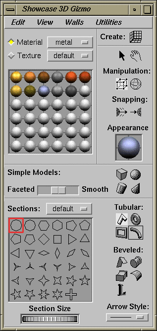
The main 3D gizmo is similar to the Master gizmo. It holds the basic tools you need to create and modify 3D models. See Figure 11-18.
To create 3D models, you first need to create a 3D container to hold them. You use the icon in the upper right corner of the gizmo to create such a container. See Figure 11-19.
Click the icon; then move the cursor onto the Showcase page. You see the outline of a box. This is the container. Click the left mouse button to place the outline or press the left mouse button and drag to resize the container. See “Creating a Container to Hold the 3D Models”
Figure 11-20 shows two icons. These icons let you switch between two modes—a working mode and a viewing mode. Click the arrow when you want to create, select, and manipulate models in the container; click the hand (the viewer tool) when you want to change your view of models in the container. See “Using the Viewer Tool”.
Figure 11-21 shows two icons. The icon you select determines what appears around selected models. When you want to rotate a model, click the sphere-shaped icon. This places a trackball around selected models. When you have finished rotating models and want to move or resize a model, click the cube-shaped icon. See also “Rotating 3D Models”.
The 3D gizmo has three sets of tools for building models. See Figure 11-22. Each set lets you create a different type of model. The shape of the tool indicates the type of model you can create.
The simple modeling tools let you create basic models—cubes, spheres, cones, and cylinders. The slider next to these tools lets you make a simple model smooth or jagged. To use the slider, select a simple model; then drag the slider.
The shape of a tubular model is determined by the tool you choose—line, circle, rectangle, or arc—and the shape of the cross section—circular, diamond-shaped, or star-shaped, for example. When you select one of these tools, a palette of cross sections displays in the 3D gizmo. See “Creating Tube-shaped Models”
The remaining set of tools let you create beveled models, including 3D text models. A bevel gives a model depth and determines the shape of its edges. When you select one of these tools, a palette of bevels displays in the 3D gizmo. See “Creating Beveled Models”
| Note: If you installed the inventor_eoe.demo.progs subsystem, you have access to revo and textomatic, two 3D demo programs in the /usr/demos/bin directory. You can copy models you create in the demo programs and paste them into IRIS Showcase. |
A palette appears in the lower portion of the gizmo. It displays cross sections or bevels. Figure 11-23 shows both palettes.
The cross section palette automatically appears when you select a tubular modeling tool or a model created with one of these tools. “Changing the Shape of a Cross Section” explains how you use the Cross-Section Editor to modify existing cross sections.
The bevel palette automatically appears when you select a beveled modeling tool or a model created with one of these tools. “Changing the Shape of a Bevel in the Palette” explains how you can use the Bevel Editor to modify existing bevels.
| Note: You can use the thumbwheel below the palette to make the cross section or bevel of a selected model larger or smaller. |
You can add arrows to one or both ends of models that you create using the tubular modeling tools. The lower right corner of the 3D gizmo contains a pop-up menu with available choices. To open the menu, place the cursor over the button below the label “Arrow Style”; then press the left mouse button. See “Adding Arrows to Tube-Shaped Models”.
A palette appears at the top of the 3D gizmo. It displays materials or textures.
To display the material palette, click the button next to the label “Materials.” IRIS Showcase provides several material palettes. The name of the material palette being displayed appears on the button. You can choose which of the material palettes you want to display. Place the cursor over the button to the right of the label “Materials”; then press the left mouse button to reveal a pop-up menu that lists available material palettes. See “Changing the Material of a 3D Model”
To display the texture palette, click the button next to the label “Textures.” See “Applying a Texture (Image) to the Surface of a 3D Model”
The Edit menu on the 3D gizmo has five commands:
“Edit Model” lets you edit text models and other models you create using the tubular or beveled modeling tools. When you edit a text model, you can add and delete characters; when you edit a beveled or tubular model, you change the shape of the model by adding and deleting points. See also “Editing 3D Models”
“Cap Model” and “Uncap Model” let you cap and uncap models that you create using the beveled or tubular modeling tools. An uncapped model is open-ended like a straw; a capped object is closed, like a cylinder. By default, all tubular models and most beveled models are capped. Beveled arcs and lines are the exception; they are uncapped by default.
“ Make Wireframe” and “ Make Solid” let you choose how to display the selected model, as a solid model or wireframe representation. If your workstation does not have the necessary graphics capabilities (a z-buffer), models will always display as wireframes.
You can view 3D models from all different angles—front, back, top, bottom, left, right, or any angle in between. The commands on the View menu let you switch from one view to another.
The “View All” command lets you quickly zoom out so that you can see all of the models in the container. It also centers the scene within the container. See also “Viewing All of the Models in a 3D Container”.
The “View Selection” command changes the view so the selected model is in the center of 3D container. See also “Viewing the Selected Model”.
The “Set Home” and “View Home” commands let you choose a custom view and easily return to it. See also “Setting a Home View”.
The six commands in the middle of the menu let you view models from six fixed positions—from the front, back, left, right, top, and bottom.
Three of the commands let you change the lens through which you view the models. “Wide Lens” makes the models appear farther away and smaller; “Normal Lens” preserves the normal size of the models; “Telephoto Lens” makes the models appear closer to you and larger. See “Changing the Lens Through Which You View the Models”.
The “Move Low Res” command is selected by default. It lets you move models more quickly by turning them into wireframe representations and turning off textures while you're doing interactive work.
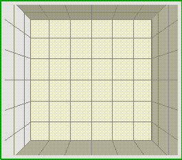
When you create and edit a 3D container, you see walls covered with grid lines as shown in Figure 11-24. Also see “About the Walls in the 3D Container”.
The walls and grid lines serve as a guide. They help you position 3D models within the container. The lines also indicate how a model will appear—in an upright position or slanted. Shadows appear on the walls when you select a model. You can use these to move and align models. The commands on the Walls menu let you temporarily turn off the walls and shadows.
“Show Walls” turns the walls off and on.
“Show Wall Shadows” turns the shadows off and on.
“Shrink to Fit” resizes the walls so that they fit the models in the container.
The Utilities menu has three commands that let you modify the material, cross section, and bevel palettes in the 3D gizmo. These commands are accessible when the associated palette is being displayed and an item in the palette is selected.
“Edit Material” opens the Material Palette Editor. This is equivalent to double-clicking on a sphere in the material palette.
“Edit Section” opens the Line Palette Editor so you can change the shape of a cross section. This is equivalent to double-clicking on a cross-section in the palette.
“Edit Bevel” opens the Line Palette Editor so you can change the shape of a bevel. This is equivalent to double-clicking on a bevel in the palette.
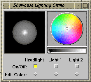
You can make a 3D scene look more realistic by lighting it using the Lighting gizmo, shown in Figure 11-25. To open this gizmo, choose “Lighting” from the 3D rollover menu on the Gizmos menu.
Each 3D container has up to three lights. The headlight is on by default. It's stationary. Think of it like the light on a miner's helmet; it always shines light directly onto the models. You can turn on the other two lights and position them in the container. When you turn on a light, an arrow appears on the sphere in the upper left corner of the gizmo. You move this arrow to position the light. Additionally, you can change the color of each light. See also “Lighting 3D Models”
When you select a model, it casts shadows onto the walls inside the 3D container. These shadows serve as guides. They help you move and position models, and they disappear when you stop editing the 3D container. See “About the Walls in the 3D Container”.
The Shadow gizmo lets you create shadows that you want as part of the 3D scene you create. See “Adding Shadows As a Finishing Touch” for step-by-step instructions.
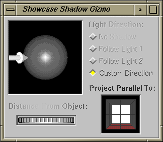
To open this gizmo, choose “Shadow” from the 3D rollover menu on the Gizmos menu. See Figure 11-26.
The upper right portion of the gizmo is labeled “Light Direction.” You use these four controls to turn the shadows off and on and choose the direction from which the light should come.
Select a model; then click “No Shadow” to temporarily turn off a shadow.
Select a model; then click “Follow Light 1” or “Follow Light 2” if you want the shadow to come from the direction of either of these lights. An arrow appears showing the postion of the light. These controls are accessible when the lights are turned on.
Click “Custom Direction” if you want to choose a different direction for the shadow. An arrow appears near the sphere. The arrow shows the direction from which the shadow will come. Place the cursor over the arrow; then press the left mouse button and drag the mouse. The arrow moves around the sphere. Release the mouse button when the arrow is positioned the way you want it.
The lower right portion of the gizmo shows the walls. You click on one of these walls to specify where you want the shadow to appear. The shadow is drawn parallel to the wall you select. By default, the floor is selected.
The thumbwheel lets you move the shadow. As you move the thumbwheel, the shadow moves toward or away from the shadow.
| Note: Once you position a shadow, it stays in that plane. For example, suppose you place the shadow of a model airplane on the ground, or runway. If you move the model airplane up, the shadow stays on the runway. It does not float above the runway. |
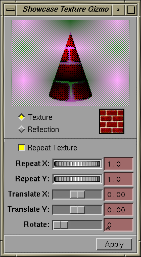
A texture is an image or pattern that you apply to the surface of a model. IRIS Showcase provides several palettes of sample textures. You can apply a texture to the surface of a model; then use the Texture gizmo to change the way that the texture displays on the model. Figure 11-27 shows the Texture gizmo.
The top portion of the Texture gizmo shows a copy of the selected model. (If you have selected several models, only the first model appears in the gizmo.) You can spin this model to view it from different angles.
Below the model, you see two buttons labeled “Texture” and “Reflection.” Click the diamond next to “Texture” if you want the texture to be wrapped around the model; click the diamond next to “Reflection” if you want the texture to be reflected onto the model. “About the Texture Gizmo” describes the differences.
If you choose “Texture,” the gizmo resembles Figure 11-27. If you choose “Reflection,” you only see the top portion of the gizmo. The remainder of this section describes the controls in the lower portion of the gizmo.
| “Repeat Texture” |
| |
| “Repeat X” and “Repeat Y”; “Scale X” and “Scale Y” |
| |
| “Translate X” and “Translate Y” |
| |
| “Rotate” | The scroll bar labeled “Rotate” lets you rotate the texture. |
If the selected model has a patterned applied to it, the Texture gizmo expands to show a color wheel. You can use this color wheel to change the color of the pattern without changing the color of the material. See “Using the Texture Gizmo to Change the Color in a Pattern”.
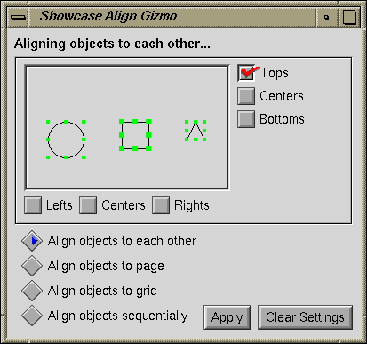
The Align gizmo contains the controls for lining up objects. You can line up objects with other objects, to the grid, to the page, or sequentially. See Figure 11-28.
Near the bottom of the gizmo, you see four lines of text: “Align objects to each other,” “Align objects to page,” “Align objects to grid,” and “Align objects sequentially.” Click the button next to one of these to specify the type of alignment you want.
“Align objects to each other” lets you select several objects and align them to each other. See “Lining Up Several Objects” for step-by-step instructions.
“Align objects to page” lets you position objects on the page. For example, you can use this function to position an object two inches from the left edge of the page and three inches from the top of the page. See “Placing Objects in an Exact Location on the Page” for step-by-step instructions.
“Align objects to grid” lets you line up the edges and centers of objects with a grid. To use this, you must choose a grid setting from the View menu. Select the objects you want to align and specify which part of the objects you want to align with the grid. See“Aligning Objects to a Grid” for step-by-step instructions.
“Align objects sequentially” lets you create uniform spacing between objects. You specify the size of the gap you want, and whether you want it from “Top to Bottom” or “Left to Right.” See “Aligning Objects Sequentially” for step-by-step instructions.
The Audio gizmo lets you make a recording and add it to your IRIS Showcase document, as well as import existing audio files. Figure 11-29 shows the Audio gizmo. “Adding Audio” provides step-by-step instructions for adding audio to your IRIS Showcase document.
The lower left corner of the Audio gizmo contains three buttons: Record, Stop, and Play. You use these when you make a recording.
Click Record to begin recording.
Click Stop to signal you are finished recording.
Click Play to play the recording or to play the selected audio object in the drawing window.
The area in the middle of the gizmo displays the audio waveforms. The waveforms appear when you record or when you edit an audio object in your IRIS Showcase document. The waveform for the right channel is red; the waveform for the left channel is blue.
The two buttons in the lower right corner, the Clear Audio button and Add Audio Clip button, are grayed out; they become available after you've recorded something. Also, if you edit an audio object the Add Audio Clip button changes to Replace Audio Clip. You can replace that audio object with a new recording.
| Note: When you click the Add Audio Clip button, IRIS Showcase creates a temporary file in a directory in /usr/tmp. If you don't have enough disk space, IRIS Showcase displays a message telling you that it can't create the audio file. To change to a directory other than /usr/tmp, use the “ Set preferences...” command. |
The Utilities menu contains two commands: “Audio Control Panel” and “ Insert from file...”
Choose “Audio Control Panel” to invoke the Audio Control Panel. This panel controls the sample rate at which you record and play audio, the volume, and the input source. By default, IRIS Showcase sets the input source to “Mic” and the sample rate for recording to 16K. The sample rate for playing is set to match the rate at which the audio was recorded. See the IRIS Utilities Guide for additional information on the Audio Control Panel.
Choose “ Insert from file...” to import an audio file stored in the AIFF format. When you choose this command, the File Browser appears. If you have installed the PROSONUS sound library, IRIS Showcase displays the contents of /usr/lib/sounds/prosonus. See “Finding Sample Audio Files” for information on the sample sounds that are available.
The HyperScript gizmo lets you create dynamic on-screen presentations and help files. Each hyperscript has two components:
A list of the actions that will happen when the hyperscript is run. For example, a hyperscript might contain two actions—turn to a specific page; then play a specified audio clip.
The event that causes the hyperscript to run. A hyperscript can run when a user double-clicks an object, turns to or from a page, or opens or closes a file.
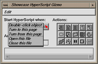
Figure 11-30 shows the gizmo. See “Using HyperScripts” for detailed instructions on creating hyperscripts.
This gizmo has five main components: a pop-up menu, a palette of buttons from which you construct the hyperscript, an area that gives a description of each button, a preview area that shows an icon for each action in the hyperscript, and an Edit menu.
Figure 11-31 shows the pop-up menu. To open it, you place the cursor over the button below the label “Start HyperScript when”; then press the left mouse button.
The items on the menu let you specify what action should cause the hyperscript to run.
You use the buttons in the palette to build a hyperscript. Place the cursor over a button and a description of the action it will cause appears under the label “Action Description.” Click the button to add it to the script and an icon appears in the scrolling area at the bottom of the gizmo.
The Edit menu in the HyperScript gizmo contains commands you use to delete actions from a hyperscript, delete the entire hyperscript, and check and run hyperscripts.
The Image gizmo lets you take snapshots of sections of your screen and bring them into your document as images. See Figure 11-32. “Adding Images” and “Creating Images” provide step-by-step instructions; this section explains the buttons and menu choices on the Image gizmo.
The Image gizmo provides five buttons:
| Sweep area | Click this button when you want to create a snapshot; then click in the box next to “Grab Selection focus” or press the <Shift> key. Move the cursor to the area of the screen that you want to capture. the press the mouse button and sweep out a box around the area you want to capture. | |
| Grab Image | Click this button when you are ready to capture the area of the screen you have selected. Move the cursor back into the drawing area. When the image is ready a red rectangle appears. | |
| Reset | Click this button if you want to begin again. | |
| Grab Selection Focus |
| |
| Vanish While Saving |
|
The magnify box in the middle of the gizmo changes after you click the Sweep area button. It shows the section of the screen your cursor is over. A small blue box appears there, and the cursor changes into a small camera. Use the crosshair in the camera and the small blue box to position the cursor precisely.
The Utilities menu has three commands: “Original Aspect Ratio,” “Original Size,” and “ Insert From File.” The first two let you restore the original size and aspect ratio of an image. “ Insert From File” brings up the File Browser so you can import an existing image file.
| Note: When you click the Grab Image button, IRIS Showcase creates a temporary file in a directory in /usr/tmp. If you don't have enough disk space, IRIS Showcase displays a message telling you that it can't create the image. To change to a directory other than /usr/tmp, use the “ Set preferences...” command. To reduce the amount of disk space required, you can shrink the image in your document; then take a screen snapshot of the image at its new size and delete the original. This reduces the amount of information IRIS Showcase needs to store in the file. |
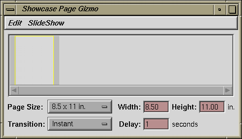
The Page gizmo contains controls for changing page sizes, rearranging and deleting pages, setting page transition styles, and creating self-running slide shows. See Figure 11-33.
The Page Preview area is in the middle of the gizmo. A snapshot of each page in your document appears in this area. If you are viewing page-note pages or template pages, a snapshot of these pages appears in the preview area.
A scroll bar appears if the area is too small to display all the snapshots. You can select pages by clicking on the snapshots. To select multiple pages, press the <Shift> key while clicking. A yellow outline surrounds selected pages. The selected pages are affected by commands on the Edit menu and page size, transition, and delay settings. You can also move these snapshots to rearrange pages in the file.
The page size settings are in a pop-up menu. To open the menu, place the cursor over the button next to the label “Page Size”; then press the left mouse button. To specify a custom size, choose “custom” from the menu, type the page size in the fields provided, then press the <Enter> key. See “Changing Page Sizes” for step-by-step instructions on changing the page size.
The transition styles are also in a pop-up menu. The transition style determines the way the selected page is displayed when you turn to it—from left to right, from top to bottom, or in strips resembling vertical or horizontal blinds, for example. By default, all slides are set to “Instant.”
To open the pop-up menu, place the cursor over the button next to the label “Transition”; then press the left mouse button. See “Setting Page Transitions” for step-by-step instructions.
The Delay field works in conjunction with commands on the SlideShow menu. It lets you specify how many seconds you want the selected page to display in a self-running slide show. Type a number in the field; then press the <Enter> key. “Creating a Self-running Slide Show” provides step-by-step instructions for creating a slide show.
The Edit menu has two commands: “Select All Pages” and “Delete Selected Page(s).” When you choose “Select All Pages,” a yellow outline surrounds each snapshot in the Page Preview area. When you choose “Delete Selected Page(s),” all of the selected pages are removed from the document.
The SlideShow menu has four commands. The first command on the menu, “Start Slide Show,” lets you preview a slide show you have created. “Run Once” and “Run Continuously” let you choose how many times you want the slide show to run—once or repeatedly. The last command, “Set Page Range...” opens a dialog box that lets you choose the range of pages in the document that you want to include in the show.
IRIS Showcase prints instructions, information, and error messages into the Status gizmo, which appears by default when you run IRIS Showcase. See Figure 11-34. You can resize the gizmo if the default size is inconvenient, and you can place the gizmo elsewhere on the screen. Once you've done so, use the “ Set Preferences...” command to save the size and location. See also “The “Set Preferences...” Command”
You can also stow or close the Status gizmo. Messages continue to get sent to the Status gizmo. If an error message or warning is sent to the Status gizmo, IRIS Showcase automatically re-opens the gizmo.
Templates are one-page files that contain all of the objects you want to place in the background and have appear from page to page—headers, footers, logos, and page numbers, for example. Templates also contain placeholders for text.
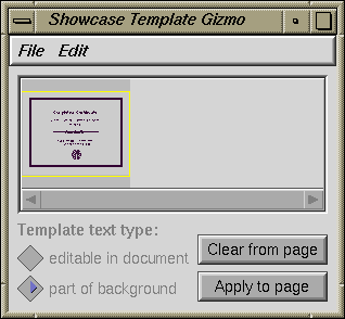
You use the Template gizmo to create and import templates. See Figure 11-35.
The center area of the gizmo displays a snapshot of each template you're using in the file. The area is blank if you're not using any templates yet. The snapshot that is highlighted with a yellow border is selected. To edit a template, you can place the cursor over the snapshot; then double-click the left mouse button.
The controls in the lower left corner of the gizmo determine the behavior of Text objects.
Click the box next to “part of background” if you want the text to be identical on every page that uses the template. Your company name and address should be the same on every memo, for example. If you want to modify it, you have to edit the template.
Click the box next to “editable in document” if you want to define a placeholder for the text, but change and add to the words while editing your document. The body of the letter is a good example. The text appears in the same place, but the words are different. When you choose “editable in document” the Text object is copied onto every page that uses that template.
The buttons in the lower right corner let you apply a template to a page or clear a template from a page.
The File menu in the Template gizmo contains three commands: “Import,” “New,” and “Save.”
Choose “Import” and the File Browser appears so you can select a template to import.
Choose “New” and a snapshot of a blank template appears in the center of the Template gizmo. To add objects to the new template, you must edit it.
Once you bring a template into the Template gizmo, it becomes a part of the IRIS Showcase document. When you save the document, the template files are automatically saved with it. You can also save the template as a separate template file somewhere on your workstation's disk. To do so, you use the “Save” command.
The Edit menu on the Template gizmo contains three commands: “Edit,” “Delete,” and “Delete All. ”
Select a snapshot; then choose “Edit” and the main drawing window changes to display only the objects on the template. Now you can add new objects and delete or edit existing objects on the template.
If you decide not to use a template, you can delete it from the Template gizmo. Select a snapshot; then choose “Delete.” To delete all of the templates in that file, choose “ Delete All.”
“Working with Templates” provides step-by-step instructions for importing, creating, and modifying templates. Refer to this section for more information.
IRIS Showcase provides three gizmos for working with text—the main Text gizmo, the Keyboard gizmo, and the Search/Spell gizmo.
For detailed information on the text gizmos, see:
The main Text gizmo contains commands to help you edit text and layout pages. It's divided into three sections. The top section affects entire Text objects; the middle section affects paragraphs of text; and the bottom section affects characters. See Figure 11-36.
The Create button at the top of the Text gizmo lets you connect two block Text objects. When Text objects are connected, text that doesn't fit in the first object flows into the second object. The Break button lets you break the connection between the objects.
To connect two Text objects, select a block Text object; then click the Create button. That area of the Text gizmo changes. It displays instructions. Select another block Text object—the one into which you want to flow the text—then click the Finish or Continue button. See “Flowing Text from One Text Block to Another” for detailed instructions.
You can break the connection by selecting the Text object then clicking the Break button.
The Split block icons shown in Figure 11-37 split a Text object into vertical and horizontal columns. Select a Text object created using the Block text tool, and click on one of these. The object splits in half, forming two separate objects that are linked. You can move and resize each object separately.
If you enlarge the left or upper column, text from the right or lower column shifts and fills up the added space. The reverse happens when you shrink the first column. See “Creating Multiple Text Columns” for step-by-step instructions.
The text conversion icons let you convert Text objects from one type to another—from Scrolling to Block, from Block to Label, and so on. (See “Typing Text” for an explanation of the different types.) To convert text, select the Text object you want to change; then click the appropriate icon. See Figure 11-38.
| Note: A 3-inch long scrolling Text object can hold much more than 3 inches of text. If you convert this to Block text, however, the box will be able to hold only the first 3 inches of text. To regain the remaining text, either enlarge the text box or create a new text box and flow the text into it. If you convert Block or Scrolling text to Label text, you may get surprising results. Label text doesn't make automatic line breaks, so it will break the line only when you force a carriage return. |
The Text gizmo has controls that let you adjust the amount of space before and after a paragraph as well as between lines within a paragraph. This spacing is measured in points, as are fonts. (A point is 1/72 of an inch.)
To set the spacing, place the cursor in the field next to the label “Before,” “Within,” or “After”; then type the number for paragraph spacing or use the arrows at the bottom of that section of the gizmo. The space is measured in points. A positive number adds space; a negative number reduces space. (Stick with a spacing of one or two if you're typing large blocks of text. This spacing makes for the easiest reading.) If you typed in a number, press <Enter> and the text adjusts to the new spacing. See also “Adjusting the Space Before and After Paragraphs” and “Adjusting the Space Between Lines in a Paragraph”
You have four choices for justification:
Left lines up text with the left margin; the right side is
ragged.Right lines up text with the right margin; the left side is ragged.
Justified lines up text with both margins.
Centered centers text on a line.
To change justification, click on the appropriate icon. The text in all selected paragraphs changes. See “Centering and Justifying Your Text”
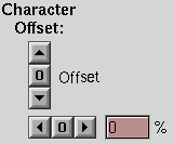
The character offset arrows in the Text gizmo let you create subscripts and superscripts and adjust the amount of space between selected characters. See Figure 11-39. Select the text you want to change; then click the arrows. The text changes. To restore the text to its original position, select the offset text; then click the zero in between the arrows.
See also “Using Subscripts and Superscripts” and “Adjusting the Space Between Characters”
The lower right corner of the Text gizmo contains a column of three buttons. The Time, Date, and # buttons automatically insert the time, date, or page number in a document. Just click the button while typing or editing text and the date, time, or page number is inserted in your document. The time and date gets updated each time you open the file.
| Note: IRIS Showcase inserts the time at which you started running the program, not the time at which you click the button. |
The Edit menu has one command—” Create Dangling Flow.” Select a block Text object, and then choose this command, and you create an open-ended text block. See “Flowing Text from Page to Page”
The Utilities menu has four commands:
“Find” lets you search for a word. If you haven't already used the Search/Spell gizmo to specify a word to search for, the “Find” command opens the Search/Spell gizmo.
“Replace” works with the “Find” command. It lets you replace the selected word with text you have specified in the Search/Spell gizmo.
“Jump to Line” lets you move to a particular line in a Text object you're editing. Choose this command and a dialog box appears. Type a line number into the dialog box, click the Accept button, and that line is highlighted.
“Make 2D Graphic” copies a Text object and turns each letter in it into a 2D Graphics object. Choose this command if you want to apply a pattern to the text, shade it, or scale each letter separately. Select the Text object; then choose this command. Move the cursor into the drawing window; then click the left mouse button to place the copy. At this point, each letter is a separate Graphics object. You can scale each letter separately and apply patterns. See “Turning Text into a 2D Graphics Object”
The Keyboard gizmo shows the sets of characters available. Pop it up while editing a Text object and you see the standard letters, numbers, and symbols for the font currently selected. Press the <Alt> and <Ctrl>, or <Shift>, <Alt>, and <Ctrl> keys simultaneously, and you see different sets of characters.
You can type characters from the gizmo by clicking the left mouse button over keys, or you can type from the keyboard.
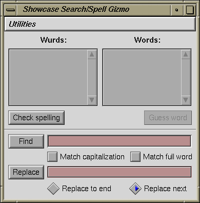
The Search/Spell gizmo lets you check your spelling. See Figure 11-40.
The Search/Spell gizmo contains controls for checking your spelling and searching for and replacing words.
You can check your spelling Text object by Text object. If you have several unrelated Text objects, you need to spell check each separately. If an object is connected to another, the Search/Spell gizmo scans the entire chain, looking for words it doesn't recognize. To check the spelling in a Text object, you should be editing it.
This spell checker is a front-end to the IRIX spell utility. When it guesses a word, it usually finds the correctly spelled word, but it may also display some incorrectly spelled words.
Because the spell checker in IRIS Showcase is a front-end to the IRIX spell utility, you must have spell installed. Any enhancements you make to spell will be available through the checker in IRIS Showcase. See the spell(1) man page for details.
The controls for Find and Replace are in the lower portion of the Search/Spell gizmo. Type the word you want to search for in the field next to the Find button. If you want to replace it with another word, type that in the field next to the Replace button.
See “Searching for Text” and “Replacing Text” for step-by-step instructions and an explanation of the different options for searching and replacing text.
