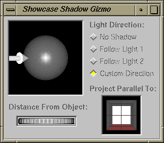
Chapters 5 and 6 explain how you create and work with several types of two-dimensional objects—blocks of text, rectangles, and lines, for example. This chapter explains how you create and work with 3D models.
The tools on the Master gizmo let you draw two-dimensional pictures; the tools on the 3D gizmo let you build three-dimensional models. This section describes the fundamental differences between drawing pictures and building models.
Take for instance the difference between drawing an airplane and building a model of that airplane. When you draw an airplane, you decide where to place it on the page, how long or tall to make each line, how large the whole drawing should be, and whether to fill in the drawing or leave it as an outline.
When you build a model of a plane, you decide what the relative dimensions should be for each piece of the plane—the wings, the wheels, the nose, and the tail, for example. You decide how to attach, or glue together, the pieces to build a realistic looking model, and you decide where to place the model when it's finished. For example, suppose you have a collection of models hanging from the ceiling. You decide where to hang this model—how far from the walls and from the ceiling and how far from other models in the room.
This list highlights a few of the differences between drawing pictures (2D) and building models (3D):
Two-dimensional pictures are flat. They have width and height, which you can see, measure, and change. Three dimensional models have width, height, and depth.
When you create two-dimensional pictures, you position them on the page. When you create three-dimensional models, you position them inside of a 3D container.
For example, to create a two-dimensional picture, you select a tool from the Master gizmo, move the cursor into the drawing area, then draw the picture directly on the page. The picture on the page is similar to a magnet on a refrigerator. You can move the picture up and down and from side to side, but it is stuck to the surface.
To create a three-dimensional model, you must first designate a portion of the page as 3D space. You do this by creating a 3D container to hold the models. The models have height, width, and depth, and you can move them in three dimensions—left and right, up and down, and toward and away from you. See “Creating a Container to Hold the 3D Models” for step-by-step instructions on creating the 3D container.
Because a picture is flat, you can view it in only one way—from the front. You can view models from all different angles—front, back, top, bottom, left, right, or any angle in between.
The appearance of a two-dimensional picture is determined by its color, its pattern, and the width of its lines. The appearance of a three-dimensional model is determined by its material, its texture, its lighting, and the shadows it casts.
You can make pictures and models smaller or larger by resizing them. Additionally, you can make 3D models appear larger or smaller by changing their position in the 3D container. The farther away the model, the smaller it appears. The closer the model, the larger it appears. This is called perspective.
3D models display as wireframes if your IRIS workstation doesn't have the necessary graphics capabilities (a z-buffer) to display them in a solid form. You can still create and modify 3D models even if they display as wireframes. The models will print correctly and will display correctly if you open the file on a machine with a z-buffer.
In this section, you learn basic techniques for manipulating and creating 3D models. You begin working with models in a sample file; you advance to build your own sample model. You do not learn how to use all of the 3D capabilities. The remainder of the chapter provides step-by-step instructions for using all of the 3D capabilities.
Opening a File for the Sample Session
You begin the session by opening a sample file.
Choose “ Open” from the File menu.
The File Browser appears.
Choose 3DSampleFile from the /usr/lib/Showcase directory.
The File Browser disappears. 3DSampleFile opens.
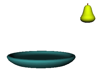
In the center of the page, you see a bowl and a pear, as shown in Figureá7-1.
| Note: These models should appear solid. They display as wireframes if your IRIS workstation doesn't have the necessary graphics capabilities (a z-buffer) to display models in a solid form. You can continue with the sample session. |
Selecting and Editing a 3D Container
To start working with the model:
Place the cursor over one of the models; then click the left mouse button.
Small green squares appear, forming a box around the models. These squares show the outline of the 3D container that holds the models. You have just selected this container.
The 3D container is similar to a block of text. A block of text is an object that contains words; a 3D container is an object that contains 3D models. (A collection of models is called a scene.)
Choose “ Edit Object” from the Edit menu.
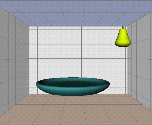
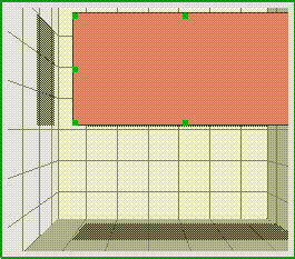
A light-green box surrounds the container. Inside the container, you see walls with grid marks. The floor is tinted pink; the ceiling is tinted blue. See Figureá7-2. These walls help you create and position the models in the container. See “About the Walls in the 3D Container.”
The light-green box and the walls indicate that you are editing the 3D container. Now you can build new models and manipulate and modify existing models.
Viewing the Bowl and Pear From Different Angles
You can view 3D models from different angles—front, back, top, bottom, left, right, or any angle in between. To change your view of the models, you rotate the scene inside of the 3D container.
Open the 3D gizmo by choosing “ 3D” from the Gizmos menu.
The 3D gizmo appears.
Choose “ View Bottom” from the View menu on the 3D gizmo.
The view changes. You see the underside of the bowl and pear.
You can also change the view by spinning the scene.
Place the cursor over one of the walls, making sure the cursor isn't over either of the models.
Press the left mouse button. A black line and a circle appear. The circle shows which way you'll spin the scene; the black line represents the axis about which you'll rotate the scene.
Continue pressing the mouse button and drag the mouse. The scene spins inside of the container.
Release the mouse button.
Return to the original view by choosing “ View Front” from the View menu on the 3D gizmo.
For more instructions on changing your view of the models, see “Changing Your View of 3D Models.”
You can move 3D models up and down, left and right, and closer toward or farther away from you. This section presents one technique you can use to move models around in the container. See also “Moving 3D Models.”
Place the cursor over the model of the pear; then click the left mouse button once to select it.
A bounding box appears around the selected model, and the selected model casts shadows onto the walls.
Press the <Shift> key while clicking on the model of the bowl.
Now both models are selected. You can see the shadows each model casts; you can compare the shadows to see how they're positioned.
Press the <Shift> key again; then click the bowl to deselect it.
At this point, the pear should be the only thing selected.
Place the cursor over the shadow the pear casts onto the floor, or bottom wall.
Press the left mouse button and slowly drag the cursor left and right, and up and down. The model moves parallel to the wall upon which the shadow is cast. For example:
When you move the cursor left and right, the model moves to the left and right.
When you move the cursor up and down, the model moves closer toward or farther away from you.
The walls automatically move to make space for the models. For example, if you raise the pear so that it touches the top wall (ceiling), the ceiling moves and additional grid lines appear on the wall.
Creating a 3D Container to Hold the Sample Models You Will Create
You've practiced manipulating 3D models; now you're going to create a few sample models. To get started, you open a new file and create a 3D container.
Choose “New” from the File menu.
A notifier appears asking whether you want to save or discard your changes to the file 3DSampleFile. Click the Discard button.
Once you have a new file, you need to make a 3D container to hold the models you're going to create.
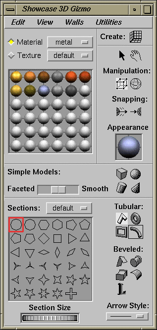
Click the icon in the upper right corner of the 3D gizmo. See Figureá7-3.
Move the cursor into the drawing window; then press the left mouse button and drag.
Release the mouse button when the container is almost as large as the page.
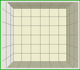
When you release the mouse button, you see walls with grid marks and a thin green outline that surrounds the container. See Figureá7-4.
The green outline means that you are editing the 3D container. The walls help you create and position the models in this container. See “About the Walls in the 3D Container.”
In this section, you learn how to use one of the simple modeling tools—the cylinder tool—to build a table top and four legs for the table.
Place the cursor over the cylinder tool in the 3D gizmo; then click the left mouse button.
The cylinder tool is one of the four simple modeling tools in the 3D gizmo. See Figureá7-5.
Place the cursor inside of the 3D container you created.
Hold down the left mouse button and drag down and to the right. Drag down only a small amount to keep the table top thin.
A wireframe representation of the model appears.
Release the mouse button when the wireframe resembles a table top. The table top appears. See Figureá7-6.
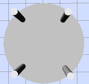
Now you can make the four legs for the table. To make it easier, you're going to change views so that you're looking at the bottom of the table.
Choose “View Bottom” from the View menu on the 3D gizmo.
Now you're looking at the underside of the table top.
Select the cylinder tool in the 3D gizmo.
Place the cursor near the upper left edge of the table; then press the middle mouse button and drag.
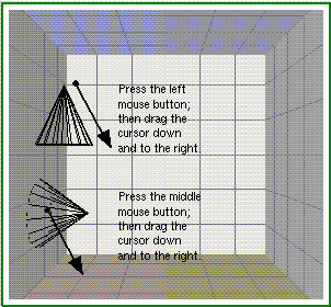
To make the table top, you used the left mouse button. Here, you use the middle mouse button. It lets you create models perpendicular to the surface on which you place the cursor. See Figureá7-7.
Make sure that the leg is still selected; then choose “ Copy” from the Edit menu on the main Showcase window.
Choose “ Paste” from the Edit menu on the main Showcase window; an outline of the leg appears when you move the cursor back into the 3D container.
Move the outline around until it's positioned near the upper right edge of the table.
Repeat steps 5 and 6 so your table has four legs. See Figureá7-8.
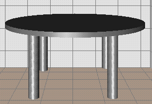
You've finished making the table. Before moving on, you should change views and group the table top and legs.
Choose “View Front” from the View menu on the 3D gizmo.
The view changes. See Figureá7-9.
Choose “ Select All” from the Edit menu on the main Showcase window.
The table top and the four legs are selected.
Choose “ Group” from the Edit menu on the main Showcase window.
The table top and four legs are grouped together as one model.
Importing a Model to Place on the Table
This section describes how you import a pear to place on the table.
Make sure that you are still editing the 3D container. A light-green box surrounds the container when you're editing it and, inside the container, you see the walls with grid lines.
If you're not editing the 3D container, place the cursor over the table; then double-click the left mouse button.
Choose “3D Model...” from the Insert rollover menu on the File menu.
The File Browser appears. By default, it displays the contents of the directory /usr/share/data/models.
Choose Pear.iv from the File Browser.
Move the cursor into the drawing window. An outline of the pear appears inside of the container.
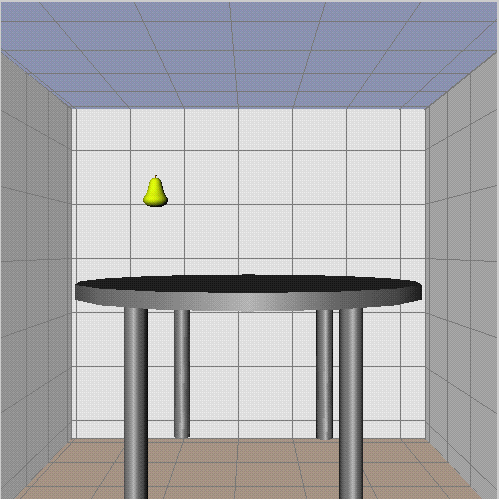
Position the wireframe so it is floating above the table top; then click the left mouse button to place the pear. See Figureá7-10.
The pear is probably too large for the table. To resize it:
Make sure the pear is still selected. A bounding box appears around the model when it's selected.
Place the cursor over one of the green corner squares on the bounding box.
Press the <Shift> key; then press the left mouse button and drag the cursor to resize the model.
The corner squares and the <Shift> key let you adjust the height, width, and depth of the model.
Release the mouse button when you're satisfied with the size of the pear.
Placing the Pear on the Table
The snapping tools make it easy for you to set the pear on top of the table.
Make sure that you can see the bottom of the pear. If you can't, move the pear up until the bottom is visible.
The snapping tool consists of two icons in the 3D gizmo. The left icon is the “snap from” icon; the right icon is the “snap to” icon. Place the cursor over the left icon; then click the left mouse button. See Figureá7-11.
Place the cursor over the bottom of the pear; then press the left mouse button. A red arrow appears. It shows what portion of the pear you want to attach to another model.
Now you can select the model that you want to attach it to. To make it easy, choose “View Top” from the View menu on the 3D gizmo.
The view changes. You see the top of the table.
Place the cursor over the table top then click the left mouse button. The pear snaps into place.
Leave the view the way it is so that you're looking down on the table top.
Making a Cup to Place on the Table
The model of a cup has two pieces: the main part of the cup and the handle. You use the cylinder tool to make the main part of the cup and one of the tubular modeling tools to make the handle.
| Note: This example gives you practice using the modeling tools. However, the cup you create is not realistic. The cylinder tool creates a solid cylinder. As you become more experienced using the modeling tools, you'll discover how to use the beveled modeling tools to create a more realistic model of a cup. |
Place the cursor over the cylinder tool in the 3D gizmo; then click the left mouse button.
Place the cursor anywhere on the table top; then press the middle mouse button and drag.
You use the middle mouse button because it creates the cylinder perpendicular to the table top, that is, the bottom of the cylinder sits on the table top.
Choose “ View Front” from the View menu on the 3D gizmo to return to the front view.

Note: If the cylinder is too large or small, resize it using the same technique you used to resize the pear.
Making the Handle
Next, you make the handle. To make this easier, you will zoom in to see the cup more closely.
Press the <Alt> key and the middle mouse button; then drag the mouse down.
The models come closer.
Release the mouse button and <Alt> key when the cup is large enough for you to work with easily.
Select the tubular arc tool in the 3D gizmo. This tool resembles a curved piece of macaroni. See Figureá7-12.
Creating an arc takes two steps. First, you make a circle; then you choose which portion of the circle you want for the arc.
Place the cursor below the cup, and to the right.
Press the left mouse button and drag the mouse.
The outline of a circle appears. A portion of this circle will become the handle.
Release the mouse button when the circle is sized appropriately. A straight line appears inside of the circle.
Now you need to sweep out the section of the circle that you want for the handle.
Imagine that the circle is a clock. Place the cursor where the number 11 would be on the clock; then press the left mouse button and drag to the right.
Continue holding down the left mouse button and drag. An outline of the arc you're creating appears.
Release the mouse button when the outline of the arc resembles a handle and the cursor is approximately where the number 6 is on a clock.
Attaching the Handle
You use the snapping tools to attach the handle to the main part of the cup. You begin by changing your view of the scene so you can see the edge of the handle that you want to attach.
Choose “View Left” from the View menu on the 3D gizmo.
The view changes. You see the ends of the handle.
Click the “snap from” icon. It's the left icon in the pair of snapping icons.
Place the cursor over the top end of the handle; then click the left mouse button.
A red arrow appears. It shows what portion of the handle you want to attach to another model.
Choose “View Front” to return to the front view.
Rotate the scene slightly so you're viewing the edge of the cup.
Place the cursor over the floor; then press the left mouse button. A black line and a circle appear.
Continue pressing the mouse button and drag the mouse. The scene spins inside of the container.
Release the mouse button when you can see the side of the cup to which you want to attach the handle.
Place the cursor over the cup; then click the “snap to” icon. The handle snaps onto the cup.
If the handle is too large or isn't centered, you might need to move the handle or resize it slightly.
Return to the original view by choosing “ View Front” from the View menu on the 3D gizmo.
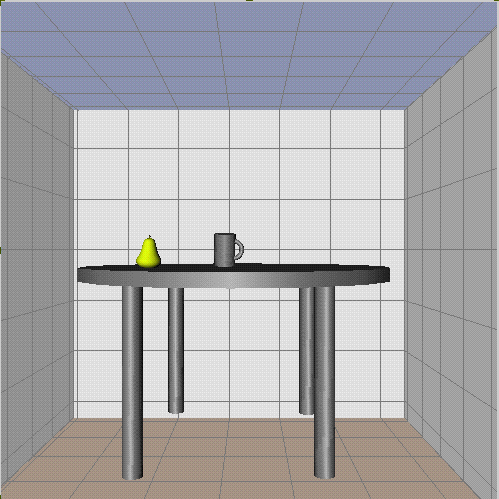
The cup is finished and you have completed the sample session. The scene you created should resemble the one shown in Figureá7-13.
You can import a 3D model using one of two methods. You can click the 3D tool on the Master gizmo or you can use the “ Insert” command on the File menu.
You can import two types of models into an IRIS Showcase file.
models saved as IRIS Inventor™ 3D models
models saved in AutoCAD«'s DXF format
For detailed information on the IRIS Inventor file format, see the IRIS Inventor Programming Guide. For detailed information on the DXF format, see the AUTOCAD Reference Manual, published by Autodesk, Inc.
Click once on the 3D tool in the Master gizmo. See Figureá7-14.
The File Browser appears. IRIS Showcase displays the contents of /usr/share/data/models by default. If you installed the inventor_eoe.data subsystem, the directory contains many sample model files; otherwise, it contains several model files.

Note: You can designate a different directory in which you want IRIS Showcase to look for model files. See also “The “Set Preferences...” Command.” Select the file you want to open.
The File Browser disappears. A dialog box may appear if you're importing a large DXF file that will translate slowly.
Move the cursor into the drawing area.
The outline of a red rectangle appears in the drawing area. Click the left mouse button to bring the model into a 3D container that is the size of the rectangle, or press the left mouse button and drag in any direction to enlarge or reduce the rectangle. Release the mouse button when the container is the size you want. The model appears.
| Note: Models display as wireframes if your IRIS workstation doesn't have the necessary graphics capabilities (a z-buffer) to display models in a solid form. |
You can import 3D models by choosing “3D model...” from the Insert rollover menu on the File menu. When the File Browser appears, choose the model that you want to import; then move the cursor into the drawing area. One of two things happens.
If you are editing a 3D container, the model is inserted into that container. If the model is too large or small, you can make it appear larger or smaller by zooming. See “Zooming and Panning Using the Walls.”
If you are not editing a 3D container, the outline of a rectangle appears in the drawing area. Click the left mouse button to bring the model into a 3D container that is the size of the rectangle, or press the left mouse button and drag in any direction to enlarge or reduce the rectangle. Release the mouse button when the container is the size you want.
| Note: Models display as wireframes if your IRIS workstation doesn't have the necessary graphics capabilities (a z-buffer) to display models in a solid form. |
You can save selected models as Inventor files. This makes it easy to use these models in other applications that recognize the Inventor file format. To do so, select the models; then choose “ ...As 3D (Inventor)” from the Save As rollover menu on the main File menu.
You have two options for selecting models:
Select a 3D container if you want to save the entire scene.
Edit a 3D container; then select models inside of the container if you want to save only those models. If you don't select any models inside the container you're editing, you save the entire scene.
| Note: If you are familiar with the IRIS Inventor file format and want to view the contents of the file, use the program ivcat, which is part of the inventor_eoe subsystem. |
To build 3D models, you must first create a 3D container to hold the models. The 3D container is like other objects on the IRIS Showcase page. You select it, move it, resize it, and align it just as you do an image or circle on the page. See Chapterá3, “Working with Objects,” for further instructions on manipulating the 3D container.
| Note: A block of text is an object that contains letters and words. Similarly, a 3D container is an object that contains models. |
For information on using the container, see:
To create a new 3D container:
Open the 3D gizmo by choosing “ 3D” from the Gizmos menu.
The 3D gizmo appears.
Click the icon in the upper right corner of the 3D gizmo. See Figureá7-15.
Move the cursor into the drawing area. You see the outline of a box.
Click the left mouse button to create a container of that size, or to sweep out a 3D container:
Press the left mouse button and drag in any direction. The red outline indicates the size of the container.
Release the mouse button when the container is the size you want.
When you release the mouse button, you see walls with grid marks and a thin green outline that surrounds the container. See Figureá7-16. The green outline means that you are editing the 3D container. The walls help you create and position the models in this container. See “About the Walls in the 3D Container.”
When you finish drawing and editing 3D models, click the left mouse button once in an empty part of the IRIS Showcase page, or press <Alt>-e, to signal that you are finished.
When you create and edit a 3D container, you see walls covered with grid marks. These walls and the grid drawn on them are guides to help you position 3D models within the container. See Figureá7-16.
You'll notice a few things about these walls:
The grid serves as a visual aid. Models don't snap to these lines and you cannot adjust the spacing between the grid lines.
The floor is tinted pink; the ceiling is tinted blue.
They automatically move to make space for the models you make. For example, if you make a cube close to the top wall (ceiling) of the container, the ceiling moves. Figureá7-16 shows the walls before a cube is made. Figureá7-17 shows the walls after a cube is made. Notice that additional grid marks appear on the back and side walls. This happens because the ceiling has been raised and the right wall has been pushed.
The 3D models cast shadows onto the walls when they are selected. You can use these shadows to see where a model is positioned in relation to other models in the container. You can also move a model by dragging its shadow. See Figureá7-17.
You can use the walls to move all of the models inside of the container. To do this, place the cursor over a wall; then press the middle mouse button and drag. The scene moves parallel to the wall on which you place the cursor. The result: you pan or zoom.
You can view models in the 3D container from all different angles—front, back, top, bottom, left, or right, and all angles in between. See also “Changing Your View of 3D Models.”
As you change the view, the orientation of the walls changes too. New models you create will be aligned with the grid lines. See Figureá7-18.
Figure 7-18. Two cylinders—one with an upright, front view and one with a slanted view of the 3D container.
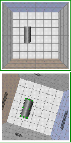
The walls disappear when you quit editing a 3D container. They are not a part of the model you build; they serve as guides only.
The walls and the shadows that the models cast upon them serve as guides; however, they may slow down performance slightly. To temporarily hide the shadows and the walls:
Choose “ Show Wall Shadows” from the Walls menu on the 3D gizmo to turn the shadows off and on. The shadows are on when the box next to “ Show Wall Shadows” is yellow.
Choose “ Show Walls” from the Walls menu on the 3D gizmo to turn the walls off and on. The walls are on when the box next to “ Show Walls” is yellow.
| Note: When the walls are displayed, any models that you create are aligned with the grid lines on the floor and side walls. When you hide the walls, models you create are aligned with the screen. |
As you build models and move them around in the 3D container, you'll notice that the walls automatically expand to make space for the models. The walls do not shrink automatically when you move models away from the walls or delete them from the container. Choose “Shrink to Fit” from the Walls menu to force the walls to shrink to fit the models in the container.
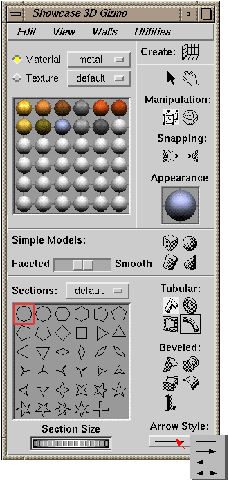
The 3D gizmo has three sets of tools for building models. See Figureá7-19. Each set lets you create a different type of model. The shape of the tool indicates the type of model that you can create.
This list describes the three sets of tools.
One set of tools lets you create simple models—cubes, spheres, cones, and cylinders. You can make such models smooth or jagged and you can scale them. See “Making Simple Models: Cubes, Cylinders, Spheres, and Cones.”
Another set of tools in the 3D gizmo lets you create tubular models. The shape of such a model is determined by the tool you choose—line, circle, rectangle, or arc—and the shape of the cross section—circular, diamond-shaped, or star-shaped, for example. See “Creating Tube-shaped Models.”
The remaining set of tools lets you create beveled models. A bevel gives a model depth and determines the shape of its edges. See “Creating Beveled Models.”
| Note: Many 3D modeling packages let you create models by drawing a line; then rotating that around an axis. For example, you can draw half of a wine glass; then revolve that to create a model of a wine glass. IRIS Showcase does not provide this capability. However, if you installed the inventor_eoe.demo.progs subsystem with your IRIX operating system, you have access to a demo program that provides this capability. The program is called revo and is in the directory /usr/demos/bin. You can copy models you create in revo and paste them into IRIS Showcase. |
This section provides a list of basic instructions for building 3D models.
The 3D gizmo contains three sets of tools for making 3D models. To use any of these tools, you first need to create or edit a 3D container. See “Creating a Container to Hold the 3D Models.”
When you create a simple model, a wireframe representation of the cube, sphere, cylinder, or cone appears as you drag the mouse. When you create a tubular or beveled model, you draw a line, circle, rectangle, or arc. When you release the mouse button, the cross section or bevel gives the model its three-dimensional appearance.
Models display as wireframes if your IRIS workstation doesn't have the necessary graphics capabilities (a z-buffer) to display models in a solid form.
If the walls inside of the 3D container are showing, the wireframe or outline of the model you're creating is aligned with the grid lines on the walls. See Figureá7-20. If the walls are not showing, the model is drawn in an upright position.
Figure 7-20. Two cylinders—one with an upright, front view and one with a slanted view of the 3D container.

You can use the left or middle mouse button to create models. When you use the left mouse button, the model is created in an upright position; when you use the middle mouse button, the model is created perpendicular to the wall or model on which you place the cursor. Figureá7-21 shows the difference.
The 3D gizmo contains tools for making cubes, cylinders, spheres, and cones. To make any of these models, you create or edit a 3D container; then use a tool in the 3D gizmo to make the model.
Create a 3D container to hold the model, or edit an existing 3D container.
For step-by-step instructions on creating a 3D container, see “Creating a Container to Hold the 3D Models.” To make the model in an existing 3D container, place the cursor over a model in the container; then double-click the left mouse button to edit the container.
A thin green line surrounds the container you are editing. Inside the container you see walls with grid marks. The walls help you create and position models in this container. See “About the Walls in the 3D Container.”
Select the cube, cylinder, sphere, or cone tool in the 3D gizmo by clicking it with the left mouse button. See Figureá7-22.
Place the cursor inside of the 3D container that you are editing.
Hold down the left mouse button and drag in any direction.
A wireframe representation of the model appears. If the walls inside of the 3D container are showing, the wireframe is aligned with the grid lines on the walls. If the walls are not showing, the model is drawn upright.
Release the mouse button when the model is the size that you want.
One set of tools in the 3D gizmo is labeled “Tubular.” Select one of these tools, and the palette in the lower portion of the gizmo displays cross sections. When you create a tubular model, you draw a line, circle, rectangle, or arc. When you release the mouse button, the cross section is swept along the line, circle, rectangle or arc. This gives the model its three-dimensional appearance.
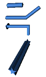
Figureá7-23 shows two models. The model on the left resembles a tube; the model on the right resembles a shooting star. The difference in shape is caused by the cross section. The model on the left has a circular cross section; the model on the right has a star-shaped cross section.
Figure 7-23. Two models—one with a circular cross section, the other with a star-shaped cross section.

For more information on creating tubes, see:
Figureá7-24 shows samples of the types of models you can create using the tubular line tool.
Figureá7-25 shows the tool. You use this tool the way you use the line tool on the Master gizmo. You click the left mouse button to select the starting and intermediate points in the line; you double-click the left mouse button or click the middle mouse button once to end the line.
The step-by-step instructions follow.
Create a 3D container or edit an existing 3D container.
For step-by-step instructions on creating a 3D container, see “Creating a Container to Hold the 3D Models.” To make the model in an existing 3D container, place the cursor over a model in the container; then double-click the left mouse button to edit the container.
A thin green line surrounds the container that you are editing.
Under the label “Tubular,” select the line tool by clicking on it once with the left mouse button. See Figureá7-25.
The lower portion of the gizmo displays a palette of cross sections.
Place the cursor inside of the 3D container that you are editing; then click the left mouse button to begin the model.
Release the mouse button and move the mouse to draw the path of the model.
Double-click the left mouse button to end the model. To create a jagged tube or a tube with many points, continue selecting points with the left mouse button before double-clicking.
The resulting model resembles a tube. The cross section of the model is highlighted in the palette. By default, a circular cross section is active.
| Note: See “Changing a Model's Cross Section” to learn how you can choose a different cross section and change the model's shape. Also see “Making a Bevel Smaller or Larger” to learn how to change the size of the cross section. |
Figureá7-26 shows the arc-shaped tool under the label “Tubular.” You use this tool the way you use the arc tool on the Master gizmo. Press the left mouse button and drag to sweep out a circle; then press the left mouse button and drag to select the portion of the circle to turn into an arc.
Create a 3D container to hold the model, or edit an existing 3D container.
For step-by-step instructions on creating a 3D container, see “Creating a Container to Hold the 3D Models.” To make the model in an existing 3D container, place the cursor over a model in the container; then double-click the left mouse button to edit it.
A thin green line surrounds the container that you are editing.
Under the label “Tubular,” select the arc tool by clicking on it with the left mouse button. See Figureá7-26.
The lower portion of the gizmo displays a palette of cross sections.
Place the cursor inside of the 3D container that you are editing; then press and hold down the left mouse button and drag in any direction. The outline of a circle appears.
Release the mouse button and a straight line appears inside of the circle.
Click down anywhere on the outline. The straight line moves and this becomes the starting point of the arc.
Continue holding down the left mouse button and drag around the circle in either direction. An outline of the arc that you're creating appears.
Release the mouse button when the arc is complete.
The cross section of the model is highlighted in the palette. By default, a circular cross section is active.
| Note: See “Changing a Model's Cross Section” to learn how you can choose a different cross section and change the model's shape. Also see “Making a Bevel Smaller or Larger” to learn how to change the size of the cross section. |
To create a model that resembles a ring or doughnut, you create or edit a 3D container; then use the circle tool under the label “Tubular” in the 3D gizmo. See Figureá7-27.You use this tool the way you use the circle tool on the Master gizmo. Press the left mouse button and drag to sweep out a circle.
Create a 3D container to hold the model, or edit an existing 3D container.
For step-by-step instructions on creating a 3D container, see “Creating a Container to Hold the 3D Models.” To make the model in an existing 3D container, place the cursor over a model in the container; then double-click the left mouse button to edit it.
A thin green line surrounds the container that you are editing.
Under the label “Tubular,” select the circle tool by clicking on it once with the left mouse button. See Figureá7-27.
The lower portion of the gizmo displays a palette of cross sections.
Place the cursor inside of the 3D container that you are editing; then press and hold down the left mouse button and drag in any direction. The outline of a circle appears.
Release the mouse button when the circle is the desired size.
The cross section of the model is highlighted in the palette. By default, the circular cross section is active.
| Note: See “Changing a Model's Cross Section” to learn how you can choose a different cross section and change the model's shape. Also see “Making a Bevel Smaller or Larger” to learn how to change the size of the cross section. |
To make a picture frame, you create or edit a 3D container; then use the rectangle tool under the label “Tubular” in the 3D gizmo to make the model. See Figureá7-28. You use this tool the way you use the rectangle tool on the Master gizmo. You press the left mouse button and drag to sweep out a rectangle.
Create a 3D container to hold the model, or edit an existing 3D container.
For step-by-step instructions on creating a 3D container, see “Creating a Container to Hold the 3D Models.” To make the model in an existing 3D container, place the cursor over a model in the container; then double-click the left mouse button to edit it.
A thin green line surrounds the container that you are editing.
Under the label “Tubular,” select the rectangular tool by clicking on it once with the left mouse button. See Figureá7-28.
The lower portion of the gizmo displays a palette of cross sections.
Place the cursor inside of the 3D container that you are editing; then hold down the left mouse button and drag in any direction. The outline of a rectangle appears.
Release the mouse button when the rectangle is the size you want.
The model resembles a picture frame. The cross section of the model is highlighted in the palette. By default, the circular cross section is active.
| Note: See “Changing a Model's Cross Section” to learn how you can choose a different cross section and change the model's shape. Also see “Making a Bevel Smaller or Larger” to learn how to change the size of the cross section. |
You can change the cross section of tubular models.
Select the model whose cross section you want to change.
To select a model, you must edit the 3D container that holds the model. See “Editing 3D Models.”
Place the cursor over a cross section in the palette; then click the left mouse button once to select it.
The model changes and this becomes the active cross section. Any new tubular models you create will have a cross section of this shape.

Note: The cross section palette only affects models that you create using the tubular modeling tools.
Also see “Changing the Shape of a Cross Section.” It explains how you can modify the shape of a cross section.
You can add arrows to models that you create using one of the tubular modeling tools.
Select the model on which you want to place an arrow.
To select a model, you must edit the 3D container that holds the model. See “Editing 3D Models.”
In the 3D gizmo, place the cursor over the button below the label “Arrow Style”; then press the left mouse button to reveal a pop-up menu of arrow styles. See Figureá7-29.

Note: This menu only affects models that you create using the tubular modeling tools. You cannot place an arrow on the end of simple models, beveled models, or other types of models you import.
Choose an arrow style from the pop-up menu; then release the mouse button.
The arrow style you choose becomes active. For example, select the icon for arrows at both ends, and any new tubular models that you create will have arrows at both ends.
You can cap and uncap models you create using the tubular or beveled modeling tools. An uncapped model is open-ended like a straw; a capped model is closed, like a cylinder.
By default, all tubular models and most beveled models are capped. Beveled arcs and lines are the exceptions; they are uncapped by default.
To put a cap on a model, select the model; then choose “ Cap Model” from the Edit menu on the 3D gizmo.
To remove the cap from a model, select the model; then choose “ Uncap Model” from the Edit menu on the 3D gizmo.
| Note: You cannot place a cap on or remove a cap from models you create using the simple modeling tools. |
“Changing the Shape of Graphics Objects” explains how you can add, delete, and move points to change the shape of 2D lines, rectangles, circles, and other 2D objects. Similarly, you can add or delete points to a tube to change the path it follows.
Place the cursor over the model whose shape you want to change; then double-click the left mouse button to edit it. You can change only the shape of models that you created by using one of the tubular or beveled modeling tools.
The model displays as a wireframe; small green squares mark the points you can edit.
Once you are editing the model, you can add, delete, and move points using the techniques described in “Changing the Shape of Graphics Objects.” Please note one exception. You cannot press the left mouse button and drag to select multiple points.
You can skip the first several steps in these sections since you're already editing the model.
When you finish editing the model, click the left mouse button in an empty part of the 3D container or choose “Done Editing Model” from the Edit menu on the 3D gizmo.
“Resizing 3D Models” explains how you can make a 3D model smaller or larger; this section explains how you can change the size of the cross section.
Select the model whose cross section you want to make smaller or larger.
To select a model, you must edit the 3D container that holds the model. See “Editing 3D Models.”
Place the cursor over the thumbwheel at the bottom of the 3D gizmo; then press the left mouse button and drag to spin the wheel.
Drag the cursor to the left to make the cross section smaller.
Drag the cursor to the right to make the cross section larger.

Note: You might see a delay between the time you spin the thumbwheel and the time the cross section changes. The change isn't always immediate.
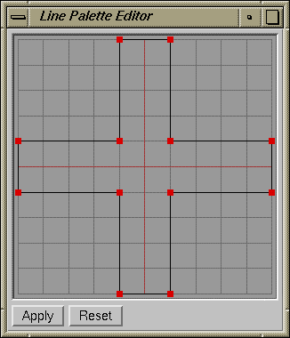
You can change the shape of a cross section using the cross section editor. This editor appears when you place the cursor over a cross section in the palette and then double-click the left mouse button.
Place the cursor over the item in the palette that you want to modify; then double-click the left mouse button. If the cross section palette isn't already displayed, select one of the tubular modeling tools.
The cross section editor appears. It displays the cross section you're going to modify. See Figureá7-30.
Change the shape by adding, deleting, and moving points on the cross section.
You cannot press the left mouse button and drag to select multiple points. With this exception, the instructions in “Changing the Shape of Graphics Objects” explain how to add, delete, and move points.
| Note: When you edit a cross section in the palette, a file named .crossSections appears in your home directory. This an ASCII file that describes the cross section according to the Inventor file format. Developers who are familiar with the Inventor file format can change cross sections by editing this file. |
IRIS Showcase provides several palettes of cross sections. One palette is labeled “default”; it contains a set of existing palettes. Another palette is labeled “custom”; initially it is blank. You can fill it with cross sections that you create.
Display the cross section palette in the 3D gizmo.
If it isn't already displayed, select one of the tubular modeling tools.
Place the cursor over the button next to the label “Sections”; then press the left mouse button to reveal a menu.
Choose “custom” from the pop-up menu.
An empty palette appears.
Place the cursor over a slot in the palette; then double-click the left mouse button.
A red box outlines each slot in the palette. Double-clicking opens the cross section editor. By default, the editor displays a triangle.
Follow the instructions listed in step 2 in “Changing the Shape of a Cross Section.”
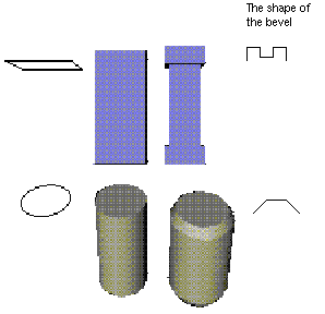
When you create a beveled model, you draw a line, circle, rectangle, or arc. When you release the mouse button, the bevel gives the model its three-dimensional appearance. For example, in Figureá7-31, a straight bevel turns the square into a beam; the bevel shown turns the beam into a pillar. A straight bevel turns the circle into a cylinder; the bevel shown turns the cylinder into a soda pop can.
| Note: The cylinder in this example was created using the beveled circle tool. You cannot apply bevels to models you create using the simple modeling tools. |
For more information on creating beveled models, see:
Figureá7-28 shows the beveled line tool in the 3D gizmo. You can use this tool to make models of many different shapes—flat sheets, peaked rooftops, triangles, and more. You use the tool the way you use the line tool on the Master gizmo. Click the left mouse button to select the starting and intermediate points in the line; double-click the left mouse button to end the line. The bevel turns the line into a three-dimensional model. The step-by-step instructions follow:
Create a 3D container to hold the model, or edit an existing 3D container.
For step-by-step instructions on creating a 3D container, see “Creating a Container to Hold the 3D Models.” To make the model in an existing 3D container, place the cursor over a model in the container; then double-click the left mouse button to edit it.
A thin green line surrounds the container that you are editing. Inside the container you see walls with grid marks. The walls help you create and position models in this container. See “About the Walls in the 3D Container.”
Under the label “Beveled,” select the line tool by clicking it with the left mouse button. See Figureá7-28.
The lower portion of the gizmo displays a palette of bevels.
Place the cursor inside of the 3D container that you are editing; then click the left mouse button to begin the model.
Release the mouse button and move the mouse to draw the path of the model.
Double-click the left mouse button to end the model. To create a jagged line, continue selecting points with the left mouse button before double-clicking.
Depending on the path the line follows, the resulting model resembles a flat sheet, a peaked roof, or a triangle, for example.
The bevel of the model is highlighted in the palette. By default, the straight line is active. You can choose a different bevel to change the shape of the model. See “Changing the Bevel a Model Uses.”
Figureá7-32 shows the beveled circle tool in the 3D gizmo. You can use this tool to make cylindrical models. You use the tool the way you use the circle tool on the Master gizmo. Press the left mouse button and drag to sweep out a circle. The bevel turns the circle into a three-dimensional model.
The step-by-step instructions follow:
Create a 3D container to hold the model, or edit an existing 3D container.
For step-by-step instructions on creating a 3D container, see “Creating a Container to Hold the 3D Models.” To make the model in an existing 3D container, place the cursor over a model in the container; then double-click the left mouse button to edit it.
A thin green line surrounds the container you are editing.
Under the label “Beveled,” select the circle tool by clicking it with the left mouse button. See Figureá7-32.
The lower portion of the gizmo displays a palette of bevels.
Place the cursor inside of the 3D container that you are editing; then press and hold down the left mouse button and drag in any direction. The outline of a circle appears.
Release the mouse button when the circle is the desired size.
The model appears. The bevel of the model is highlighted in the palette. By default, the straight line is active. You can choose a different bevel to change the shape of the model. See “Changing the Bevel a Model Uses.”
Figureá7-33 shows the beveled rectangle tool in the 3D gizmo. You can use this tool to make rectangular models.You use the tool the way you use the rectangle tool on the Master gizmo. Press the left mouse button and drag to sweep out a rectangle. The bevel turns the rectangle into a three-dimensional model.
The step-by-step instructions follow.
Create a 3D container to hold the model, or edit an existing 3D container.
For step-by-step instructions on creating a 3D container, see “Creating a Container to Hold the 3D Models.” To make the model in an existing 3D container, place the cursor over a model in the container; then double-click the left mouse button to edit it.
A thin green line surrounds the container that you are editing.
Under the label “Beveled,” select the rectangle tool by clicking it with the left mouse button. See Figureá7-33.
The lower portion of the gizmo displays a palette of bevels.
Place the cursor inside of the 3D container that you are editing; then press and hold down the left mouse button and drag in any direction. The outline of a rectangle appears.
Release the mouse button when the rectangle is the desired size.
The model appears. The bevel of the model is highlighted in the palette. By default, the straight line is active. You can choose a different bevel to change the shape of the model. See “Changing the Bevel a Model Uses.”
Figureá7-34 shows the beveled arc tool in the 3D gizmo. You use the tool the way you use the arc tool on the Master gizmo. Press the left mouse button and drag to sweep out a circle; then press the left mouse button and drag to select the portion of the circle to turn into an arc.
Create a 3D container to hold the model, or edit an existing 3D container.
For step-by-step instructions on creating a 3D container, see “Creating a Container to Hold the 3D Models.” To make the model in an existing 3D container, place the cursor over a model in the container; then double-click the left mouse button to edit it.
A thin green line surrounds the container that you are editing.
Under the label “Beveled,” select the arc tool by clicking it with the left mouse button. See Figureá7-34.
The lower portion of the gizmo displays a palette of bevels. By default, the straight line is highlighted.
Place the cursor inside of the 3D container that you are editing; then press and hold down the left mouse button and drag in any direction. The outline of a circle appears.
Release the mouse button and a straight line appears inside of the circle.
Click anywhere on the outline. This becomes the starting point of the arc.
Continue holding down the left mouse button and drag around the circle in either direction. An outline of the arc that you're creating appears.
Release the mouse button when the arc is the desired size.
The model appears. The bevel of the model is highlighted in the palette. By default, the straight line is active. You can choose a different bevel to change the shape of the model. See “Changing the Bevel a Model Uses.”
You can change the shape of a model by changing the bevel it uses.
Select the model whose bevel you want to change.
To select a model, you must edit the 3D container that holds the model. See “Editing 3D Models.”
When you select a beveled model, the palette in the 3D gizmo automatically changes to display the bevel palette.
Place the cursor over a bevel in the palette; then click the left mouse button to select it.
The model changes and this becomes the active bevel. Any new beveled models you create will have a bevel of this shape.
Also see “Changing the Shape of a Bevel in the Palette.” It explains how you can modify the shape of a bevel.
You can cap and uncap models that you create using the tubular or beveled modeling tools. An uncapped model is open-ended, like a can with the top and bottom removed; a capped model is closed, like a cylinder.
By default, most beveled models are capped. Beveled arcs and lines are the exception; they are uncapped by default.
To put a cap on a model, select the model; then choose “ Cap Model” from the Edit menu on the 3D gizmo.
To remove the cap from a model, select the model; then choose “ Uncap Model” from the Edit menu on the 3D gizmo.
| Note: You cannot place a cap on or remove a cap from models you create using the simple modeling tools. |
“Changing the Shape of Graphics Objects” explains how you can add, delete, and move points to change the shape of 2D lines, rectangles, circles, and other 2D objects. Similarly, you can add or delete points to change the shape of a beveled model.
Place the cursor over the model whose shape you want to change; then double-click the left mouse button to edit it. You can change only the shape of models you created using one of the tubular or beveled modeling tools.
The model displays as a wireframe; small green squares mark the points you can edit.
Once you are editing the model, you can add, delete, and move points using the techniques described in “Changing the Shape of Graphics Objects.” Please note one exception. You cannot press the left mouse button and drag to select multiple points.
When you finish editing the model, click the left mouse button in an empty part of the 3D container or choose “Done Editing Model” from the Edit menu in the 3D gizmo.
“Resizing 3D Models” explains how you can make a 3D model smaller or larger; this section explains how you can change the size of the bevel.
Select the model whose bevel you want to make smaller or larger.
To select a model, you must edit the 3D container that holds the model. See “Editing 3D Models.”
Place the cursor over the thumbwheel at the bottom of the 3D gizmo; then press the left mouse button and drag to spin the wheel.
Drag the cursor to the left to make the bevel smaller.
Drag the cursor to the right to make the bevel larger.

Note: You might see a delay between the time you spin the thumbwheel and the time the bevel changes. The change isn't always immediate.
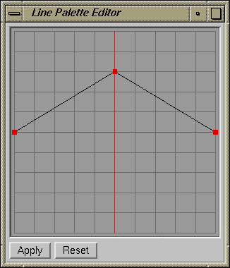
You can change the shape of a bevel by using the bevel editor. This editor appears when you place the cursor over an item in the bevel palette, and then double-click the left mouse button.
Place the cursor over the item in the palette that you want to modify; then double-click the left mouse button. If the bevel palette isn't already displayed, select one of the beveled modeling tools.
The bevel editor appears. It displays the bevel that you're going to modify. See Figureá7-35.
Change the shape by adding, deleting, and moving points on the bevel.
You cannot press the left mouse button and drag to select multiple points. With this exception, the instructions in “Changing the Shape of Graphics Objects” explain how to add, delete, and move points.
| Note: When you edit a bevel in the palette, a file named .bevels appears in your home directory. This an ASCII file that describes the bevel according to the Inventor file format. Developers who are familiar with the Inventor file format can change bevels by editing this file. |
IRIS Showcase provides several palettes of bevels. One palette is labeled “default”; it contains a set of existing palettes. Another palette is labeled “custom”; initially it is blank. You can fill it with bevels that you create.
Display the bevel palette in the 3D gizmo.
If it isn't already displayed, select one of the beveled modeling tools.
Place the cursor over the button next to the label “Bevels”; then press the left mouse button to reveal a menu.
Choose “custom” from the pop-up menu.
An empty palette appears.
Place the cursor over a slot in the palette; then double-click the left mouse button.
A red box outlines each slot in the palette. Double-clicking opens the bevel editor. By default, the editor displays a straight line.
Follow the instructions listed in step 2 in “Changing the Shape of a Bevel in the Palette.”
The 3D gizmo contains a tool for typing 3D text. It's one of the beveled modeling tools. The resulting text is a 3D model that you can manipulate like other models and edit like other text.
Open the 3D gizmo by choosing “ 3D” from the Gizmos menu.
Create a 3D container to hold the model, or edit an existing 3D container if you want to place the model in an existing container.
To create a 3D container, click the button in the upper right corner of the 3D gizmo. For step-by-step instructions on creating a 3D container, see “Creating a Container to Hold the 3D Models.”
To draw the model in an existing 3D container, place the cursor over a model in the container; then double-click the left mouse button to edit the container.
Click the text tool in the 3D gizmo. See Figureá7-36.
Place the cursor inside of the 3D container that you are editing; then click the left mouse button. A 3D text cursor appears.
Begin typing. Each character appears as you type it. The line of characters expands to the right.

Note: You see only the characters that fit within the bounds of the 3D container. You can continue typing even though you cannot see the characters that go beyond the right edge of the container. Press <Enter> when you want to begin a new line.
When you finish typing, click the left mouse button in an empty part of the 3D container or select another tool from the Master or 3D gizmo.

Note: If some characters in the text model disappear beyond the right edge of the container, you can make them visible by changing the font size, resizing or moving the 3D text model, or panning within the container. See also “Changing Your View of 3D Models.”
You can modify text models in several ways. You can change the bevel a text model uses to make it look fancier, you can edit the text to correct mistakes or add new text, and you can change the font, size, and color of text.
For more information on modifying text models, see:
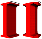
By default, the edges of a 3D text model are straight. You can change the shape of the edge to create a fancier looking text model. Figureá7-37 shows a model of the letter “I” with a straight edge and with a beveled edge. The black line above each “I” shows the shape of the bevel.
To create a text model with beveled edges:
Select the 3D text model. The 3D gizmo displays a palette of bevels in the lower portion of the gizmo.
To select a model, you must edit the 3D container that holds the model. See “Editing 3D Models.”
Place the cursor over the bevel you want to apply; then click the left mouse button.
The text model changes. This bevel becomes active. Any text models or models you create using the beveled circle, line, arc, or square tool will have edges of this shape.
You edit a 3D container when you want to add models or change the appearance of models already in the container. You can also edit a text model if you want to add or delete characters.
Place the cursor over the 3D container that contains the text model you want to edit; then double-click the left mouse button. A light-green box surrounds the container.
Place the cursor over the text model you want to edit; then double-click the left mouse button again.
A light-green box surrounds the model.
Once you are editing the text model you can add and delete characters using the techniques described in “Adding Text” and “Deleting Text.” You can skip the first several steps in these sections since you're already editing the model.
When you finish editing the text, click the left mouse button in an empty part of the 3D container or select another tool from the Master or 3D gizmo.
You can use the font controls in the Master gizmo to change the font used in a 3D text model.
Select the 3D text model.
To select a model, you must edit the 3D container that holds the model. See “Editing 3D Models.”
Go to the Master gizmo.
If it's buried underneath other windows, pop it to the top by choosing “Master” from the Gizmos menu.
Place the cursor next to the label “Font Family”; then press the left mouse button to reveal a pop-up menu of available fonts.
Choose a font from the pop-up menu; then release the mouse button.
The name of the selected font appears on the button, and the text model changes to that font.
| Note: All of the characters in a 3D text model must use the same font. You cannot select individual letters and change their fonts. As a workaround, you can make each character or set of characters a separate text model. |
You can use the controls at the bottom of the Master gizmo to make a font bold, italic, or underlined.
Select the 3D text model.
To select a model, you must edit the 3D container that holds the model. See “Editing 3D Models.”
Go to the Master gizmo.
If it's buried underneath other windows, pop it to the top by choosing “Master” from the Gizmos menu.
Place the cursor next over the box next to the labels “Bold,” “Italic,” or “Underline”; then click the left mouse button. A red checkmark indicates which styles are selected.
| Note: All of the characters in a text model must be of the same style. You cannot select individual letters and make them bold, italic, or underlined. As a workaround, you can make each character or set of characters a separate 3D text model. |
You can use the font controls in the Master gizmo to change the size of text used in a 3D text model. Additionally, you can resize the model following the instructions in “Resizing 3D Models.”
This section describes how you use the controls on the Master gizmo.
Select the 3D text model.
To select a model, you must edit the 3D container that holds the model. See “Editing 3D Models.”
Go to the Master gizmo.
If it's buried underneath other windows, pop it to the top by choosing “Master” from the Gizmos menu.
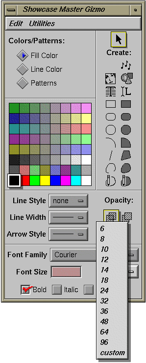
Place the cursor next to the label “Font Size”; then press the left mouse button to reveal a pop-up menu of available sizes. See Figureá7-38.
Choose a size from the pop-up menu; then release the mouse button.
The selected size appears on the button, and the text model changes to that size.
| Note: All of the characters in a 3D text model must be the same size. You cannot select individual letters and change their sizes. As a workaround, you can make each character or set of characters a separate text model. |
In many cases, 3D models behave like objects. You can delete 3D models, group and ungroup 3D models, and create scripts for 3D models. For instructions, see Chapterá3, “Working with Objects,” and “Using HyperScripts.”
For information on manipulating models, see:
Chapterá3, “Working with Objects,” explains how to select objects. The same techniques apply to models inside of the 3D container, with three exceptions:
To select a model in the container, you must first edit the container. Place the cursor over a model in the container; then double-click the left mouse button. A green outline surrounds the container, indicating you are editing it.
To select a model in the container that you're editing, place the cursor over the model; then click the left mouse button. (If the cursor resembles a hand, click the arrow icon in the 3D gizmo to signal that you want to select models.)
You cannot select models by pressing the left mouse button and sweeping out a box that surrounds the models. To select several models, press the <Shift> key.
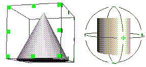
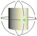
When you select a model, the model is surrounded by a bounding box or a trackball. Both of these are called manipulators. They let you manipulate the selected model in various ways. The bounding box shows the six sides, or faces, of a model—the top and bottom, left and right, and front and back sides. The trackball forms a sphere around the model. You can use the trackball to rotate the model. See Figureá7-39.
| Note: To display a bounding box on selected models, click the cube-shaped icon under the label “Manipulation” in the 3D gizmo. To display a trackball on selected models, click the sphere-shaped icon under the label “Manipulation.” |
You edit a 3D container when you want to add models or change the appearance of models already in the container. You can also edit certain types of models in the container. This list explains how to edit 3D container and models.
You edit the 3D container the way that you edit any other object on the page. Place the cursor over a model in the container; then double-click the left mouse button. Or, select the container; then choose “Edit Object” from the Edit menu. A light-green rectangle surrounds the container.
To edit a 3D text model or a model that you create by using the tubular or beveled modeling tools in the 3D gizmo, place the cursor over the model; then double-click the left mouse button. Your other option is to select the model; then choose “Edit Model” from the Edit menu on the 3D gizmo or use the keyboard shortcut, <Alt>-E. A light-green rectangle surrounds the model.
To quit editing a model, choose “Done Editing Model” from the Edit menu, select another tool from the 3D or Master gizmo, or place the cursor over an empty area in the 3D container, then click the left mouse button.
Objects appear larger or smaller when you resize them. In the 3D container, a model can appear to change size for several reasons:
You resize the model and it is smaller or larger. See “Changing the Size of All Models in a 3D Container” and “Resizing Selected Models in the 3D Container.”
You zoom in or out. Models look larger or smaller depending on how close they are to you. See “Changing Your View of 3D Models.”
You move the model in the container. The farther away the model, the smaller it looks; the closer the model, the larger it looks. See “Moving 3D Models.”
Resizing a 3D container makes all of the models inside of it appear larger or smaller. It does not give you more or less space within the container.
The 3D container is like any other object on the IRIS Showcase page. To resize it:
Select the 3D container that you want to stretch or shrink.
Place the cursor over one of the small boxes outlining the container.
Hold down the left mouse button and drag the cursor to enlarge or reduce the container.
A red outline shows you how you're resizing the container.
Release the mouse button when you're satisfied with the new size.
The models inside appear larger or smaller.
You change the size of a 3D model nearly the same way you change the size of a 2D graphics object.
Select the model whose size you want to change.
To select a model, you must edit the 3D container that holds the model. See “Editing 3D Models.”

Note: If a trackball appears around the selected model, click the cube-shaped icon under the label “Manipulation” in the 3D gizmo. You need to use the bounding box to resize the model. Place the cursor over one of the small green squares outlining the bounding box.
Place the cursor over the middle square on a side to make the model larger or smaller in one dimension.
Place the cursor over one of the corner squares to make the model larger or smaller in two dimensions (height and width, for example).
Place the cursor over a corner square and press the <Shift> key to adjust the height, width, and depth of the model.
Hold down the left mouse button and drag the cursor to enlarge or reduce the model.
Release the mouse button when you're satisfied with the new size.
Use the “ Copy” and “ Paste” commands in the main Edit menu to copy and paste 3D models within and between 3D containers.
Select the model that you want to copy.
To select a model, you must edit the 3D container that holds the model. See “Editing 3D Models.” A bounding box or trackball appears around the selected model.
Choose “ Copy” from the Edit menu.
If you want to paste the copy into another 3D container, edit that container.
Choose “ Paste” from the Edit menu.
If you're still editing a 3D container, an outline of the copy appears in that container. Click the left mouse button to place the copy.
If you are not editing a 3D container, IRIS Showcase creates a new container for you and places the model in it. (You can resize this container and place it on the page like you do any other 3D container.)
| Note: If you installed the inventor_eoe.demo.progs subsystem, you have access to revo and textomatic, two 3D demo programs in the /usr/demos/bin directory. You can copy models you create in the demo programs and paste them into IRIS Showcase. |
The models you create inside of the container are three-dimensional. They have height, width, and depth, and you can move them in three dimensions—left or right, up or down, and toward or away from you. If you move the model up, you see the under side of the model. If you move the model down, you see the top side of the model.
You can use one of two techniques to move a model. You can use the shadows the model casts onto the walls or you can use the bounding box that appears when you select a model.
| Note: The models appear in wireframe when you move them. This lets you move the models more smoothly and quickly. To maintain the solid appearance, the texture, and the shadows as you move models, turn off this feature by choosing “ Move Low Res” from the Edit menu on the 3D gizmo. “Move Low Res” is on when the box next to it is yellow. |
When you select a model, it casts a shadow onto the walls in the 3D container. You can use these shadows to move the model.
Select the model that you want to move.
To select a model, you must edit the 3D container that holds the model. See “Editing 3D Models.”
The selected model casts a shadow onto the walls. See Figureá7-40.

Note: If the walls and shadows are not displayed, choose “ Show Walls” and “ Show Wall Shadows” from the Walls menu on the 3D gizmo. Decide the direction in which you want to move the model—up or down, left or right, or toward or away from you.
A model's shadow can help you determine the direction in which to move the model. For example, suppose you're trying to position one model near another model in the container. Select both models; then compare the location of the shadows.
Place the cursor over one of the shadows. The grid lines on the wall show the direction in which the shadow on that wall lets you move the model. For example:
Place the cursor over the shadow on the back wall if you want to move the model left and right or up and down.
Place the cursor over the shadow on one of the side walls to move the model up and down or away from and closer to you.
Place the cursor over the shadow on the floor or ceiling to move the model left and right or away from or closer to you.
Press the left mouse button and drag the cursor. An outline of the model moves with the cursor.

Note: Each shadow lets you move the model in two directions. For example, the shadow on the back wall lets you move the model left and right or up and down. Press the <Shift> key and the left mouse button to constrain movement to one direction—either left and right or up and down. Release the mouse button when the model is positioned correctly.
You can move a model by using the bounding box that surrounds a model.
Select the model that you want to move.
To select a model, you must edit the 3D container that holds the model. See “Editing 3D Models.”
A bounding box appears around the selected model. The bounding box shows the six sides, or faces, of a model—the top and bottom, left or right, and front and back sides. Additionally, the selected model casts a shadow onto the walls.

Note: If a trackball appears around the selected model, you can turn it off by clicking the cube-shaped icon under the label “Manipulation” in the 3D gizmo. Decide the direction in which you want to move the model—up or down, left or right, or toward or away from you.
Place the cursor over one side of the bounding box. The edges of the bounding box show the direction in which that face lets you move the model. See Figureá7-41.
Figure 7-41. Arrows showing how different faces of the bounding box let you move a model in different directions.
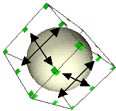
Press the left mouse button and drag the cursor. An outline of the model moves with the cursor.

Note: Each face of the bounding box lets you move the model in two directions. For example, one face will let you move the model left and right and up and down. Press the <Shift> key and the left mouse button to constrain movement to one direction—either left and right or up and down. Release the mouse button when the model is positioned correctly.
This section describes two techniques you can use to align models. The first section describes how you can use shadows to align models; the second section describes how you can use the snapping tools to align models.
Selected models cast shadows onto the walls in the 3D container. You can use these shadows to align models visually.
Select the models that you want to align by pressing the <Shift> key while clicking on the models. The selected models cast shadows onto the walls.
To select a model, you must edit the 3D container that holds the model. See “Editing 3D Models.”

Note: If the walls and shadows are not displayed, choose “ Show Walls” and “ Show Wall Shadows” from the Walls menu on the 3D gizmo. If some of the shadows are out of view, press the <Alt> key and middle mouse button; then slowly move the cursor toward the top of the 3D container.
This lets you zoom out. When you release the mouse button, the shadows reappear. You might have to experiment a few times to get the right view.
Compare the location of the shadows that the selected models cast. To align the models, you move the shadows, as described in “Using Shadows to Move 3D Models.”
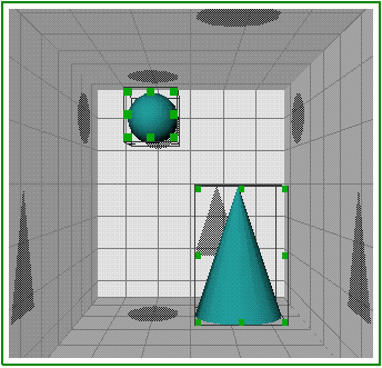
For example, in Figureá7-42, suppose you want to align the left edges of the cone and sphere. Place the cursor over the shadow the cone casts onto the back wall; then drag the shadow until its left edge appears to be lined up with the shadow that the sphere casts onto the floor.
“Snapping One 3D Model to Another” explains how you snap one model to another. This section provides a hint for aligning 3D models.
Suppose you want to align the left edges of several models.
Make a cube using the simple modeling tools.
Use the snapping tools to attach the models to one side of the cube. See “Snapping One 3D Model to Another” for instructions.
Once you've snapped all of the models to the cube, delete the cube.
You can rotate models using a trackball.
Select the model that you want to rotate.
To select a model, you must edit the 3D container that holds the model. See “Editing 3D Models.”
Click the sphere-shaped icon under the label “Manipulation” in the 3D gizmo. See Figureá7-43.
A trackball appears around the model. See Figureá7-44.
Place the cursor over the model; then press the left mouse button and drag the mouse. The model begins to rotate.
Do not place the cursor over the green arrows. Doing so moves the trackball. See “Moving the Trackball.”
Place the cursor anywhere on the sphere to rotate freely.
Place the cursor over a line in the sphere to constrain the rotation to that direction.
Release the mouse button when the model is at the angle you want.
The trackball forms a sphere around the model. See Figureá7-44. By default, the center of the sphere is aligned with the center of the model. This means that the model rotates about its center point. You can move the trackball if you want the model to rotate around a different point.
To move the trackball:
Place the cursor over the green arrows that appear in several places on the trackball.
Press the left mouse button and drag the mouse.
The rotation handles move.

Note: Press the <Shift> key if you want the center of the trackball to snap to the center, corners, and edges of the model as you move it. Release the mouse button when the trackball is positioned where you want it.
When you rotate the model, it rotates about the center of the trackball in its new position.
The 3D gizmo contains two icons that let you attach one model to another. For example, suppose you've drawn a wing and you need to attach it to the body of the model airplane. You can use the snapping tools.
If possible, position the models so you can see the sides that you want to connect. See “Rotating 3D Models” or “Spinning the Scene”
Under the label “Snapping” in the 3D gizmo, you see a pair of icons. Click the left icon; it's the “snap from” icon. See Figureá7-45
.Place the cursor over the point on the model that you want to attach to another model; then press and hold the left mouse button.
A red arrow appears on the model. It moves as you move the cursor. This arrow shows the area of model that will be attached to the other model.
Release the mouse button when the arrow is positioned where you want it.
Select the model to which you want to snap the first model.
If the model you want to snap to is in view, select the model. The first model snaps into position.
If the model you want to snap to is not visible, you will need to change your view of the models. See “Using Commands on the View Menu to Change Your View of Models” and “Using the Viewer Tool”
If you use the Viewer tool, you have an additional step. You need to click the “snap to” icon (the right icon in the pair) before selecting the model to which you want to snap.
| Note: The right icon, the “snap to” icon, in the pair of snapping icons lets you reverse the sequence. The first model you select is the one to which the second model you select will snap. |
You can view 3D models from all different angles—front, back, top, bottom, left, right, or any angle in between. To change your view of the models, you rotate the scene inside of the 3D container. For example, suppose you place a model airplane inside of a glass box. Flip the box upside down and you view the bottom of the model plane.
You can also change your view by zooming and panning. When you zoom, you make models look larger or smaller by moving them farther away from or closer to you. When you pan, you change the portion of the scene you are viewing.
This sections describes three basic methods for changing your view:
The View menu contains commands that let you view models from different directions, set a home view, view all models or the selected models, and change the lens through which you view the models.
Six of the commands on the View menu let you view models from fixed directions—from the top, bottom, left, right, front, or back of the container.
Place the cursor over the 3D container; then double-click the left mouse button to edit the container. A light-green box surrounds the container.
On the View menu in the 3D gizmo, choose one of the six commands listed in the middle of the menu.
The “ Set Home” command lets you choose a custom view. When you choose “ Set Home,” you save the direction and the distance from which you're viewing the models. To return to the home view, choose “View Home.”
| Note: By default, the home view is equivalent to the front view. |
The “View All” command lets you quickly zoom out so that you can see all of the models in the container. Choose “View All” from the View menu on the 3D gizmo if:
Some of the models you've created are only partially visible or are completely out of view.
You want to center the scene within the 3D container.
| Note: The “ View All” command does not change the actual size of any models; it moves them farther away. |
The “ View Selection” command shifts the scene so the selected model is centered in the 3D container.
Select the model(s) around which you want to center the view.
To select a model, you must edit the 3D container that holds the model. See “Editing 3D Models.”
Choose “View Selection” from the View menu on the 3D gizmo.
The contents of the container shift. The selected model appears in the center.
Photographers switch camera lenses to take different types of pictures. They might use a telephoto lens to take close-up shots with little to no perspective, or a wide angle lens to take panoramic shots with a great deal of perspective. As a finishing touch, you can use one of the Lens commands to achieve a similar affect in your 3D scene.
Figureá7-46 shows the affects of choosing each lens. “Wide Lens” makes the back edge of the table top appear fairly narrow; “Telephoto Lens” makes the back edge of the table top appear very wide.
| Note: When you change to a different lens, models appear smaller or larger because the viewing angle of the lens is different. When you use a narrow lens (telephoto), a model appears larger because proportionally it takes up more of the viewing area. When you use a wide lens, a model appears smaller. Proportionally, it takes up less of the viewing area. |
The walls that appear in the 3D container make it easy for you to view models from different directions and zoom or pan.
The commands on the View menu let you view models from six fixed directions. This section describes a technique that lets you interactively change the view.
If you're not already editing the 3D container, place the cursor over the 3D container; then double-click the left mouse button to edit the container.
A light-green box surrounds the container when you're editing it.
If the walls are not displayed, turn them on by choosing “Show Walls” from the Walls menu on the 3D gizmo.
Place the cursor over one of the walls, making sure the cursor isn't over a model or a shadow.
Press the left mouse button. A black line and a circle appear.
Each wall lets you spin the scene in a different direction. The circle shows the way in which you'll spin the scene; the black line represents the axis around which you will rotate.
Continue pressing the mouse button and drag the mouse.
The scene spins inside of the container.
Release the mouse button when you have the desired view of the models.
When the walls are displayed, you can use the middle mouse button to zoom and pan.
If you're not already editing the 3D container, place the cursor over the 3D container; then double-click the left mouse button to edit the container.
A light-green box surrounds the container when you're editing it.
If the walls are not displayed, turn them on by choosing “Show Walls” from the Walls menu on the 3D gizmo.
Place the cursor over one of the walls, making sure the cursor isn't over a model.
Press the middle mouse button, and then move the cursor. The scene moves parallel to the wall on which you place the cursor. The result: you pan or zoom. See Figureá7-47.
| Note: The “Pan” commands on the main View menu move the entire page. The “Zoom” commands on the main View menu make the entire page appear larger or smaller. The techniques described above affect models in the 3D container. |
The Viewer tool on the 3D gizmo puts you in a special viewing mode. When you press the mouse button and drag the mouse, you change your view of the 3D models.
To go into viewing mode:
If you're not already editing the 3D container, place the cursor over the 3D container; then double-click the left mouse button to edit the container.
A light-green box surrounds the container when you're editing it.
Select the Viewer tool in the 3D gizmo by clicking it with the left mouse button. The Viewer tool resembles a hand; see Figureá7-48.
| Tip: Press and hold the <Alt> key to go into viewing mode temporarily. For example, press the <Alt> key and the left mouse button; then drag the cursor to spin the scene inside of the container. When you release the <Alt> key, you're returned to select mode. |
“Spinning the Scene” explains how you can use the walls to change your view of 3D models. This section describes how you do this while you're in viewing mode. (See “Using the Viewer Tool” to learn how to go into viewing mode.)
Move the cursor inside of the 3D container; then press the left mouse button and drag the mouse. The scene spins.

Note: Press the <Shift> key and the left mouse button to constrain the rotation to one direction. A small circle with an arrow appears. This indicates the direction in which the scene will spin. Release the mouse button when you have the desired view of the models.
While in viewing mode, move the cursor inside of the 3D container; then press the middle mouse button and drag the mouse. Move the cursor up and you appear to push the models away from you; move the cursor down and you appear to pull the models closer to you.
(See “Using the Viewer Tool” to learn how to go into viewing mode.)
Panning lets you change the portion of the scene you're viewing. While you're in viewing mode, move the cursor inside of the 3D container; then press the <Shift> key and middle mouse button and drag the mouse. The scene shifts left and right and up and down. (See “Using the Viewer Tool” to learn how to go into viewing mode.)
This topic describes how you modify 3D models. For information, see:
IRIS Showcase lets you display models as solid models or as wireframe models. To display the model as a wireframe:
Select the model that you want to display as a wireframe.
To select a model, you must edit the 3D container that holds the model. See “Editing 3D Models.”
Choose “ Make Wireframe” from the Edit menu on the 3D gizmo.
To make a wireframe model solid, choose “Make Solid” from the Edit menu on the 3D gizmo.
| Note: If your IRIS workstation doesn't have the graphics capabilities to display models in a solid form, it will display them as wireframe representations. |
You can make a simple 3D model (cube, sphere, cone, or cylinder) smooth or jagged. For example, you can make a cone then change it into a pyramid-shaped model by using the slider in the 3D gizmo.
To make a model smooth or jagged:
Select the model you want to change.
To select a model, you must edit the 3D container that holds the model. See “Editing 3D Models.”
Use the slider under the label “Simple Models.”
To make the model as jagged as possible, drag the slider to the left-most edge of the scroll bar.
To make the model as smooth as possible, drag the slider to the right-most edge of the scroll bar.

Note: This slider only affects models that you create using the simple modeling tools. It does not affect models you create using one of the tubular or beveled modeling tools.
You can change the color of a 3D model by choosing a color from the color palette in the Master gizmo. You can also change a color by altering the material from which the model is made. See also “Changing the Material of a 3D Model.” To change the color using the color palette:
Select the model whose color you want to change.
To select a model, you must edit the 3D container that holds the model. See “Editing 3D Models.”
Go to the Master gizmo.
If it's buried underneath other windows, pop it to the top by choosing “Master” from the Gizmos menu.
Click the button next to the label “Fill Color.” A blue triangle indicates it is selected.
Click the left mouse button on the color you want to select.
The color is outlined and the model changes to the new color. In the 3D gizmo, the sphere labeled “Appearance” changes to show this color.

Note: The color you select becomes the active interior color. This means that any new objects you create—any text you type, rectangles you draw, or models you build—will be filled with this color.
A model's appearance is determined by the material from which you build it. For example, if you're building a model airplane, you might choose to build it out of metal, plastic, or wood.
In IRIS Showcase, the material determines:
the color of the model
whether the model looks plastic or metallic
whether the model appears rough or smooth
whether the model is opaque or transparent
By adjusting the settings, you can create a variety of materials. IRIS Showcase includes several sample palettes and a custom palette that you can fill with materials you create.
A material can look plastic or metallic, rough or smooth, and opaque or transparent. The difference in appearance depends on the way the material reflects light.
A material looks plastic or metallic, depending on the color of the light it reflects. (“Lighting 3D Models” explains how you set lights in the 3D container.) For example, if you shine white light onto a plastic model, white light bounces off of the model. If you shine white light onto a piece of copper, the reflected light takes on the color of the material, in this case, copper.
A material looks rough or smooth depending on the way it reflects light. A smooth object, such as a bowling ball, reflects light sharply. Open the Material Editor by placing the cursor over a sphere in the palette, and then double-clicking the left mouse button. Move the middle slider to the right edge to make the material completely smooth. The sphere darkens; you see two small areas on the sphere that reflect the light.
A rough object, such as a cloth, reflects light in every direction. Move the slider to the left edge to make the material very rough. The sphere appears to be bathed in light.A material looks opaque or transparent, depending on the amount of light that passes through or penetrates it. Transparent materials are see-through, as if they were made of glass.
To change the material from which a model is made, select the model; then choose a material from the palette. Step-by-step instructions follow.
Select the model whose material you want to change.
To select a model, you must edit the 3D container that holds the model. If you select the 3D container, you will change the material of all models within it. See “Editing 3D Models.”
In the 3D gizmo, click the button next to the label “Materials.”
A yellow highlight indicates it is selected. The 3D gizmo changes to display a palette of materials.

Note: IRIS Showcase provides several material palettes. The name of the material palette being displayed appears on the button. You can choose which of the material palettes you want to display. Place the cursor over the button to the right of the label “Materials”; then press the left mouse button to reveal a pop-up menu that lists available material palettes. Click the left mouse button once on the material you want to select.
The model changes to the new material. This material becomes active, as shown by the sphere under the label “Appearance” in the 3D gizmo. Any new 3D models you create will be made from this material.
Also see “Creating a New Material” and “Creating a Custom Material Palette.”
To create a material, you can modify an existing material or create a custom material. This section describes how you modify a material.
Place the cursor in the palette, over the material you want to replace; then double-click the left mouse button.
The Material Palette Editor appears. The sphere in the left corner of the editor displays the material. See Figureá7-49.
Change the color of the material.
Place the cursor in the color wheel; then press the left mouse button and drag the mouse. Notice that the sphere changes colors as you move the mouse around the wheel.
Release the mouse button when the sphere is the color you want.
To make the color lighter or darker, use the slider below the color wheel.
Use the three scroll bars in the editor to specify how plastic or metallic, rough or smooth, and transparent or opaque you want the material to be. These sliders change the way the material reflects light.
For a more complete description of these properties, see “Understanding the Different Properties of a Material.”
When the material looks the way you want it to, click the Apply button in the Material Palette Editor. To return to the material displayed in the palette, click the Reset button.
You can copy the material of a model; then use the Material Palette Editor to add that material to the palette. To do so:
Make sure no models are selected; then place the cursor in the palette, over the material you want to replace, and double-click the left mouse button.
The Material Palette Editor appears. The sphere in the left corner of the editor displays the material. See Figureá7-49.
Select the model whose material you want to copy and add to the palette.
Choose “ Copy” from the Edit menu on the main Showcase window. This copies the model and its material.
Click the Paste button in the Material Palette Editor. The material you copied appears on the sphere in the editor.
Click the Apply button to add the material to the palette.
| Note: You can use the Copy and Paste buttons in the editor in another way. Suppose you're modifying a material. Click Copy to make a copy of the material in its current state. Continue modifying the material. If you decide you want to revert to the previous version, click the Paste button. |
IRIS Showcase provides several palettes of materials. One palette is labeled “custom;” initially it is blank. You can fill it with materials that you create.
Display the material palette in the 3D gizmo.
If it isn't already displayed, place the cursor over the label “Material”; then click the left mouse button. The diamond next to the label turns yellow and a palette of materials appears.
Place the cursor over the button next to the label “Materials”; then press the left mouse button to reveal a menu.
Choose “custom” from the pop-up menu.
An empty palette appears.
Place the cursor over a sphere in the palette; then double-click the left mouse button.
The Material Palette Editor appears. See Figureá7-50.
Follow the instructions listed in steps 2 through 5 in “Creating a New Material.”.
The Master gizmo contains a palette of simple patterns. You can cover a 3D model with one of these patterns. You can also cover a model with a more complex image or texture. See “Applying a Texture (Image) to the Surface of a 3D Model.”
Select the model that you want to cover with a pattern.
To select a model, you must edit the 3D container that holds the model. See “Editing 3D Models.”
Go to the Master gizmo.
If it's buried underneath other windows, pop it to the top by choosing “Master” from the Gizmos menu.
Click the button next to the label “Patterns.”
A blue triangle indicates it is selected, and the palette changes to display the available patterns.
Move your cursor to the pattern palette in the Master gizmo; then click the left mouse button on the pattern you want to select.
The pattern is outlined and the model is covered with the new pattern. This pattern becomes the active pattern. Any new solid Graphics objects you draw or 3D models you build will be filled with this pattern.
| Note: Typically, to change the color of a 3D model, you choose a color from the palette in the Master gizmo or choose a material from the palette in the 3D gizmo. If the model is covered with a pattern, the color or material changes the black portion of the pattern. See “Using the Texture Gizmo to Change the Color in a Pattern.” to learn how to change the color of the pattern. |
A texture is an image or pattern that you apply to the surface of a model. IRIS Showcase provides several palettes of sample textures.
| Note: Some IRIS workstations do not display textures when they're applied to the surface of a model. Regardless of the type of IRIS workstation you use, you can choose a texture and apply it to a model.To see the affect, you need to view the document on a workstation that supports texture mapping. |
If you print a page that contains a 3D model covered with a texture, you'll notice that the texture does not print. The texture disappears; the model prints as a solid color. To get a printed copy of the model and the texture, use the Image gizmo to take a snapshot of the model. Place the snapshot on the Showcase page, then print the page. See “Creating Images” for information on using the Image gizmo.
| Note: The background of the IRIS Showcase page is gray. To get a white background, create a solid white rectangle behind the model. |
To apply a texture to a model, select the model; then choose a texture from the palette. Step-by-step instructions follow.
Select the model to which you want to apply a texture.
To select a model, you must edit the 3D container that holds the model. If you select the 3D container, you will change the texture of all models within it. See “Editing 3D Models.”
Decide whether you want to change the model's material before applying the texture.
If you plan to apply a color texture such as brick or marble, you might want to make the material gray or white. (See “Choosing a Material for the Model” for instructions.) Using a neutral material preserves the appearance of texture. For example, if the model is orange, and you apply a marble texture, the marble will be orange tinted. If the model is white, the marble texture appears unchanged.
In the 3D gizmo, click the label “Textures.”
A yellow diamond indicates it is selected. The 3D gizmo changes to display a palette of textures.
Click the left mouse button on the texture you want to select.
The texture is applied to the model. This texture becomes active, as shown by the sphere under the label “Appearance” in the 3D gizmo. Any new 3D models you create will be covered with this texture.
You can control the way that the texture wraps around the model. See “About the Texture Gizmo” and “Using the Texture Gizmo to Change the Way a Texture Appears.”
| Note: Suppose you apply a texture to a model and then view the file on a system that is missing that texture. IRIS Showcase displays the model without any texture. Additionally, some IRIS workstations are not able to display textures when they're applied to the surface of a model. Regardless of the type of IRIS workstation you use, you can choose a texture and apply it to a model.To see the effect, you need to view the document on a workstation that supports texture mapping. |
The Texture gizmo lets you specify how a texture should wrap around the selected model. The editor lets you specify:
Whether a texture is wrapped around or reflected onto the model.
By default, textures are wrapped around the model. For a special effect, you can reflect the texture onto the model. To better understand this, consider the following examples:
Suppose you have a cube, and each side of the cube is covered with a small sheet of wallpaper. This is similar to the effect you get with the default behavior.
Suppose you're in a room in which the walls, the ceiling, and the floor are covered with wallpaper. In the center of the room, you place a cube that is covered with mirrors on all sides. A reflection of the wallpaper appears on each side of the cube. This is the effect you get by choosing “Reflection.”
The number of times the texture appears on the model
The size and position of the texture
The angle at which the texture displays (that is, whether it's rotated)
As you adjust these settings, the model in the upper portion of the gizmo changes to show the effect of the new settings.
You use the Texture gizmo to specify how the texture should appear on the model.
Select the model whose texture you want to change.
To select a model, you must edit the 3D container that holds the model. See “Editing 3D Models.”
Choose “Texture” from the3D rollover menu on the Gizmos menu.
The Texture gizmo appears. A copy of the selected model appears in the upper portion of the editor. (If you have selected several models, only the first one appears in the editor.) See Figureá7-51.
Place the cursor over the model in the upper portion of the editor; then press the left mouse button and drag the cursor.
The model rotates so that you can see different sides. Periodically, you might want to rotate the model to see the effect of the new settings.
Decide whether you want the texture wrapped around the model or reflected onto the model. See “About the Texture Gizmo” for a description of these two settings.
Click the diamond next to “Textures” if you want the texture wrapped around the model. A new portion of the editor appears.
Click the diamond next to “Reflection” if you want the texture reflected onto the model.
If you selected “Reflection,” click the Apply button. If you selected “Texture,” another section appears. You use this to change the way the texture wraps around the model.
Decide whether you want the texture to appear once on each face or multiple times.
To specify this, click the box next to the label “Repeat Texture.” When the box highlights yellow, the texture will be repeated.
Specify the size of the texture or the number of times it repeats using the thumbwheels or the type-in fields next to the thumbwheels. (You need to press the <Enter> key after typing a number.)
If you chose not to repeat the texture, the thumbwheels are labeled “Scale X” and “Scale Y.” As you move the wheel left and right, the texture gets larger and smaller. The model in the upper portion changes to show the effect.
If you chose “ Repeat,” the thumbwheels are labeled “Repeat X” and “Repeat Y.” As you move the wheel left and right, the cube displays more or fewer repetitions of the texture.
Decide where you want to position the texture. By default, the texture is centered on each face.
Use the scroll bar labeled “Translate X” to move the texture from left to right; use the scroll bar labeled “Translate Y” to move the texture up and down. Look at the model in the upper portion of the editor to see the effect of the change.
Decide whether to keep the texture in an upright position or rotate it. To rotate the texture:
Drag the scroll bar labeled “Rotate.”
Or, in the field next to the scroll bar, type the number of degrees by which you want to rotate; then press the < Enter> key.
Click the Apply button when you have the desired look.
The Master gizmo contains a palette of patterns that you can apply to 3D models. “Applying Patterns from the Master Gizmo to a Model” explains how you do so. This section explains how you use the Texture gizmo to change the color of the pattern (the black portion) without changing the color or material of the model itself. For details on using other controls on the Texture gizmo, see “Using the Texture Gizmo to Change the Way a Texture Appears.”
Select the model whose pattern you want make a different color.
To select a model, you must edit the 3D container that holds the model. See “Editing 3D Models.”
Open the Texture gizmo by choosing “Texture” from the 3D rollover menu on the Gizmos menu.
The Texture gizmo appears. See Figureá7-52.
Place the cursor in the color wheel at the bottom of the editor; then press the left mouse button and drag to choose a new color.
The black portion of the pattern changes to a different color.
Click the Apply button when the pattern is the color that you want.
If you decide you want to remove a texture from a particular model:
Select the model from which you want to remove the texture.
To select a model, you must edit the 3D container that holds the model. If you select the 3D container, you will remove the texture of all models within it. See “Editing 3D Models.”
In the 3D gizmo, click the button next to the label “Textures.”
The diamond turns yellow when it is selected. The 3D gizmo changes to display a palette of textures.
Click the left mouse button on an empty slot in the palette.
The model changes; the texture disappears from the surface. Any new 3D models you create will be drawn without a texture.
| Note: You can also remove a texture using the pattern palette in the Master gizmo. Click the solid black square in the lower left corner of the pattern palette. |
Each 3D container has up to three lights. A headlight is turned on by default. It shines light directly onto the model and moves as you change your view of the models. This light is similar to headlights on a car; they always point forward. The other two lights are turned off by default.
The Lighting gizmo lets you turn lights off and on.
Place the cursor over the 3D container; then double-click the left mouse button to edit the container. A light-green box surrounds the container.
Open the Lighting gizmo by choosing “ Lighting” from the 3D rollover menu on the Gizmos menu.
Figureá7-53 shows the Lighting gizmo. The sphere in the upper left represents the models in your container. As you turn lights off and on, the lighting on the sphere changes.
Turn the light off or on by clicking the button underneath the name. The light is on when the box highlights yellow.

Note: The models will appear black if you turn off all three lights.
The headlight is positioned directly in front of the 3D container. You cannot change its position; it remains constant as you rotate the container. You can position the other two lights by using the Lighting gizmo.
Place the cursor over the 3D container; then double-click the left mouse button to edit the container. A light-green box surrounds the container.
Open the Lighting gizmo by choosing “ Lighting” from the 3D rollover menu on the Gizmos menu.
The sphere in the upper left corner represents the models in your container. As you move lights, and turn them off and on and, the lighting on the sphere changes.
Turn on the light whose position you want to change by clicking the box underneath its name. You cannot move the headlight.
The light is on when the box highlights yellow. An arrow appears near the sphere. The arrow shows the direction from which the light shines. See Figureá7-54.
Place the cursor over the arrow; then press the left mouse button.
The arrow turns yellow.
Continue pressing the mouse button, and drag the mouse. To move the light behind the sphere, move the cursor outside of the gizmo window as you drag.
The arrow moves around the sphere. Notice that the spot of light follows.
Release the mouse button when the light is positioned the way you want it.
You use the Lighting gizmo to change the color of each light.
Place the cursor over the 3D container; then double-click the left mouse button to edit the container. A light-green box surrounds the container.
Open the Lighting gizmo by choosing “ Lighting” from the 3D rollover menu on the Gizmos menu.
Turn on the light whose color you want to change by clicking the box underneath its name.
The light is on when the box turns yellow.
Click the diamond-shaped button to signal that you want to change the light's color.
You can change the color when the diamond-shaped button turns yellow.
Change the color of the light.
Place the cursor in the color wheel; then press the left mouse button and drag the mouse. Notice that the color of the light shining on the sphere changes.
Release the mouse button when the light is the color you want.
To make the color lighter or darker, use the slider below the color wheel.
The color of the light that reflects off of a model depends on two things: the color of the light itself and the material from which the model is made. See “Understanding the Different Properties of a Material” for an explanation of this interaction.
When you select a model, it casts shadows onto the walls of the 3D container. These shadows exist to help you position models within the container. They are not a part of the scene you build; they disappear with the walls when you quit editing the container.
The Shadow gizmo lets you create a shadow for the models you build. For example, suppose you build a model of an airplane. You can use the Shadow gizmo to cast a shadow onto the runway. This shadow remains when you quit editing the 3D container.
To add a shadow:
Select the model for which you want to create a shadow.
To select a model, you must edit the 3D container that holds the model. See “Editing 3D Models.”
To reduce clutter, turn off the walls or the accompanying shadows by choosing “Show Walls” or “Show Wall Shadows” from the Walls menu on the 3D gizmo. The walls and shadows are on when the box next to the command is yellow.
Open the Shadow gizmo by choosing “Shadow” from the 3D rollover menu on the Gizmos menu. The Shadow gizmo appears, as shown in Figureá7-55.
Choose the direction from which you want the shadow to come.
Click “Follow Light 1” or “Follow Light 2” if you want the shadow to come from the direction of either of these lights. These controls are accessible when the lights are turned on. Gray arrows mark the location of these lights. See “Positioning Lights Around the 3D Container” to learn how to change these.
Click “Custom Direction” if you want to choose a different direction for the shadow. An arrow appears near the sphere. The arrow shows the direction from which the shadow will come. Place the cursor over the arrow; then press the left mouse button and drag the mouse. The arrow moves around the sphere. Release the mouse button when the arrow is positioned the way you want it.
To turn off shadows, click “No Shadows.”
Place the cursor over the walls in the lower right corner of the Shadow gizmo; then click the left mouse button to choose the plane in which you want the shadow to appear. By default, the floor is selected. The shadow is drawn parallel to the wall you select.
Use the thumbwheel to move the shadow. By default, the shadow is attached to the side of the model. As you move the thumbwheel, the shadow moves toward or away from the light.

Note: Once you position a shadow, it stays in that plane. For example, suppose you place the shadow of a model airplane on the ground, or runway. If you move the model airplane up, the shadow stays on the runway. It does not float above the runway.
