This chapter describes how to set up a one- or two-module Origin200 or Origin200 GIGAchannel system. It includes the following sections:
“Choosing a Location for the Server” which includes information on the weight of the system, minimum space requirements, and requirements for proper grounding (earthing)
“Unpacking the Server and Checking the Shipment”, which lists the basic items included with each server
“Planning the Server Configuration”, which describes the basic process of assembling different server configurations and lists various performance considerations
“Putting the Pieces Together”, which describes how to assemble the parts of the server
Specific information about mounting an Origin200 module in an equipment rack is provided in Chapter 3, “Installing an Origin200 System in a Rack.”
When choosing a location for your server, follow the guidelines in the next sections:
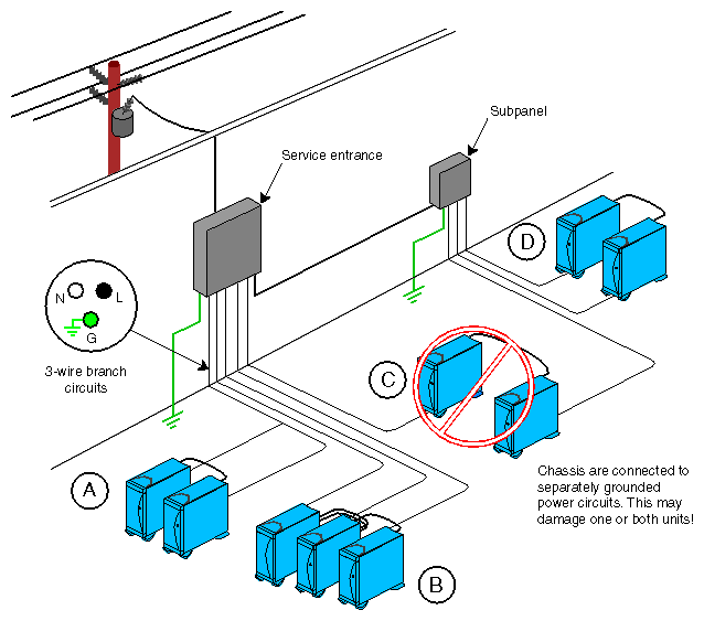
Proper electrical grounding is critical. All parts of the server must be on the same grounded power supply. Otherwise, the server's system board will be damaged. Components may be connected to different electrical circuits, but those circuits must originate at the same power supply (electrical service entrance or breaker box).
Figure 2-1 shows four possible power and grounding configurations for Origin200 and Origin200 GIGAchannel servers:
Configuration A is valid. Note that both modules are connected to the same branch circuit, and such a circuit would be required to supply 30 amp.
Configuration B is also valid. Although the server modules and GIGAchannel expansion chassis are each on separate branch circuits, all three circuits are grounded at a service entrance.
Configuration C is not valid. Each module is grounded in a different location, which could result in differences in ground potential and possible damage to the modules.
Configuration D is valid. The server modules and GIGAchannel expansion chassis are grounded at a subpanel.
The weight of the server can vary considerably, depending upon the option drives you install in your system and their types. Table Table 2-1 indicates the minimum and maximum weights of a single Origin200 module and GIGAchannel expansion chassis.
Table 2-1. Minimum and Maximum Weight of the Server
Component | Minimum Weight | Maximum Weight |
|---|---|---|
Origin200 server module | 40 lbs (18 kg) | 75 lbs (34 kg) |
GIGAchannel expansion chassis | 35 lbs (16 kg) | 65 lbs (29 kg) |
To estimate the minimum and maximum weight of your particular system, add the various weights of each component. For example, if you have a dual-module system, the minimum weight is 80 lbs (36 kg). If it is a dual-module Origin200 GIGAchannel system, the GIGAchannel chassis adds a minimum additional 35 lbs (16 kg).
The mounting shelf provided with a rackmount Origin200 and Origin200 GIGAchannel module can support the weight of a fully loaded chassis.
| Note: The rackmounting shelf does not isolate the server from mechanical shock and vibration. If you plan to use a rackmount Origin200 server in an environment that will subject the system to excess vibration, you should obtain a mounting system capable of dampening the vibration. See “Physical and Environmental Specifications” for information on mechanical shock and vibration. |
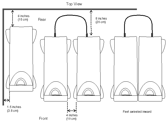
Be sure to provide adequate space for proper airflow and cooling. Refer to Table 1-7 in Chapter 1, “Overview of the Origin200 and Origin200 GIGAchannel Server” for a complete list of environmental specifications. Be aware that air flows from the front of the system to the rear. See “Air Flow, Fans, and Blower” for a description of the air flow through the Origin200 server.
Figure 2-2 shows the minimum distances required around the chassis.
Unpack the server and check the shipment to make sure you received all the necessary pieces.
The following sections describe the basic pieces included with each type of server. Read through them to familiarize yourself with the parts of your server and to be sure you received all the pieces required to set up the system.
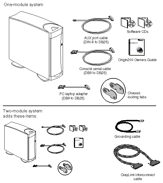
Table 2-2 lists the parts included with an Origin200 server in a tower configuration.
Table 2-2. Parts Included With an Origin200 Server, Tower Configuration
Part | Single-Module System | Two-Module System |
|---|---|---|
CPU module | 1 | 2 |
Console serial cable | 1 | 2 |
AUX port cable | 1 | 2 |
PC adapter cable | 1 | 2 |
Origin200 and Origin200 Giga | 1 | 2 |
Origin200 and Origin200 Giga | 1 | 2 |
Software CDs (including CDs of the version of IRIX pre-installed on your system disk) | Varies | Varies |
Chassis locking tabs | 1 pair | 2 pair |
Power cord (appropriate for your location) | 1 | 2 |
CrayLink interconnect cable | n/a | 1 |
Grounding cable | n/a | 1 |
Figure 2-3 shows the items packed with a basic Origin200 server in a tower configuration.
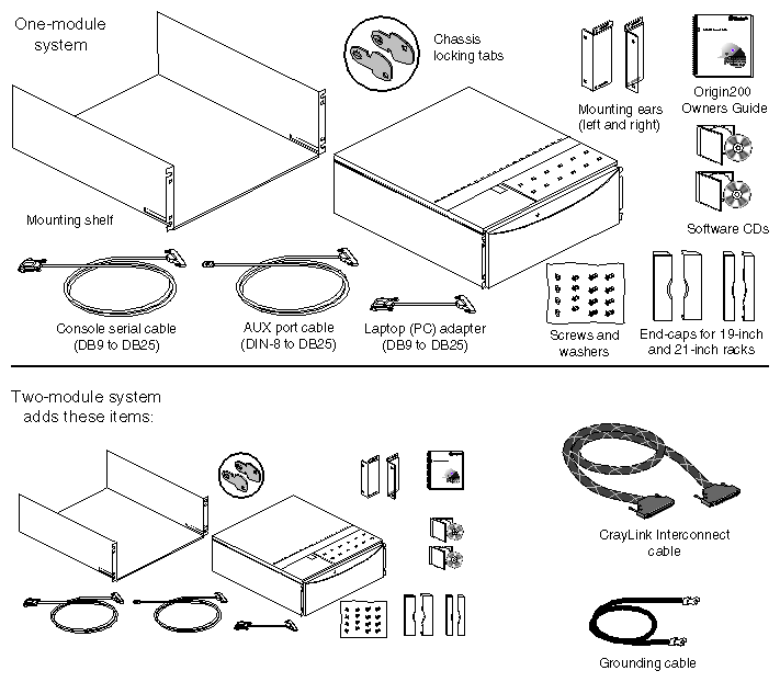
Table 2-3 lists the parts included with an Origin200 server in a rackmount configuration.
Table 2-3. Parts Included With an Origin200 Server, Rackmount Configuration
Part | Single-Module System | Two-Module System |
|---|---|---|
CPU module | 1 | 2 |
Console serial cable | 1 | 2 |
AUX port cable | 1 | 2 |
PC adapter cable | 1 | 2 |
Mounting shelf | 1 | 2 |
Mounting ears | 2 | 4 |
Cosmetic end caps for 19-inch racks | 2 | 4 |
Cosmetic end caps for 21-inch racks | 2 | 4 |
Origin200 and Origin200 Giga | 1 | 2 |
Origin200 and Origin200 Giga | 1 | 2 |
Software CDs (including CDs of the version of IRIX pre-installed on your system disk) | Varies | Varies |
Chassis locking tabs | 1 pair | 2 pair |
Power cord (appropriate for your location) | 1 | 2 |
CrayLink interconnect cable | n/a | 1 |
Grounding cable | n/a | 1 |
Figure 2-4 shows the various items shipped with an Origin200 server in a rackmountable configuration.
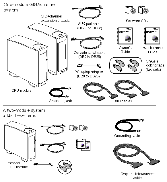
Table 2-4 lists the parts included with an Origin200 GIGAchannel server in a tower configuration:
Table 2-4. Parts Included With an Origin200 GIGAchannel Server, Tower Configuration
Part | Single-Module System | Two-Module System |
|---|---|---|
CPU module | 1 | 2 |
GIGAchannel expansion chassis | 1 | 1 |
Console serial cable | 1 | 2 |
AUX port cable | 1 | 2 |
PC adapter cable | 1 | 2 |
Origin200 and Origin200 Giga | 1 | 2 |
Origin200 and Origin200 Giga | 1 | 2 |
Software CDs (including CDs of the version of IRIX pre-installed on your system disk) | Varies | Varies |
Chassis locking tabs | 2 pair | 3 pair |
CrayLink interconnect cable | n/a | 1 |
XIO cables | 2 | 2 |
Grounding cable | 2 | 3 |
Power cord (appropriate for your location) | 2 | 3 |
Figure 2-5 shows these items.
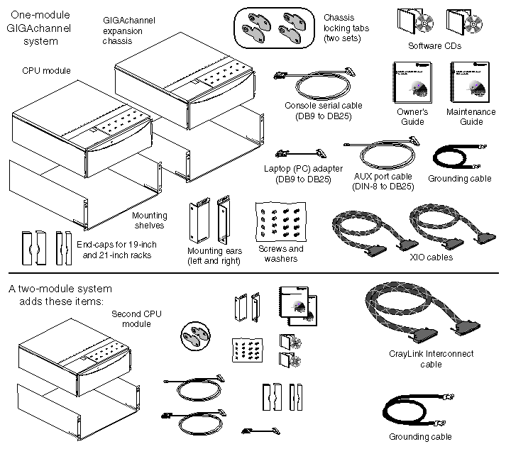
Table 2-5 lists the parts included with an Origin200 GIGAchannel server in a tower configuration:.
Table 2-5. Parts Included With an Origin200 GIGAchannel Server, Rackmount Configuration
Part | Single-Module System | Two-Module System |
|---|---|---|
CPU module | 1 | 2 |
GIGAchannel expansion chassis | 1 | 1 |
Console serial cable | 1 | 2 |
AUX port cable | 1 | 2 |
PC adapter cable | 1 | 2 |
Mounting shelf | 2 | 3 |
Mounting ears | 4 | 6 |
Cosmetic end caps for 19-inch racks | 4 | 6 |
Cosmetic end caps for 21-inch racks | 4 | 6 |
Origin200 and Origin200 Giga | 1 | 2 |
Origin200 and Origin200 Giga | 1 | 2 |
Software CDs (including CDs of the version of IRIX pre-installed on your system disk) | Varies | Varies |
Chassis locking tabs | 2 pair | 3 pair |
Power cord (appropriate for your location) | 2 | 3 |
CrayLink interconnect cable | n/a | 1 |
XIO cables | 2 | 2 |
Grounding cable | 2 | 3 |
Power cord (appropriate for your location) | 2 | 3 |
Figure 2-6 shows these items.
Depending upon which server you have (Origin200 or Origin200 GIGAchannel), how many CPU modules are in the server (one or two) and whether you have an optional Origin Vault disk expansion cabinet, there are several ways to configure your server. These are described in the following sections:
Each of these sections provides an overview of what is involved with setting up the server and describes any I/O performance issues.
In all cases, install drives after placing the server modules in their final locations. Drives add weight to the modules and make them more difficult to move.
To set up a single-module Origin200 server, follow these basic steps:
Install any PCI and memory options.
Install option drives (3.5 inch and 5.25 inch).
Connect external cables, such as the console serial cable, Ethernet, and power.
To set up a single-module Origin200 server with an Origin Vault disk expansion cabinet, follow these basic steps:
Install any PCI and memory options in the CPU module, including the PCI SCSI adapter option to which you connect the Origin Vault.
Install option drives (3.5 inch and 5.25 inch) in either the CPU module or the Origin Vault.
Connect external cables, such as the console serial cable, Ethernet, SCSI (to the Origin Vault), and power cables.
With a dual-module Origin200 server, you have a choice of which module will be the master and which will be the slave. In this case, follow these basic steps:
Configure one of the modules as the slave (all modules are shipped pre-configured as master modules).
Install any PCI and memory options.
Connect external cables, such as the console serial cable, networking, and power.
Install option drives (3.5 inch and 5.25 inch) in either of the two CPU modules.
Connect the two CPU modules together with CrayLink and grounding cables.
To set up a dual-module Origin200 server with an Origin Vault disk expansion cabinet, follow these basic steps:
Configure one of the modules as the slave (all modules are shipped pre-configured as master modules).
Install any PCI and memory options; choose which of the modules (master or slave) will attach to the Origin Vault and install the PCI SCSI option in that module.
Connect external cables, such as the console serial cable, networking, SCSI (to the Origin Vault), and power.
Install option drives (3.5 inch and 5.25 inch) in either of the two CPU modules or the Origin Vault.
Connect the two CPU modules with CrayLink and grounding cables.
You may observe better I/O performance if you balance your PCI options (including the SCSI adapter for the Origin Vault) between the two CPU modules. For example, if you have two FDDI boards, place one in each CPU module.
To set up a single-module Origin200 GIGAchannel server, follow these basic steps:
Install any memory options in the CPU module.
Install PCI options in either the CPU module or the GIGAchannel expansion cabinet. (You may see better performance installing the cards in the GIGAchannel cabinet.)
Install XIO options in the GIGAchannel cabinet.
Connect the CPU module to the GIGAchannel cabinet with two XIO cables and a grounding cable.
Install option drives (3.5 inch and 5.25 inch) in the CPU module.
Connect external cables, such as the console serial cable, networking, and power.
In terms of I/O performance, you may see better PCI performance if you install your PCI cards in the GIGAchannel expansion cabinet rather than in the CPU module.
To set up a single-module Origin200 GIGAchannel server with an Origin Vault, follow these basic steps:
Install any memory options in the CPU modules.
Install PCI options in either the CPU module or the GIGAchannel expansion cabinet; choose where you will install the PCI SCSI option for the Origin Vault, either in the CPU module or the GIGAchannel cabinet. You may see better performance if you install the PCI card in the GIGAchannel cabinet.
Install XIO options in the GIGAchannel cabinet.
Connect the CPU module to the GIGAchannel cabinet with two XIO cables and a grounding cable.
Install option drives (3.5 inch and 5.25 inch) in the CPU modules and the Origin Vault.
Connect external cables, such as the console serial cable, networking, SCSI (to the Origin Vault), and power.
In terms of I/O performance, you may see better PCI performance if you install your PCI cards in the GIGAchannel expansion cabinet rather than in the CPU module.
To set up a dual-module Origin200 GIGAchannel server, follow these basic steps:
Configure one of the CPU modules as the slave (all modules are shipped pre-configured as master modules).
Install PCI options in either of the CPU modules or the GIGAchannel expansion cabinet. You may see better I/O performance if you place the PCI cards in the GIGAchannel expansion cabinet.
Install XIO options in the GIGAchannel cabinet.
Connect one of the CPU modules to the GIGAchannel cabinet with two XIO cables and a grounding cable.
Connect external cables, such as the console serial cable, networking, and power.
Install option drives (3.5-inch and 5.25-inch) in either of the two CPU modules.
Connect the two CPU modules with CrayLink and grounding cables.
You can connect the GIGAchannel expansion cabinet to either a master or a slave module. There are no I/O performance advantages to either configuration.
You may observe better I/O performance if you first install PCI cards in the GIGAchannel expansion cabinet, then balance any remaining PCI cards between the master and slave CPU modules.
To set up a dual-module Origin200 GIGAchannel server with an Origin Vault, follow these basic steps:
Configure one of the CPU modules as the slave (all modules are shipped pre-configured as master modules).
Install PCI options in either of the CPU modules or the GIGAchannel expansion cabinet; choose where you will install the PCI SCSI option for the Origin Vault, either in one of the CPU modules or the GIGAchannel cabinet. You may see better I/O performance if you install PCI cards first in the GIGAchannel cabinet, then balance the remaining cards between the two CPU modules.
Install XIO options in the GIGAchannel cabinet.
Connect one of the CPU modules to the GIGAchannel cabinet with two XIO cables and a grounding cable.
Connect external cables, such as the console serial cable, networking, SCSI (for the Origin Vault), and power.
Install option drives (3.5-inch and 5.25-inch) in either of the two CPU modules or the Origin Vault.
Connect the two CPU modules together with CrayLink and grounding cables.
You can connect the GIGAchannel expansion cabinet to either a master or a slave module. There are no I/O performance advantages to either configuration.
You may observe better I/O performance if you place your PCI cards first in the GIGAchannel expansion cabinet, then balance any remaining PCI options between the CPU modules.
To set up a dual-module Origin200 GIGAchannel server with two GIGAchannel expansion cabinets, follow these basic steps:
Configure one of the CPU modules as the slave (all modules are shipped pre-configured as master modules).
Install PCI options in either of the CPU modules or the GIGAchannel expansion cabinets You may see better I/O performance if you install PCI cards first in the GIGAchannel cabinets, then balance any remaining cards between the two CPU modules.
Install XIO options in the GIGAchannel cabinets.
Connect one of the CPU modules to one of the GIGAchannel cabinets with two XIO cables and a grounding cable.
Connect the second GIGAchannel cabinet to the remaining CPU module.
Connect external cables, such as the console serial cable, networking, SCSI (for the Origin Vault), and power.
Install option drives (3.5-inch and 5.25-inch) in either of the two CPU modules.
Connect the two CPU modules together with CrayLink and grounding cables.
Each GIGAchannel expansion cabinet must be connected to its own CPU module. You cannot daisy-chain the expansion cabinets. Also, you may see better I/O performance if you install PCI cards first in the GIGAchannel cabinets, then balance any remaining PCI cards between the two CPU modules.
The following sections describe how to put together all the pieces of your server:
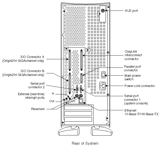
Figure 2-7 provides an overview of the various connectors that are available on a CPU module.
For complete descriptions of these connectors, see Chapter 1, “Overview of the Origin200 and Origin200 GIGAchannel Server” and Appendix A, “Connector Pinout Assignments.”
When working on an Origin200 server, follow these safety precautions:
Place the chassis on a surface capable of supporting a minimum of 40 lbs (about
18 kg) per module. Each fully configured Origin200 CPU module can weigh up to 75 lbs (34 kg).Before opening the chassis, turn off the master power switch at the rear of the system. This disconnects power to the power supply. The software-power switch at the front of the chassis shuts off the server, but does not disconnect the power supply.
When opening the chassis, for example to install and remove additional peripherals and memory, always observe proper electrostatic discharge (ESD) procedures. Make sure you are properly grounded with a wrist or heel strap before handling sensitive boards and drives. All SGI peripheral, memory, and upgrade options are shipped with wrist straps.
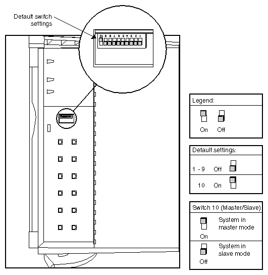
In a two-module Origin200 or Origin200 GIGAchannel server, one CPU module is said to be the master module and the other is said to be the slave module. This relationship is set by a DIP switch located on the module system controllers (MSC) of each chassis, and has the following features:
Only the master module can have a system console.
The master module controls the power-on and power-off sequence.
You can communicate with the module system controller (through the AUX port) in the master, but not in the slave module.
Both master and slave modules must have memory (DIMMs) installed in them.
The slave module does not require any disk drives.
In an Origin200 GIGAchannel server, either the master or the slave module can be connected to the GIGAchannel expansion cabinet.
Follow these steps to select one of your Origin200 modules as the slave:
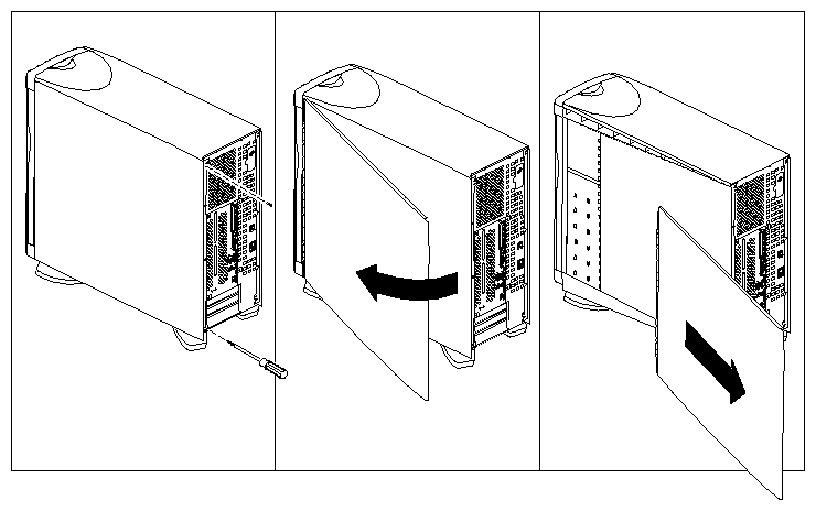
If the slave system is in a tower configuration, remove the side panel as shown in Figure 2-8.
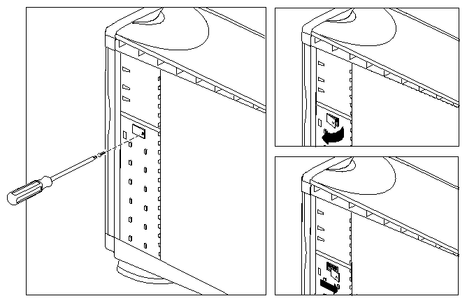
Remove the module system controller (MSC) access plate, as shown in Figure 2-9
Locate the MSC DIP switch, as shown in Figure 2-10.
Using a ballpoint pen or similar object, change switch 10 to “off” to place this module in slave mode. See Figure 2-10.
Replace the MSC access plate.
Tower systems only: If you have no further options to install inside the CPU module (such as memory and PCI option boards), replace the side panel. Otherwise, leave the side panel off and continue assembling the server.
Make sure you understand where you will install PCI options and, in the case of the Origin200 GIGAchannel server, where you will attach the GIGAchannel expansion cabinet. See “Planning the Server Configuration”.
If you have additional memory or PCI option boards that you wish to install do so now.
Turn to the Origin200 and Origin200 Giga Maintenance Guide for information on opening the modules, installing boards, and installing memory.
If you have an Origin Vault disk expansion cabinet, verify that the PCI SCSI option is installed. If it is installed, you should see a SCSI connector in one of the PCI slots at the rear of the system.
If you have an Origin200 GIGAchannel server, install any XIO boards in the GIGAchannel expansion cabinet. See the Origin200 and Origin200 GIGAchannel Maintenance Guide.
Do not install disk drives yet. These make the modules heavier and more difficult to move as you continue to set up the system.
If you are installing the system in an equipment rack, turn now to Chapter 3, “Installing an Origin200 System in a Rack.” Follow the instructions for installing the system in an equipment rack.
When you are finished installing the system in the equipment rack, continue with the installation process in this chapter.
If you are installing a tower (free-standing) server, place it in the location you determined earlier (see “Choosing a Location for the Server”).
If you are installing an Origin200 GIGAchannel server, follow these steps to attach the GIGAchannel expansion cabinet to a CPU module.
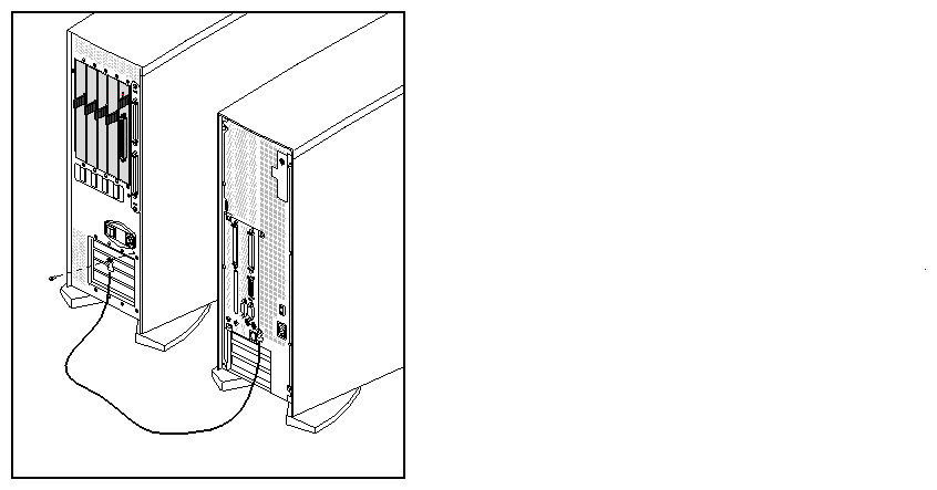
Attach the grounding cable between the GIGAchannel cabinet and the CPU module, as shown in Figure 2-11.
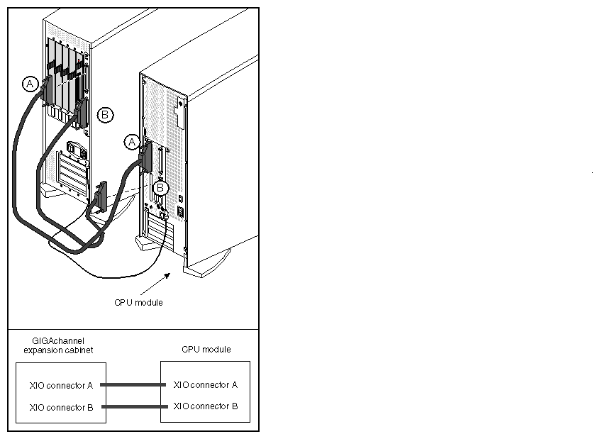
Attach the XIO cables between the GIGAchannel and the CPU module, as shown in Figure 2-12.
Attach a cable between XIO connector A on the GIGAchannel and connector A on the CPU module.
Attach the other cable between XIO connector B on the GIGAchannel and connector B on the CPU module.
If you have two GIGAchannel expansion cabinets, each one must be connected to a separate CPU module (one to the master module and one to the slave module). You cannot daisy chain GIGAchannel cabinets and you cannot connect the same cabinet to two different CPU modules.
| Note: An Origin200 GIGAchannel server cannot boot unless there is either a GIGAchannel cabinet attached correctly to the XIO connectors on the back of the server, or the XIO A and B connectors are connected together with a single XIO cable (loopback mode). See “Running an Origin200 GIGAchannel Without a GIGAchannel Expansion Cabinet (Loopback Mode)” for information about running an Origin200 GIGAchannel server without a GIGAchannel. |
After you have placed the server in the desired location (either in a free-standing, tower configuration or mounted in an equipment rack), install any option drives.
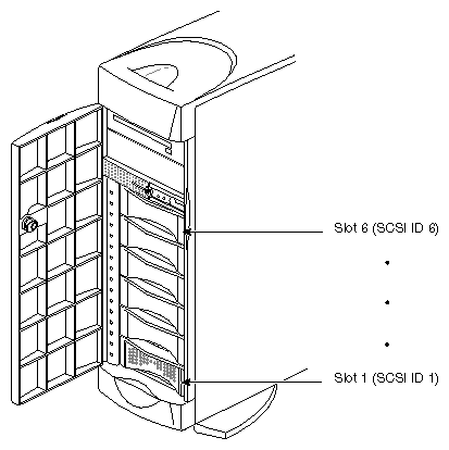
All 3.5-inch drives shipped from SGI for use in Origin200 systems are attached to mounting sleds. The SCSI ID of the drive is set automatically when it is installed in the system. The bottom 3.5-inch drive slot (rightmost slot in a rack system) is drive ID 1, and the top 3.5-inch drive slot (leftmost slot in a rack system) is drive ID 6. See Figure 2-13.
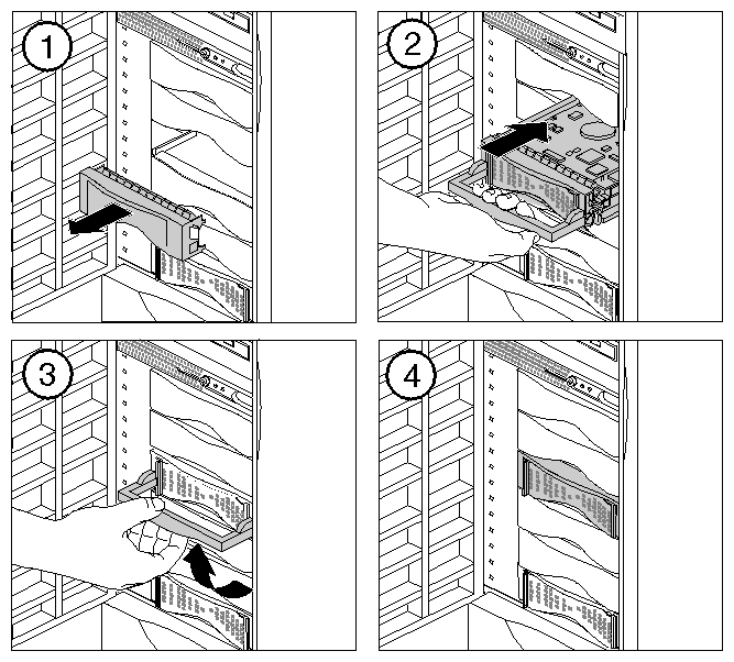
Install any 3.5-inch drives as shown in Figure 2-14.
Save any blanking plates you remove in case you remove the drives later. For more information about using 3.5-inch drives, see Chapter 6, “Installing and Configuring Peripherals.”
| Note: If you are installing a 5.25-inch drive that is not from SGI, see “Installing, Removing, and Configuring 5.25-Inch Peripherals”. |
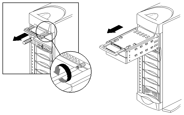
5.25-inch drives are installed in a removable carrier in the CPU module. Follow these step to remove the carrier:
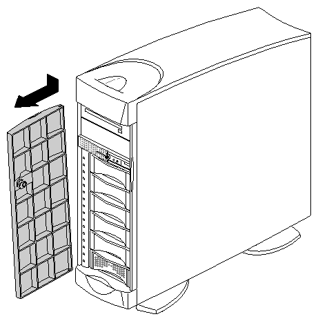
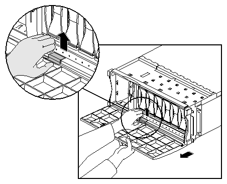
Remove the door of the CPU module.
Pull the door open.
If your system is in a tower configuration, push down on the top, outer edge of the door, as shown in Figure 2-15. The door pops off its hinges.
If the system is in a rackmount configuration, lift the door assist tab and pull the door off, as shown in Figure 2-16.
Remove the carrier, as shown in Figure 2-17.
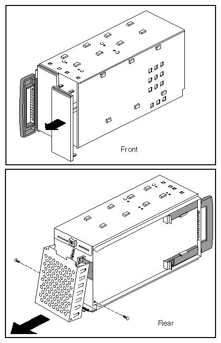
Install the 5.25-inch drive in the carrier. The carrier can hold one full-height drive or two half-height drives.
Remove one or two of the blanking plates from the front of the carrier, depending upon whether you are installing a half-height or a full-height drive.
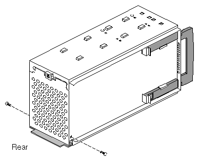
Using a #2 Phillips screwdriver, remove the screws that hold the access plate to the rear of the carrier, then remove the access plate. See Figure 2-18.
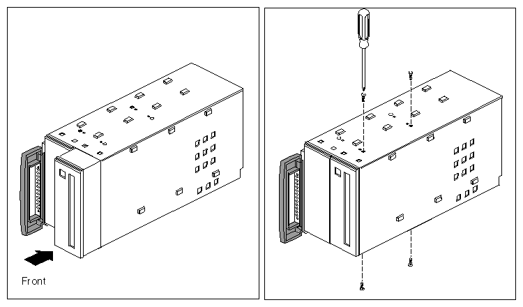
Slide the drive into the peripheral carrier and attach it with four screws through the side of the carrier, as shown in Figure 2-19.
When installing the drive, be careful to keep track of its orientation in the carrier so that you do not install the drive upside down.
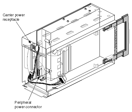
Attach one of the power connectors at the rear of the carrier to the drive. Use whichever connector fits conveniently for the position of the drive's power receptacle. See Figure 2-20.
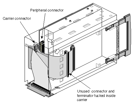
Attach one of the connectors on the SCSI cable to the drive. Use whichever connector fits conveniently for the position of the drive's SCSI connector. See Figure 2-21.
Tuck the unused connector and terminator inside the carrier.
Replace the access plate. See Figure 2-22. The plate should cover all of the loose wires (power and SCSI) at the rear of the carrier.

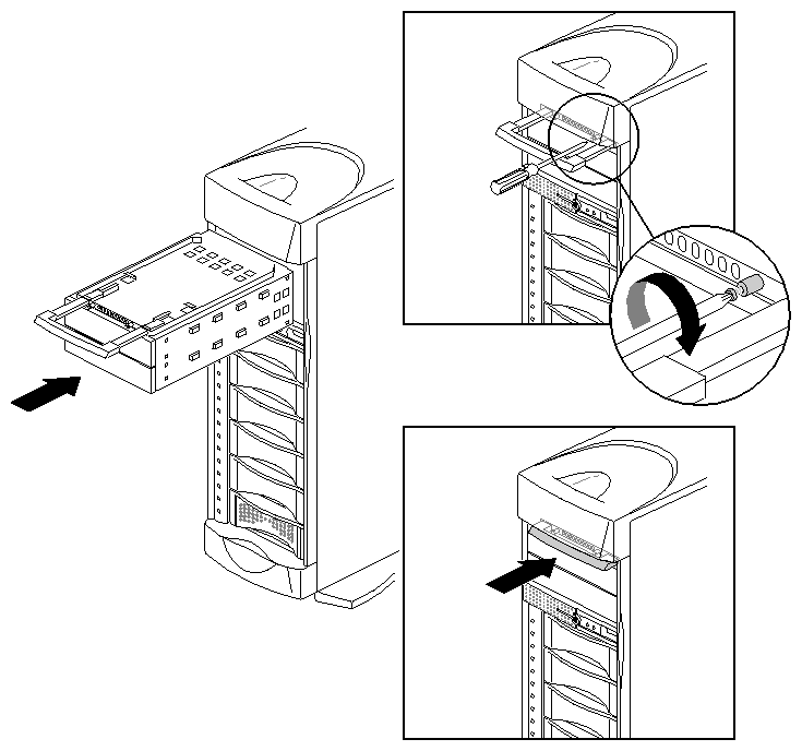
Note: Be sure to reinstall the access plate on the rear of the carrier. The plate protects the power and SCSI cables from damage when you slide the carrier into the system. Slide the carrier into the system, secure it with the captive screws, and push in the retractable handle. See Figure 2-23.
If you have an optional Origin Vault disk expansion cabinet, you may attach it to your server now. See the Origin Vault Owner's Guide, included with the option.
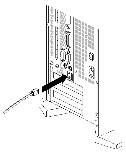
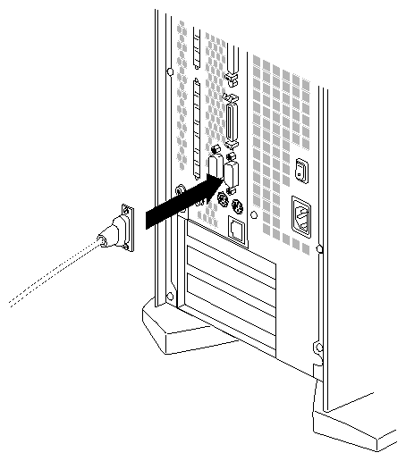
Connect the RS-232 serial cable (provided) to an ASCII terminal. The cable is approximately 10 feet (3 meters) long. Plug the D-shaped 9-pin connector into serial port 1 on the back of the system, as shown in Figure 2-25.
Connect the other end of the serial cable, which has a D-shaped 25-pin connector, to a serial (ASCII) terminal.
You can use a computer or a workstation as the system console instead of using an ASCII terminal. For more information, see “Using Another Computer or Workstation as the System Console” in Chapter 4.
Before connecting two CPU modules, you should already have configured one module as the slave. (See “Setting the Slave CPU Module (Two-Module Servers Only)”.)
| Note: You can connect two CPU modules only if they have the same speed processors. You cannot connect modules whose CPUs run at different clock speeds. |
Follow the steps in this section to connect the modules of a two-module Origin200 or Origin200 GIGAchannel server.
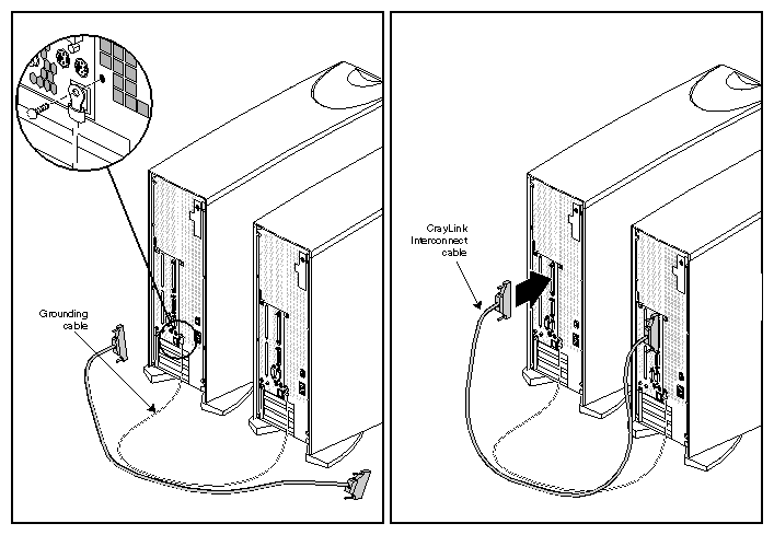
Connect the grounding cable and CrayLink cable between the two chassis, as shown in Figure 2-26.
You are finished connecting the modules.
If your Origin200 GIGAchannel server was shipped with XIO boards installed, take a moment to press on each of the board levers on the XIO boards. Occasionally during shipping and handling, one of the levers can be jostled loose. The server will still boot and run if one of the board levers is loose, but the XIO board may not be recognized and configured by the system.
Attach the power cables to all of the parts of server (CPU modules, GIGAchannel expansion cabinet, and optional Origin Vault).
When connecting power to the two modules, you may use different electrical circuits (circuits protected by individual fuses or breakers). However, both circuits must be connected to the same grounded power source (service entrance or breaker box). See Figure 2-1. You may also attach the different parts of the server to a power distribution unit (PDU) of sufficient amperage.
| Caution: You must connect the power cables to the same grounded power supply or the system will be damaged. |
You are ready to turn on the system.
Follow these steps to turn on the system:
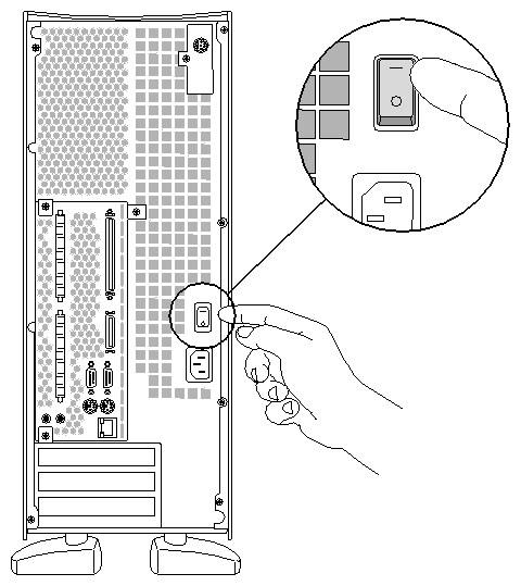
At the rear of the system, turn the master power switch on, as shown in Figure 2-27.
If you have more than one cabinet in your Origin200 server, turn them on in the following order: Origin Vault expansion cabinet, GIGAchannel expansion chassis, slave CPU module, and finally the master CPU module.
When you turn on the master power switch, the status LED on the front panel briefly flashes all three of its colors in sequence.

Note: If you have an Origin200 GIGAchannel server, be sure the XIO cables are properly connected before you turn on the master power switches on the CPU module and GIGAchannel expansion chassis. If you turn on the master power switches without the XIO cables properly connected, the hardware may not function correctly. Wait a few moments for the server to start. You should see some messages boot-up displayed on the system console.
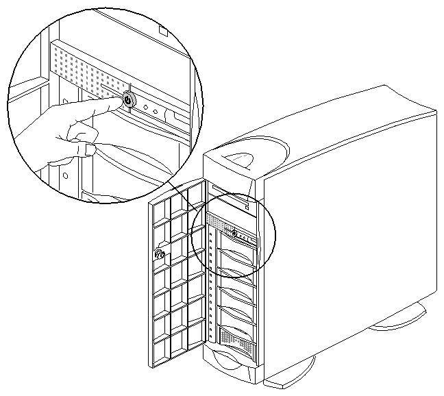
If you do not see any messages after turning on the main power switch, press the front of the CPU module (the master in a two-module server), press the front power switch, as shown in Figure 2-28.
In a two-module system, press the front power switch on the master module.
Press the button far enough to feel a slight “click.”
After you press the button, the status LED blinks green, then turns solid green as the system boots.
As the system boots, power is applied to the 3.5-inch drives in order, starting with the drive in slot 1 (the system disk) of the master CPU module and proceeding to slot 6. After the 3.5-inch drives have power, power is applied to the 5.25-inch drives. This same process is repeated for the slave CPU module in a two-module system.
If you have an Origin Vault attached to the server, the disks in the Origin Vault spin up in the same relative order as in the CPU module.
When you log into the system for the first time, perform the following tasks:
Assign an internet protocol (IP) address to the system (so that it can communicate on the network).
Optional: Assign passwords to critical system accounts (such as root and httpd).
Optional: Allow or deny access to network services available on your Origin200 server (such as finger, ftp, telnet, and so forth).
You can perform these basic tasks from the system console (for example, an ASCII terminal) that you attached to serial port 1. Once the server is available on the network, you can access various system administration features from other computers and workstations on your network using a World Wide Web browser.
After the system boots, you see the following prompt on the console:
IRIS login: |
Follow these steps:
This command starts the Internet Gateway setup program, which allows you to configure the system for network access. You see a series of screens with various prompts and information. Make whatever changes you wish to your system configuration.
Part of the process of making those changes includes rebooting the system. After the system has rebooted, you can modify your system's configuration over the network using a World Wide Web browser. See “Accessing Your Server Over the Web” in Chapter 4.
