This chapter describes the functions of system controllers, in these sections:
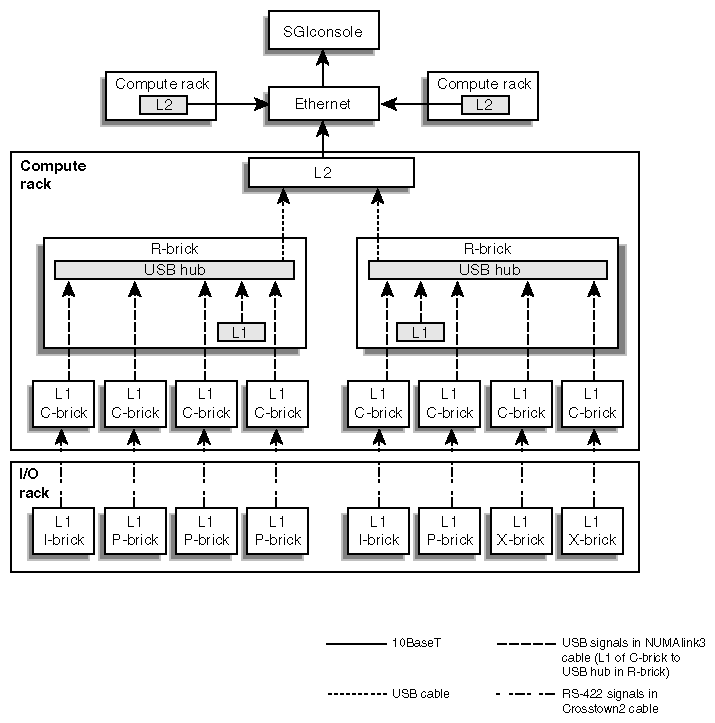
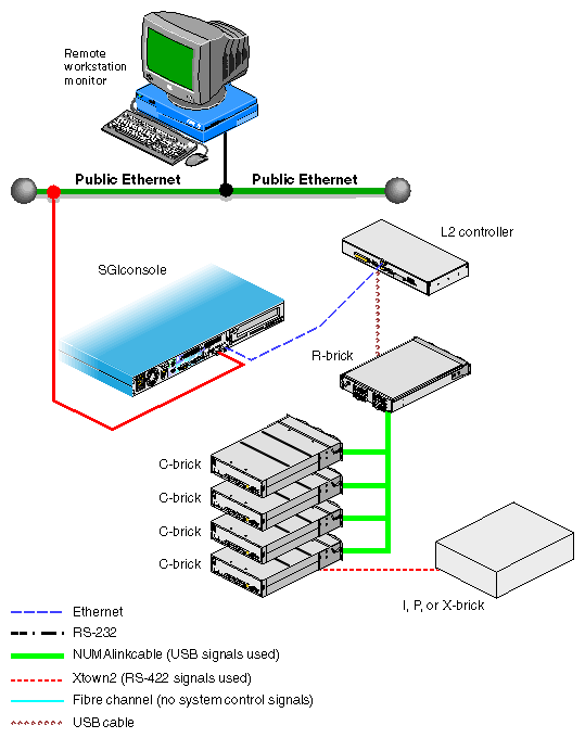
The control systems for the SGI Origin 3000 series servers manage power control and sequencing, provide environmental control and monitoring, initiate system resets, store identification and configuration information, and provide console/diagnostic and scan interface. The SGI Origin 3000 series server has two levels of control:
L1: brick-level system controller. The L1 system controller is designed into all bricks except the D–brick; controller function varies slightly by brick.
L2: rack-level system controller (optional in the SGI Origin 3200 server system). This controller is standard in each tall rack containing C–bricks. The L2 allows remote maintenance, controls resource sharing, controls the L1 controllers in the system, and maintains controller configuration and topology information between itself and other L2 controllers.
In an SGI Origin 3200 server with no L2 controller, the L1 controllers on the C–bricks work as peers in the server system. In all SGI Origin series servers with L2 controllers, the L1 controllers are slave devices to the L2 controller. The controllers communicate with each other in the following ways.
In the SGI Origin 3200 server with two C–bricks, the L1 controller of a C–brick communicates with the L1 controller of the other C–brick (not shown in Figure 3-1).
In any SGI Origin 3000 series server, an L1 controller of an I/O brick communicates with an L1 controller of a C–brick.
In the SGI Origin 3000 series server with L2 controllers, an L1 controller of a C–brick that is connected to an R–brick communicates with the L2 controller via the R–brick. If the server does not have an R–brick, such as the SGI Origin 3200 with an optional L2 controller, the C–brick connects to the L2 controller via the C–brick L1 port (USB port).
In the SGI Origin 3000 series server with multiple L2 controllers, they and a system console (like the SGIconsole) can connect with each other via an Ethernet hub, as shown in Figure 3-1, and via an Ethernet network.

Note: The D–brick, which is not monitored by the L2 controller, has its own ESI/ops panel module with a microcontroller for monitoring and controlling all elements of the D–brick. See “Enclosure System Interface/Operator (ESI/Ops) Panel Module” in Chapter 8 for details.
Figure 3-1 diagrams some of the interactions between the L1 and L2 controllers.
All bricks except D–bricks have L1 controllers. This section describes basic features of all L1 controllers:
The L1 controller performs many functions; many of the functions are common for the C–brick, R–brick, I–brick, P–brick, and X–bricks and some are specific to a brick type. Table 3-1 summarizes some of the functions that the L1 controller performs.
Table 3-1. L1 Controller Functions
Function | C–brick | R–brick | I–brick | P–brick | X–brick |
|---|---|---|---|---|---|
Controls voltage regulator modules (VRMs). | X | X | X | X | X |
Monitors voltage and reports failures. | X | X | X | X | X |
Controls voltage margining within the brick. | X | X | X | X | X |
Controls and monitors fan speed. | X |
| X | X | X |
Monitors and reports operating temperature and status of 48 VDC input power. | X | X | X | X | X |
Monitors and controls LEDs. | X | X | X | X | X |
Reads system identification (ID) PROMs. | X | X | X | X | X |
Monitors the power On/Off switch. | X | X | X | X | X |
Monitors the reset switch, and the nonmaskable interrupt (NMI) switch. | X |
|
|
|
|
Provides a USB hub chip that has six master ports: one port connects internally to the R–brick's L1 controller, four ports connect to the L1 controllers of four C–bricks (via the NUMAlink3 cable), and a master port connects to the L2 controller. |
| X |
|
|
|
Reports the population of the PCI cards and the power levels of the PCI slots. |
|
| X | X |
|
Powers on the PCI slots and their associated LEDs. |
|
| X | X |
|
Reports the power levels of the XIO slots. |
|
|
|
| X |
Controls the termination voltage margins of the XIO cards. |
|
|
|
| X |
Figure 3-2 shows the L1 controller front panel.
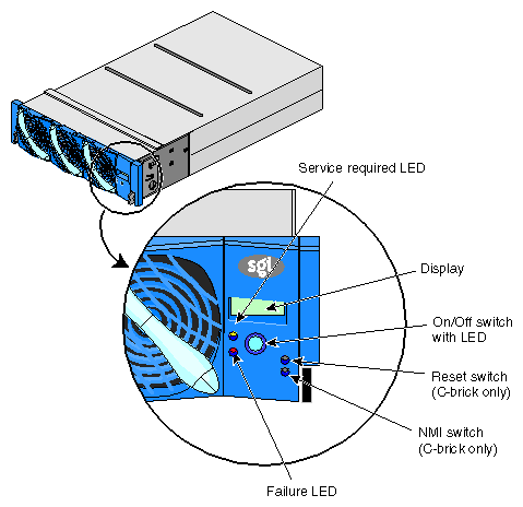
The front panel display contains the following items:
2 x 12 character liquid crystal display (LCD). The display uniquely identifies the brick, shows system status, warns of required service, and identifies a failed component.
On/Off switch with LED (button with light-emitting diode [LED]).
Service required LED.
Failure LED.
Reset switch and non-maskable interrupt (NMI) button switch (only on C–bricks).
Note: The reset and NMI switches are not available in the front panel of an I–brick, P–brick, X–brick, or R–brick.
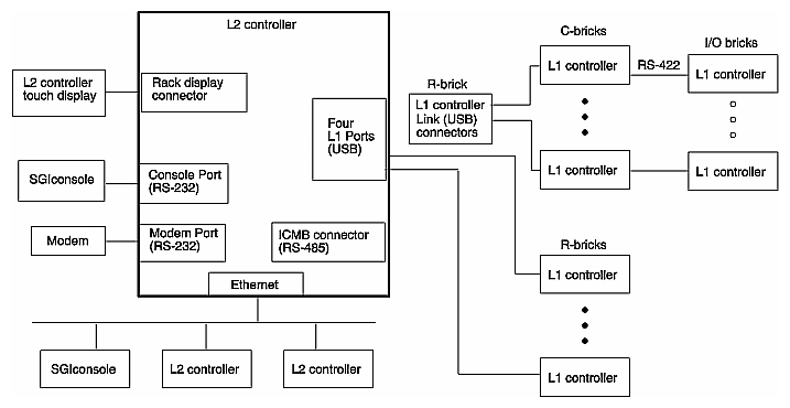
The L2 controller is a rack-level controller located at the top of the rack; it is a single-board computer that runs an embedded operating system out of flash memory.
The L2 system controller is optional in SGI Origin 3200 server systems, but is standard on all SGI Origin 3400 and SGI Origin 3800 server systems. The L2 system controller is required in a system in the following circumstances:
If the system contains an R–brick (Each SGI Origin 3400 and SGI Origin 3800 server system has an R–brick).
If remote maintenance of the system is required (any SGI Origin 3000 series server system).
The L2 controller is present in all the server tall racks that contain C–bricks, and all tall racks that have an L2 controller have an L2 controller touch display.
The L2 controller performs the following functions:
Controls resource sharing.
Controls all L1 controllers.
Maintains controller configuration and topology information between the L1 and L2 controllers.
Routes data between upstream devices and downstream devices.
Upstream devices (for example, rack display, console, and modem) provide control for the system, initiate commands for the downstream devices, and act on the messages that they receive from downstream devices.
Downstream devices (for example, the USB hub of the R–brick, and L1 controllers of the bricks) perform the actions that are specified by the L2 controller commands, send responses to the L2 controller that indicate the status of the commands, and send error messages to the L2 controller.
Allows remote maintenance via a modem.
In a system with more than one L2 controller, all L2 controllers are peers and each propagates configuration information to the other L2 controllers. Each L2 controller monitors its associated L1 controllers and propagates this information to the other L2 controllers.
Figure 3-3 diagrams the L2 controller and its interactions.
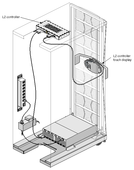
The L2 controller is mounted in the top of the tall or short rack (optional for short rack); it does not use configurable rack space. Figure 3-4 shows its location in a tall rack.
The L2 controller consists of touch display controllers, ports, and a software component, which are described in these subsections:
The L2 controller touch display is a 320 x 240 touch-pad LCD (liquid crystal display) screen display. The L2 controller's touch-screen translates what the user touches into commands and displays the results of the commands.
The L2 controller touch display is located on the front door of the cabinet, as shown in Figure 3-5.
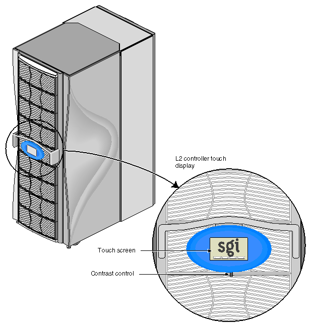
Figure 3-6 shows the ports on the L2 controller.
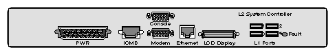
Table 3-2 summarizes the ports of the L2 controller.
Table 3-2. L2 Controller Ports
Quantity | Port | Connector Label | Connects To | Purpose or Notes |
|---|---|---|---|---|
4 | Standard downstream USB | USB hubs of R–bricks | In a system with no R–brick, this port connects to an L1 controller of a C–brick. The USB hub transfers status and control information between the L2 controller, which is the master of the USB ports, and the L1 controllers in the attached R–brick or C–bricks. | |
1 | Enet | Ethernet hub | This port provides a means to connect multiple L2 controllers and to connect multiple L2 controllers to a console like the SGIconsole. The Ethernet hub provides eight Ethernet connectors. Any of these eight connectors can be used to cascade to another hub. See Figure 3-7 . | |
1 | Console | Dumb terminal | Console and modem ports allow the user to input text-based commands and to receive text-based results. The console and modem ports operate in one of the following modes: | |
1 |
| Modem | Modem | L2 mode: L2 controller forwards all commands to the specified L2 controller. L1 mode: L2 controller forwards all commands to the specified L1 controller, except commands that are prefixed with CTRL T; the L2 controller interprets these commands. Console mode: L2 controller forwards all commands to the system console, except commands prefixed with CTRL T; the L2 controller interprets these commands. |
1 | LCD display | L2 controller touch display | This port is used to display status and error messages generated by the L1 or L2 controller on the display panel located in the front door of your system. | |
1 | PWR | Power bay | This port provides a power source to the L2 controller. |
The L2 controller connects to a modem through the modem connector on the back of the L2 controller. This connection provides a means of connecting remote support hardware to the system; however, the use of an Ethernet hub is the preferred method of connecting remote support hardware to the system.
The Ethernet hub provides eight Ethernet connectors. Figure 3-7 shows sample connections between the Ethernet hub, L2 controllers, and an SGIconsole.
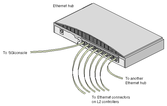
If a system has more L2 controllers than the Ethernet hub can accommodate, the Ethernet hub can be cascaded to a second Ethernet hub. The primary and secondary Ethernet hubs are connected by connecting the leftmost connector of the second Ethernet hub to any open connector on the primary hub. The Uplink button located next to the leftmost connector of the secondary Ethernet hub must be set to Uplink (the button is pushed in).
Large systems may require three Ethernet hubs in order to connect an SGIconsole to all of the L2 controllers in the system.
The choice of console type and the method of connecting the console to the SGI Origin 3000 series server depend on whether or not the server has an L2 controller.
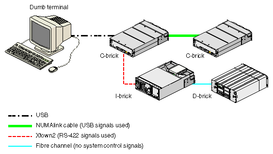
If you have an SGI Origin 3200 server without an L2 controller, you connect a dumb terminal to the C–brick (console port) as shown in Figure 3-8. This connection enables you to view the status and error messages generated by the L1 controller and to enter L1 commands to manage and monitor your system.
If you have an SGI Origin 3000 series server that has an L2 controller such as the SGI Origin 3400 server shown in Figure 3-9, you can either connect an SGIconsole to the L2 controller (the Ethernet port) or connect a dumb terminal to the L2 controller console port. If you have multiple L2 controllers, you can interconnect the SGIconsole and the various L2 controllers with an Ethernet hub.
These console connections to the L2 controller enable you to view the status and error messages generated by the L1 controllers on your server rack. You can also use these consoles to input L1 and L2 commands to manage and monitor your system.
For more details on connecting a console to your SGI Origin 3000 series server, see “Connecting a Console to Your Server System” in Chapter 2. For more information on monitoring your server, see “Monitoring Your Server” in Chapter 2.
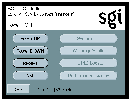
The L2 controller touch display provides a simple graphical interface that allows you to perform basic functions.
Figure 3-10 illustrates the L2 controller touch display.
The home window of the L2 controller touch display, shown in Figure 3-11, includes five buttons:
| Power UP | Power on selected bricks. | |
| Power DOWN | Power off selected bricks. | |
| RESET | Reset the system. | |
| NMI | Send non-maskable interrupts (NMIs) to the system. | |
| DEST | Select the bricks that will receive the function, such as power on or off. |
The top of the home window also includes the following information (with sample output):
Rack number (L2-004 in our example) of the L2 controller to which the L2 controller touch display is connected.
L2 controller system serial number (L7654321 in our example).
Server system name in parenthesis (firestorm in our example).
Power status (Power: OFF) for the bricks designated in the destination (DEST) field, which indicates all slots in all racks (r * s * [56 bricks] in our example).
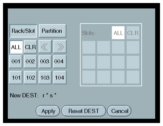
If you select the DEST button in the home window, the destination selection window, shown in Figure 3-12, appears. This window provides the following options:
| Rack/Slot | Select this option to select all slots (bricks) in all racks, all slots in multiple racks, or individual slots in a single rack. (You cannot select individual slots for multiple racks.) | |
| Partition | Select this option to select all the bricks in all partitions, or all bricks in individual or multiple partitions. | |
| ALL | If you select Rack/Slot, you can select all slots for all racks by selecting ALL on the left side of the window. If Partition is selected, you can select all bricks in all partitions by selecting ALL on the left side of the window. If you select ALL on the right side of the window, you select all slots for a particular rack. | |
| CLR | If you select CLR on the left side of the window, you clear the system of all rack or partition destination selections. If you select CLR on the right side of the window, you clear the system of all slot destination selections. | |
| Numbered selections | Select numbers on the left side of the window to select racks or partitions by number. Select numbers on the right side of the window to select slots by the number for a single rack. | |
| New DEST | This field displays the new destinations as you select them. | |
| Apply | If you select Apply, your destination selections are confirmed and the home window appears. The home window shows your destination selections in the DEST field. | |
| Reset DEST | Select this option to reset the destination to its previous setting. | |
| Cancel | Select this option to cancel the selected destinations and return to the home window. |
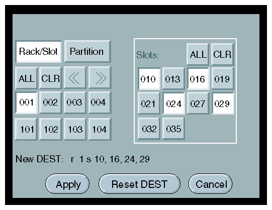
If you select Rack/Slot and a rack number (001 in our example) from the destination selection window, the Slots selection section appears as shown in Figure 3-13. This section provides the following options:
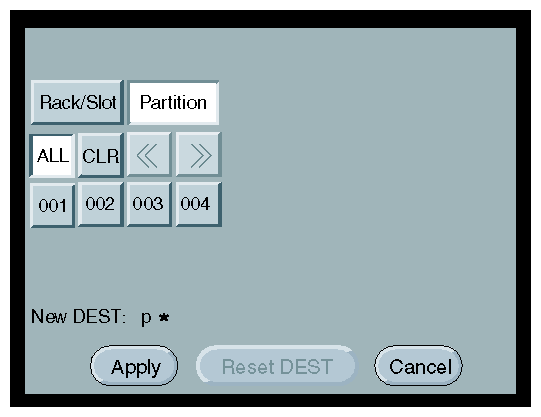
If you select Partition and ALL (to select all partitions in a server system) from the destination selection window, the partition selection window appears as shown in Figure 3-14.
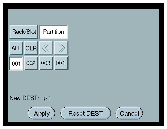
If you select Partition and a particular partition (001 in our example), the partition selection window appears as shown in Figure 3-15.
After you have determined the destination of the bricks that will receive the command that you select and you have selected the command from the home window, a command confirmation window appears. (For example, if you select Power UP from the home window, the Power UP command confirmation window, shown in Figure 3-16, appears.)
The command confirmation window displays a message that prompts you to select the OK button to issue the command to the destination (r * s * means all slots in all racks, in the example).
To initiate the command, select the OK button. To terminate the command, select the Cancel button. The window stays visible until the command successfully completes. (An unsuccessful command results from an L1/L2 error in processing the command or a time-out in waiting for a response.)
A similar confirmation window with a similar prompt and button selections appears for the Power UP, Power DOWN (Figure 3-17), Reset (Figure 3-18), and NMI (Figure 3-19) commands.
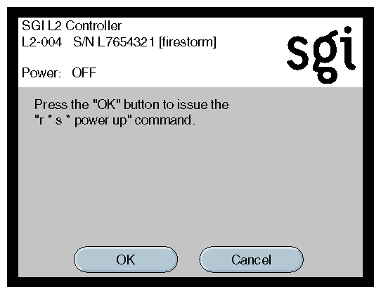
Figure 3-17 shows the Power DOWN command confirmation window.

Figure 3-18 shows the Reset command confirmation window.
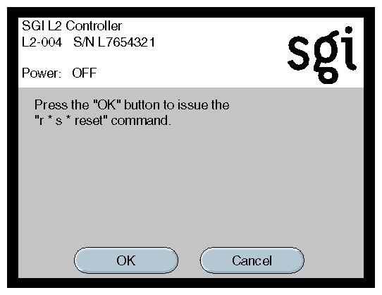
Figure 3-19 shows the NMI command confirmation window.

The L2 controller hardware includes L2 controller firmware. In order to access the L2 controller firmware, you must connect a console such as the SGIconsole or a dumb terminal to the L2 controller. For instructions to connect a console to the L2 controller, see “Connecting a Console to Your Server System” in Chapter 2.
The L2 firmware is always running as long as power is supplied to the L2 controller. If you connect a system console to the L2 controller's console port, the L2 prompt appears.
The L2 firmware operates in one of three modes:
L2 mode. The L2 prompt is visible and all input is directed to the L2 command processor.
Console mode from L2. Output from the system is visible and all input is directed to the system.
L1 mode from L2. The prompt from a single L1 is visible, and all input is directed to that L1 command processor.
After connecting to the L2 controller, the following prompt appears indicating that the L2 is ready to accept commands:
L2> |
Common operations are discussed in the following sections:
You can use the L2 config command to view the current system configuration from a brick level, as follows:
L2> config 127.0.0.1: 127.0.0.1:0:0 - 003c01 127.0.0.1:0:1 - 004c01 127.0.0.1:0:2 - 002c01 127.0.0.1:0:3 - 001x01 L2> |
As shown above, config produces a list of bricks in the system and the system controller address of each brick. This is similar to the output from using the config command on the L1 with the addition of the L2 IP address and USB port number. The structure of the brick's address is as follows:
a.b.c.d:x:y - rrrtss.p |
where:
| a.b.c.d | is the IP address of the L2. (In the example above, the IP address is 127.0.0.1.) | |
| x | is the USB port number. (In the example above, the port number is zero.) | |
| y | is the L1 index, as follows: 0 - local brick (the brick to which the USB cable is attached) 1 - I/O brick attached to the local brick 3 - C–brick attached to the local brick 4 - I/O brick (attached to the C–brick) that is attached to the local brick | |
| rrr | rack number | |
| t | type of brick (C–brick, I–brick, and so on) | |
| ss | slot number | |
| p | is the partition (not present if the system is not partitioned). |
A brick is identified by its rack and slot. In the example shown above, 003c01 is a C–brick in rack 3 and unit position 1.
If a command is not understood by the L2 system controller, in general it is passed on to the L1 system controllers. The destination determines which L1s receive the command. A destination, specified by the following, is a range of racks and slots:
rack <rack list> slot <slot list> |
The <rack list> specifies a list of racks. This can be a list delimited by commas, such that 2,4,7 specifies racks 2, 4, and 7. You can use a dash to specify a range of racks, such that 2-4 specifies racks 2, 3, and 4. Both nomenclatures can be combined, such that 2-4,7 specifies racks 2, 3, 4, and 7.
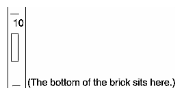
You can specify the <slot list> using the same nomenclature. The slot number, sometimes referred to as a bay number, is the unit position number located on the rack, slightly above where the bottom of the brick sits. Each rack unit position number is located toward the top of the two lines that mark the unit position that the number represents. For example, the rack numbering for a brick located in slot 10 would appear on the left front side of the rack, as shown in Figure 3-20:
The slot <slot list> is optional; if not given, then all slots in the specified rack(s) are implied. You should avoid specifying a rack list and a slot list that includes multiple racks and slots, such as rack 2-4,7 slot 1-8,11,13. Generally, a rack and slot together are used to specify an individual brick.
You can use the aliases r and s to specify rack and slot, respectively. You can use the alias all or * in both the <rack list> and the <slot list>, or by themselves, to specify all racks and all slots.
To send a command to all bricks in a partition, type the following:
partition <partition> <cmd> |
Default Destination
When the L2 starts, the default destination is set to all racks and all slots. You can determine the default destination by using the destination command, as follows:
L2> destination all racks, all slots L2> |
The following command sets the destinations to rack 2 and 3, all slots:
L2> r 2,3 destination 2 default destination(s) set L2> |
The following example shows what bricks are found in the default destination. If you type a command not understood by the L2, the command would be sent to these bricks.
| Note: In the current implementation, adding a brick to either rack 2 or 3 would not automatically include it in the default destination. You would need to reset the default destination. |
L2> destination 002c01 (127.0.0.1:0:2) 003c01 (127.0.0.1:0:0) L2> |
The following command resets the default destination to all racks and all slots:
L2> destination reset default destination reset to all racks and slots L2> |
Current Destination
The current destination is a range of racks and slots for a given command. For example, the following command sends the command <L1 command> to all bricks in racks 2, 3, 4, and 7:
L2> r 2-4,7 <L1 command> |
This is a one-time destination.
Command Interpretation
Some L2 commands are the same as the L1 commands. In many cases, this is intentional because the L2 provides sequencing that is necessary for a command to function correctly.
When L1 and L2 commands are similar, you can assure that an L1 command is entered for the bricks in the current destination by preceding the <L1 command> with the L1 command (this is a one-time destination):
L2> r 2-4,7 l1 <L1 command> |
See “L2 Controller Command Set” in Appendix B for details on the L2 commands.
All information, warnings, and error messages generated by any of the system controllers are in the following form:
002c01 ERROR: invalid arguments for `ver' command, try “help ver” |
The general format includes a brick identification and the type of message, followed by the message. A message may be the result of an invalid command, as shown in the example, or the result of tasks running on the L1, such as the environmental monitor.
Each L1 has a log of local events. Use the L1 command log to view events on any of the L1s.
The system can be powered on and off with the power command. This command is interpreted by the L2, because the bricks must be powered on in a specific order.
L2> power up L2> |
The power command may require several seconds to several minutes to complete. In the example above, all racks and slots in the default destination are affected. Any errors or warnings are reported as described in “Viewing Information, Warnings, and Error Messages”.
To power on or power off a specific brick, specify a current destination:
L2> r 2 s 5 power up L2> |
You can enter the power down and reset commands in a similar way. See Appendix B, “System Controller Commands” for details on the L2 commands.
L2> partition <partition number> <power up or power down>
In console mode, all output from the system is visible and all input is directed to the system.
To enter console mode from L2, press Ctrl+D at the L2 prompt and observe the response:
L2> Ctrl+D entering console mode 002c01 console, <CTRL_T> to escape to L2 . <system output appears here> . |
To return to L2 mode from console mode, press Ctrl+T:
Ctrl+T escaping to L2 system controller L2> |
At this point, you can enter any L2 or L1 command. When the command completes, the L2 returns to console mode:
Re-entering console mode 002c01 console, <CTRL_T> to escape to L2 |
To permanently engage the L2 mode, press Ctrl+T and then type the l2 command:
Ctrl+T escaping to L2 system controller L2> l2 L2 command processor engaged, <CTRL_D> for console mode. L2> |
When in console mode, the L2 can communicate with a brick set with the select command to be the system console or global master that receives the console input. This system console can be set and viewed with the select command.
The L2 chooses the C–brick as the default console in the following order of priority:
C–brick in the lowest numbered rack and slot, which has produced console output, and has an attached I–brick.
C–brick in the lowest numbered rack and slot, which has an attached I–brick.
C–brick in the lowest numbered rack and slot.
The select command by itself shows the current console mode settings:
L2> select console input: 002c01 console console output: not filtered console detection: L2 detected |
There are five common subchannels associated with console communications:
Subchannel a or 0 specifies CPU A.
Subchannel b or 1 specifies CPU B.
Subchannel c or 2 specifies CPU C.
Subchannel d or 3 specifies CPU D.
The console subchannel.
The output console input: 002c01 console shows that the L2 will send console input to brick 002c01 and the console subchannel will be used.
To change the brick that will be the system console, use the select <rack>.<slot> command, where <rack> is the rack and <slot> is the slot where the brick is located, as follows:
L2> select 3.1 console input: 003c01 console console output: no filtered console detection: L2 detected |
To change the subchannel used by the brick to be the system console, use select subchannel <a|b|c|d> command. (Use select subchannel console to select the console as the subchannel of the brick to be the system console.) For example, to select subchannel b, type the following:
L2> select subchannel b console input: 003c01 console CPU console output: no filtered console detection: L2 detected |
During the boot process on a multibrick system, there is a window of time during which the C–bricks are all producing output. This can result in a somewhat jumbled output at the L2. Console output can be filtered, though, which means that the L2 will show output only from the brick chosen to receive console input. You can turn on filtering with select filter on and turn it off with select filter off.
If you try to communicate with a brick chosen to receive console input, but the brick is not responding, a time-out condition results, as follows:
L2> Ctrl+D entering console mode 003c01 CPU2, <CTRL_T> to escape to L2 no response from 003c01 bedrock CPU2 system not responding no response from 003c01 bedrock CPU2 system not responding |
When this time-out condition occurs, either the brick is hung or the subchannel is not correct.
In L1 mode, the prompt from a single L1 is visible, and all input is directed to that L1 command processor.
To enter L1 mode, type the l1 command and specify a rack and a slot:
L2> r 2 s 1 l1 enterling L1 mode 002c01, <CTRL-T> to escape to L2 002c01-L1> |
To return to L2 mode, press Ctrl+T:
002c01-L1> Ctrl+T escaping to L2 system controller, <CTRL-T> to send escape to L1 L2> |
At this point, any L2 command can be entered. When the command completes execution, the L2 returns to L1 mode:
002c01-L1> |
To permanently engage the L2 mode, press Ctrl+T and type the l2 command:
002c01-L1> Ctrl+T escaping to L2 system controller, <CTRL-T> to send escape to L1 L2> l2 L2 command processor engaged, <CTRL-T> for console mode. L2> |
| Note: If you press Ctrl+D while in L1 mode, the L1 goes into console mode. Output from the system console will not be visible because the L2 never shows system console output unless the L2 is in console mode. To return to the L1 prompt at this point, press Ctrl+T twice, followed by the L1 command, to lock the L1 back into L1 mode. |
003c01> Ctrl+D entering console mode 002c01 console, <CTRL-T> to escape to L1 Ctrl+T escaping to L2 system controller, <CTRL-T> to send escape to L1 L2> Ctrl+T escaping to L1 system controller 003c01-L1> l1 L1 command processor engaged, <CTRL-T> to exit. 003c01-L1> |
The L1 operates in one of two modes:
| L1 Mode |
| |
| The L1 prompt is visible and all input is directed to the L1 command processor. |
| Console Mode from L1 |
| |
| Output from the system is visible and all input is directed to the system. |
| Note: Console mode from the L1 mode is not supported if the system contains an L2 controller. |
When you see a prompt of the following form, the L1 is ready to accept commands.
001c19-L1> |
Common operations include the following and are discussed in the sections that follow:
An L1 has limited knowledge of the system configuration. A C–brick only has information about its attached I/O brick and, if another C–brick is attached to it, information about that C–brick and its attached I/O brick. An I/O brick only has information about its attached C–brick. An R–brick only has information about itself.
You can view a brick's configuration information with the config command:
003c01-L1> config :0 - 003c01 :1 - 004i01 :2 - 002c01 :3 - 001x01 003c01-L1> |
This example is a two C–brick, two I/O-brick system. The :<number> that follows the colon (0, 1, 2, and 3 from top to bottom in our example) refers to the L1 connection relative to the local brick. (The local brick is the brick that is processing the command.)
From a C–brick's perspective:
:0 is the local brick
:1 is the attached I/O brick
:2 is the attached C–brick
:3 is the attached C–brick's attached I/O brick
From an I/O brick's perspective:
:0 is the local brick
:1 is the attached C–brick on port A
:2 is the attached C–brick on port B
From an R–brick's perspective:
0: is the local brick
All commands entered affect only the local brick. You can target a command to all bricks (including the local brick) by prefixing the command with an asterisk (*).
003c01-L1> * version 003c01: L1 0.7.37 (Image A), Built 05/24/2001 14:59:42 [P1 support] 004i01: L1 0.7.37 (Image A), Built 05/24/2001 14:59:42 [P1 support] 002c01: L1 0.7.37 (Image A), Built 05/24/2001 14:59:42 [P1 support] 001x01: L1 0.7.37 (Image A), Built 05/24/2001 14:59:42 [P1 support] 003c01-L1> |
You can also target commands to a single attached brick with either the cti, ctc, or ctci command:
003c01-L1> cti version 004i01: L1 0.7.37 (Image A), Built 05/24/2001 14:59:42 [P1 support] 003c01-L1> ctc version 002c01: L1 0.7.37 (Image A), Built 05/24/2001 14:59:42 [P1 support] 003c01-L1> ctci version 001x01: L1 0.7.37 (Image A), Built 05/24/2001 14:59:42 [P1 support] 003c01-L1> |
See “L1 Controller Command Set” in Appendix B for details on the L1 commands.
All information, warnings, and error messages generated by any of the system controllers are in the following form:
002c01 ERROR: invalid arguments for `ver' command, try “help ver” |
The general format of the message includes a brick identification (this is not present if the command was to the local brick only), type of message, and the message. These messages can be the result of an invalid command (as shown in the example) or from tasks running on the L1, such as the environmental monitor.
Each L1 has a log of local events. Use the L1 command log to view the event on any of the L1s.
You can power on and power off the brick with the power command, as follows:
003c01-L1> power up 003c01-L1> |
If an L2 is not present, you need to power on, power off, and reset the system from one of the C–bricks. You do so by targeting all bricks, as follows:
003c01-L1> * power up 003c01-L1> |
This command can require from several seconds to several minutes to complete.
You can enter the power off and reset commands in a similar fashion. See “L1 Controller Command Set” in Appendix B for details on the L1 commands.
In console mode, output from the system is visible and all input is directed to the system.
To enter console mode, press Ctrl+D at the L1 prompt:
003c01-L1> Ctrl+D entering console mode 003c01 console, <CTRL-T> to escape to L1 . <system output appears here> . |
To return to L1 mode, press Ctrl+T:
Ctrl+T escaping to L1 system controller 003c01-L1> |
At this point, you can enter any L1 command. When the command completes execution, the L1 returns to console mode:
re-entering console mode 003c01 console, <CTRL-T> to escape to L1 |
To permanently engage the L1 mode, press Ctrl+T and then type the l1 command:
Ctrl+T escaping to L1 system controller 003c01-L1> l1 L1 command processor engaged, <CTRL-D> for console mode. 003c01-L1> |
The brick with which the L1 communicates in console mode is the system console or global master, and it can be viewed and set with the select command. By default, the C–brick attempts to communicate with its local CPUs when console mode is entered. If the system has been powered on and either one of the bricks has a request to be the system console, then the C–brick attempts to communicate with that brick. The select command by itself shows the current console mode settings:
003c01-L1> select console input: 003c01 console console output: not filtered. |
There are five common subchannels associated with console communications.
Subchannel 0 specifies CPU A.
Subchannel 1 specifies CPU B.
Subchannel 2 specifies CPU C.
Subchannel 3 specifies CPU D.
Subchannel 4 is the console subchannel.
The output console input: 003c01 console shows that the L1 will send console input to brick 003c01 and the console subchannel will be used.
To change system console status from one brick to the attached C–brick, use the select command, followed by ctc or the rack and slot number of the attached C–brick:
003c01-L1> select ctc console input: 002c01 console console output: not filtered. 003c01-L1> select r 2 s 1 console input: 002c01 console console output: not filtered. 003c01-L1> |
To change the subchannel used on the selected brick, use the select command, followed by the subchannel number or the word console:
003c01-L1> select 2 console input: 002c01 CPU C console output: not filtered. 003c01-L1> |
During the boot process on a multi-rack system, there is a window of time during which both C–bricks are producing output. This resulting output may be a somewhat jumbled at the L1. Console output can be filtered, though, meaning that the L1 shows output only from the brick chosen to receive console input. You can turn filtering on and off with the select filter command.
If you try to communicate with a brick that is not responding, a time-out condition results, as follows:
003c01-L1> entering console mode 002c01 console, <CTRL-T> to escape to L1 no response from 002c01 bedrock console UART:UART_TIMEOUT |
When this time-out condition occurs, either the brick is hung or the subchannel is incorrect.
The L1/L2 firmware is currently distributed as part of your IRIX software package. This collection of software packages contains L1/L2 firmware.
The L1 and L2 firmware binary, and the utilities used to update it, are stored in /usr/cpu/firmware/sysco.
The L1 firmware consists of three parts:
Boot image
Image A
Image B
At boot time, the boot image validates images A and B and, if it's not instructed otherwise, it executes the newer of the two images. Because the L1 is running one of the two images, the image not in use is the image that will be overwritten when the firmware is upgraded. You need to reboot any L1 update either by power cycling the brick or by using the L1 command reboot_l1. See the flash and reboot_l1 commands in “L1 Controller Command Set” in Appendix B for details.
Typically, you will upgrade the firmware through the network connection from the SGIconsole to the L2, as follows:
$> /usr/cpu/firmware/sysco/flashsc --12 10.1.1.1 /usr/cpu/firmware/sysco/l1.bin all |
This updates all the bricks in the system. Individual bricks can be updated by replacing all with a rack and slot number, as follows:
$> /usr/cpu/firmware/sysco/flashsc --12 10.1.1.1 /usr/cpu/firmware/sysco/l1.bin 1.19 |
This updates only the brick in rack 1, slot 19.
The L2 firmware consists of two parts:
Boot image
Kernel image
Typically, you will upgrade the firmware through the network connection from the SGIconsole to the L2, as follows:
$> /usr/cpu/firmware/sysco/flashsc --12 10.1.1.1 /usr/cpu/firmware/sysco/l2.bin local
Once this command has executed, the L2 must be power cycled to run the new image. To do this, you can use the L2 command reboot_l2.
If the L2 update fails, there is no second image as a back up as there is with the L1. The L2, however, will not run the kernel image if it is not valid. The L2 is intelligent enough at this point to be upgraded through its console port, as follows:
$> /usr/cpu/firmware/sysco/flashsc --l2recover /usr/cpu/firmware/sysco /l2.bin <device> |
where <device> equals --dev or --serial with the appropriate argument for the option entered.
Output will indicate that the firmware image is being erased and then rewritten. The flash image is quite large (almost 2 MB), so updating the flash takes several minutes. The L2 must be power cycled to run the new image. To do this, you can use the L2 command reboot_l2.
Bricks are referenced by their racks and slot or bay locations. These values are stored in non-volatile memory on the L1. Virtually all system controller communication requires that each brick have a valid and unique rack and slot.
If a brick does not have its rack and slot number set, it shows up in the output of an L2 config command as shown in the following example:
L2> config 137.38.88.82.1.0 ---c-- (no rack/slot set) L2> |
To set the rack and slot for a brick, address it by its IP address, USB port, and L1 controller index. The following is an example:
L2> 137.38.88.82:1:0 brick rack 3 L2> 137.38.88.82:1:0 brick slot 10 L2> 137.38.88.82:1:0 reboot_l1 L2>config 137.38.88.82:1:0 003c10 L2> |
The following example shows how to set rack 3, slot 1, for the C–brick with the IP address 127.0.0.1:
L2> config 127.0.0.1: 127.0.0.1:0:0 - ---c-- 127.0.0.1:0:0 - 004i01 127.0.0.1:0:0 - 002c01 127.0.0.1:0:0 - 001x01 L2> :0:0 brick rack 3 brick rack set to 003. L2> :0:0 brick slot 1 brick slot set to 01. L2> :0:0 reboot_l1 WARNING: can't read packet on L1 connection (/dev/sgil1_0), status: IRouter:read failed - read error INFO: closed USB /dev/sgil1_0 INFO: opened USB /dev/sgil1_0 WARNING: last error on L1 connection (/dev/sgil1_0) repeated 64 times L2> L2> config 127.0.0.1: 127.0.0.1:0:0 - 003c01 127.0.0.1:0:0 - 004i01 127.0.0.1:0:0 - 002c01 127.0.0.1:0:0 - 001x01 L2> |
If the brick is connected to an L2 other than the local L2, the format of the command would be the following:
L2><ipaddress>:<USB port>:<L1 index> <command> |
To set the rack and slot from the L1 prompt, simply use the brick rack and brick slot commands. To set the rack and slot on one of the attached bricks (an attached I/O brick, C–brick, or a C–brick's I/O brick), use the L1 targeting commands cti, ctc, or ctci.
003c01-L1> config :0 - 003c01 :1 - ---i-- :2 - 002c01 :3 - 001x01 003c01-L1> cti brick rack 4 ---i--: brick rack set to 004. 003c01-l1> cti reboot_l1 003c01 ERROR: no response from ---i-- 003c01-L1> config :0 - 003c01 :1 - 004i01 :2 - 002c01 :3 - 001x01 003c01-L1> |