This chapter describes how to set up the hardware and operate your SGI Origin 3000 server. Specifically, it shows how to do the following:
-

Warning: Before installing, operating, or servicing any part of this product, please read the “Safety Instructions” in Appendix D.
Connecting a console to your SGI Origin 3000 server enables you to do the following:
Monitor your server system by reading the individual brick's status and error message information displayed by the L2 controller and generated by the brick's L1 controller. The L2 controller displays status and error message information for your server system's rack enclosure and for the racks monitored by other interconnected L2 controllers.
Enter L1 and L2 controller commands to monitor or change particular server system functions. You can, for example, monitor the speed of fans for a particular brick. See Appendix B, “System Controller Commands” for descriptions of the L1 and L2 controller commands you can use.
Power on or power off individual bricks or all the bricks in your server system.
If you connect an SGIconsole to your server system, you can perform all the previous functions listed and have the use of various other server monitoring and management tools.
You have the following options in connecting your console to a server system. The option you choose may be determined by which server you have. Table 2-1 shows the various console connection options:
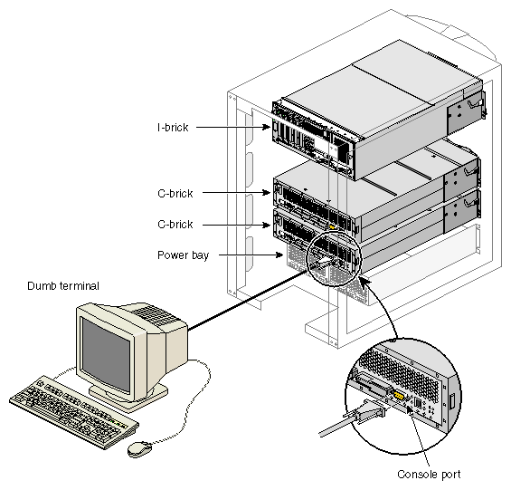
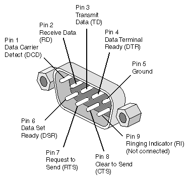
If you have a server without an L2 controller (such as a smaller SGI Origin 3200 server), you can connect a dumb terminal (or a PC with a terminal emulator) to the C–brick console port connector as shown in Figure 2-1. (Figure 2-2 shows the console port connector pinouts.)
If you have multiple C–bricks in a rack, connect your console to the bottom-most C–brick that is connected to an I–brick.
If you have a server with an L2 controller, always connect your console to the L2 controller.
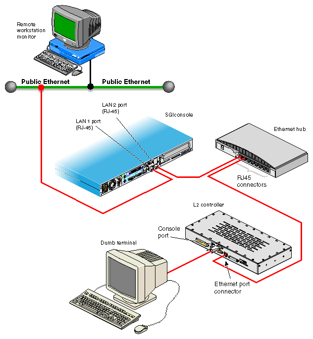
If you have an SGIconsole, connect it to the Ethernet port connector on the L2 controller as shown in Figure 2-3. (See your SGIconsole Hardware Connectivity Guide for instructions to connect your SGIconsole to the SGI Origin 3000 series servers with L2 controllers.) Optionally, you can connect a dumb terminal to the L2 controller console (RS-232) connector.
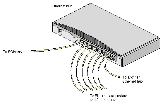
If you have a server with multiple L2 controllers, you can connect the SGIconsole to the Ethernet hub, to which the multiple L2 controllers are connected, as shown in Figure 2-4. See your SGIconsole Hardware Connectivity Guide for instructions to connect your SGIconsole to an SGI Origin 3000 series server.
The Ethernet hub, in turn, can be cascaded to another Ethernet hub. This is a good solution for an SGI Origin 3800 server system model, as you would have multiple tall (39U) racks, and each rack with C–bricks would have its own L2 controller.
Table 2-1. Console Connection Options
System Console Type
Server with No L2 Controller (Connect to Console Port on C–brick)
Server with No L2 Controller (Connect to L1 Port [USB] on C–brick)
Server with Single L2 Controller (Connect to Console Port on L2 Controller)
Server with Single L2 Controller (Connect to Ethernet Port on L2 Controller)
Server with Multiple L2 Controllers (Connect to Ethernet Hub)
Dumb terminal or PC with terminal emulator
Connection
N/A
Connection
N/A
N/A
SGIconsole
N/A
N/A
N/A
Connection
Connection
Besides the system console described in the previous section, you can add or replace the following hardware items on your SGI Origin 3000 series server system:
Peripheral component interface (PCI) cards into your I–brick or P–brick.
Disk drives to your D–brick.

Warning: You can add or replace only the items listed in this section. For your safety and for the protection of your server system, contact your SGI system support engineer (SSE) to install any hardware items not listed in this section 
Warning: Before installing, operating, or servicing any part of this product, please read the “Safety Instructions” in Appendix D.
The PCI-based I/O system, an industry standard for connecting peripherals to a processor, is the primary I/O system for the SGI Origin 3000 series servers.
The I–brick and P–brick subsystems provide PCI support for the SGI Origin 3000 server series systems. The I–brick provides five PCI slots. Normally, one of the five slots is reserved for a system PCI card.
If additional PCI slots are required beyond the I–brick's four remaining slots, a P–brick is configured into the system. The P–brick supports 12 PCI slots. Table 2-2 summarizes the maximum number of PCI slots available in the SGI Origin 3200, SGI Origin 3400, and SGI Origin 3800 server systems.
Table 2-2. PCI Slots Available
System | I/O Bricks | Maximum Available PCI Slots |
|---|---|---|
1 I–brick, 1 P–brick | 16 | |
1 I–brick, 7 P–bricks | 88 | |
1 I–brick, 63 P–bricks | 760 |
Table 2-3 shows the PCI cards supported and installable in your I–brick and P–brick.
Table 2-3. PCI Cards Supported
Marketing Code | Description |
|---|---|
PCI-SER-10002 | Serial card |
PCI-SCSI-DF-2P | Ultra SCSI high-voltage differential 2-port |
PCI-SCSI-U3-2P | Ultra3 SCSI low-voltage differential 2-port (3.3 V) |
PCI-FC-1POPT-A | Fibre channel with fiber optic cable, 66 MHz |
PCI-FC-1PCOP-A | Fibre channel with copper cable, 66 MHz |
PCI-ATMOC3-1P | ATM OC3 |
PCI-ATMOC12-1P | ATM OC12 |
PCI-GIGENET-C | Gigabit Ethernet (copper) |
PCI-GIGENET-OR | Gigabit Ethernet (optical) |
PCI-AUD-D1000 | Digital audio |
See “PCI Card Description and Installation” in Chapter 6 for detailed instructions for installing a PCI card.
The D–brick is a Fibre–Channel–based disk storage enclosure used to provide JBOD (just a bunch of disks) mass storage for all SGI Origin 3000 series server models.
See “Adding and Removing Disk Drive Modules” in Chapter 8 for detailed instructions for installing disk drive modules in the D–brick.
The following subsections describe how to power on and power off individual bricks or your entire SGI Origin 3000 series server.
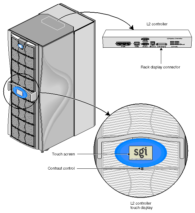
For servers with an L2 controller, you can power on and power off individual bricks and the entire system at the L2 controller touch display located on the front door of the server rack.
For servers with a system console (an SGIconsole or a dumb terminal), you can power on and power off individual bricks and the entire system at the system console.
If you are using an SGIconsole, you can monitor and manage your server from a remote location, and you can control and monitor your server using various software tools. See your SGIconsole documentation for information on the particular tools available.
The Embedded Support Partner (ESP) program enables you and your SGI system support engineer (SSE) to monitor your server remotely so as to resolve issues before they become problems. For details on this program, see “Using Embedded Support Partner (ESP)”.
This section describes how to prepare to power on your system, and describes how to power on your system by using either of the following:
L2 controller touch display
System console
To prepare to power on your system, follow these steps:
Check to ensure that the cabling between the PDU or PDS and the wall power-plug receptacle is secure.
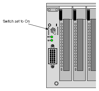
Make sure that the power switch on each individual brick that you want to power on is set to the 1 (On) position, as shown in Figure 2-5 for the I–brick. This starts the L1 controller for the brick(s) when the brick(s) is powered on. The 12V LED on the individual brick lights green when the L1 controller has powered on successfully.
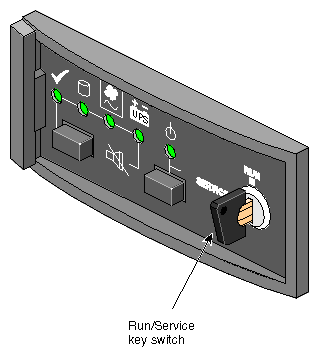
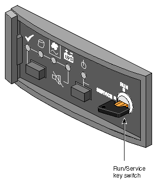
If you plan to power on a D–brick or the entire server, which includes a D–brick, make sure that the D–brick's RUN/SERVICE key switch on the ESI/Ops panel is set to RUN, as shown in Figure 2-6.
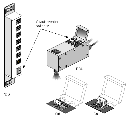
Make sure that the PDU or PDS circuit breaker switch shown in Figure 2-7 is turned on to give power to the server system when the server is powered on.

Note: Check that the brick LEDs turn on and light green and that your controllers display that the system is powered on for each segment of the procedure, which indicates that the powering on procedure is proceeding properly. If you have a problem during powering on and an error message appears on the L1 controller or the system console, see your online log files and Appendix C, “Controller Status and Error Messages” to learn what the error message indicates and what steps will resolve the problem.
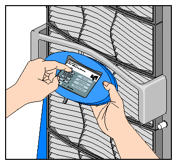
This section describes how to power on individual bricks or the entire system from your L2 controller touch display (rack display) shown in Figure 2-8, which is located on the front door of every tall rack with an L2 controller. If you have multiple racks whose L2 controllers are interconnected at an Ethernet hub, you can power on any brick in those racks, a partition, or the entire system at any L2 controller touch display available on your server.
For instructions on navigating the L2 controller touch display, see “Using the L2 Controller Touch Display” in Chapter 3.
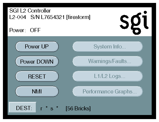
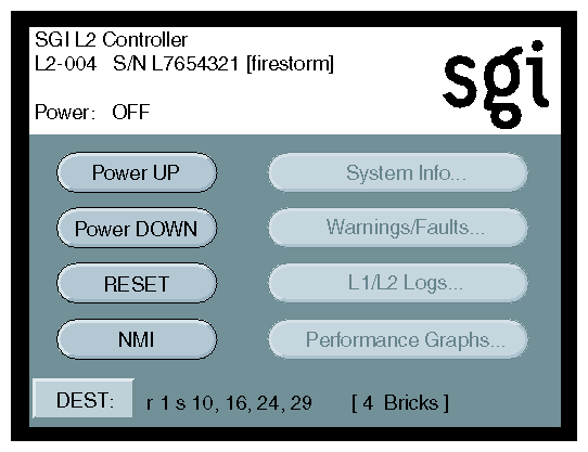
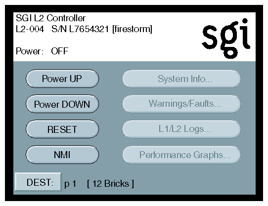
The home window, shown in Figure 2-9, displays the following items:
Rack number (L2-004) of the L2 controller to which the L2 controller touch display is connected.
L2 controller system serial number (L7654321).
Server system name in parentheses (firestorm).
Power status (Power: OFF) for the bricks designated in the destination (DEST) field, which indicates all slots in all racks (r * s *), which amounts to 56 bricks.
To power on selected bricks, a partition, or the entire server, follow these steps:
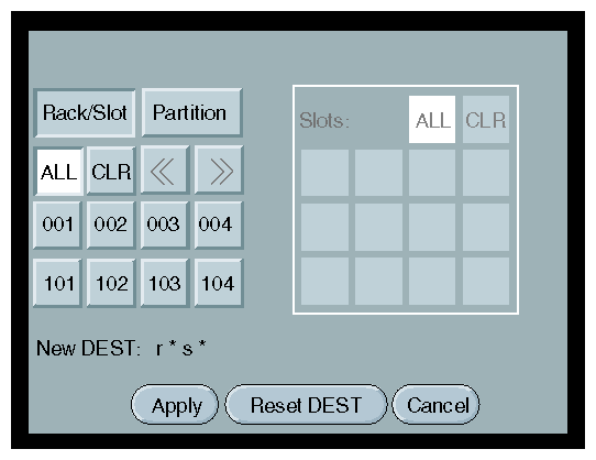
Select the DEST button to select the bricks or partition you want to power on. The destination selection window, shown in Figure 2-10 appears.
The bricks are selected by their rack and slot/bay (unit position) number, or by partition. Select ALL in the display if you want to power on all the bricks in all the racks and slots in the server. You can also select the bricks in all the slots of multiple racks, but you cannot select slots for multiple racks.
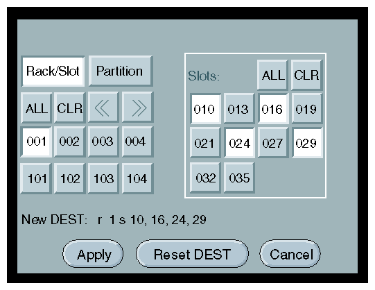
If you want to select individual bricks to power on, select the rack from which you want to select bricks from the Rack/Slot segment of the display. For example, if you select 001, a Slots section on the window with all the slots for bricks in rack 001 appears, as shown in Figure 2-11.
Select slots from the Slots section (Figure 2-11 shows slots 010, 016, 024, and 029 selected). The New DEST setting changes to reflect your selections. After you make your selections, select Apply. The home window appears, which displays r 1 s 10, 16, 24, 29 in the DEST field, as shown in Figure 2-12. This indicates you have selected slots (bricks) 10, 16, 24, and 29 from rack 1 to power on.
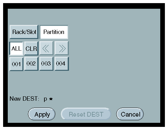
If you want to power on a partition, select Partition from the destination selection window. The partition selection window, shown in Figure 2-13, appears.
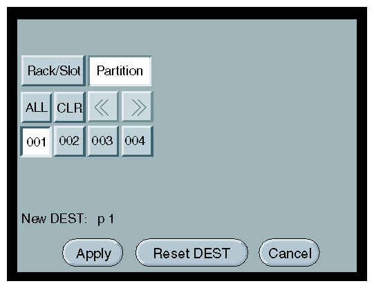
You can select all partitions by selecting ALL on the partition selection window, or you can select a single or multiple partitions by selecting the individual partition numbers. Figure 2-14 shows partition 001 selected.
The New DEST field shows p 1, which indicates that partition 001 was selected as the new destination. If you select Apply, your selection is confirmed and the home window, shown in Figure 2-15, appears. The DEST field shows p 1 [12 Bricks], which indicates that all 12 Bricks belonging to partition 1 is the new destination.
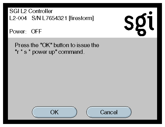
After you have selected the destination of the bricks you want to power on, select Power UP on the home window, and the Power UP confirmation window, shown in Figure 2-16, appears. This window indicates which bricks will receive the Power UP command. In this example, it indicates that it will power on all slots (bricks) in all racks (r * s*). If you select OK, the power–up operation is confirmed, and the home window appears. Selecting Cancel stops the power–on operation, and the home window appears.
The power-on procedure at a system console varies with your server setup:
If you have a system console connected to a server with a hardware L2 controller, you can toggle between L2, L1, and console mode, power on your server with L1 or L2 controller commands, and monitor the power-on activity by changing to the console mode.
If you have a system console without a hardware L2 controller, you can toggle between L1 and console mode. This enables you to power on your server with L1 commands and view the activity by changing to the console mode.
For detailed instructions on using a system console running L2 software, see “About the L2 Controller Firmware” in Chapter 3. For detailed instructions on using the L2 mode, see “Operating L2” in Chapter 3. For detailed instructions on using a system console using the L1 mode, see “Operating L1” in Chapter 3.
The following sections describe how to power on your system using the L2 mode and the L1 mode.
To power on your system while in the L2 mode, follow these steps:
From the L2 prompt (L2>), power on an individual brick by typing the following command. (If you want to power on the entire server, proceed to the next step.)
L2> r <rack#> s <slot#> pwr u
For example, to power on a C–brick in rack 1, slot 10, type the following:
L2> r 1 s 10 pwr u
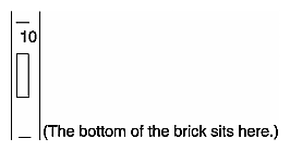
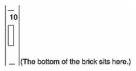
The slot number is the unit position number located on the rack, slightly above where the bottom of the brick sits. Each rack unit position number is located toward the top of the two lines that mark off the unit position that the number represents. For example, the rack numbering for a brick located in slot 10 would appear on the left front side of the rack as shown in Figure 2-17:
If you want to power on several selected bricks from a rack at the same time, you must type the rack number followed by the slot numbers of the bricks you want to power on. For example, to power on bricks in slots 7 and 10 for rack 4, type the following:
L2> r 4 s 7,10 pwr u
If you want to power on a brick for several racks, you must type the number of the racks followed by the slot number of the brick you want to power on for all the racks. For example, to power on the brick in slot 10 for racks 3 and 4, type the following:
L2> r 3, 4 s 10 pwr u

Caution: To avoid problems with your system, do not try to power on multiple slots for multiple racks at the same time. If you want to power on the entire server, type the following command:
L2> pwr u
(The default setting for the pwr u command is all racks and all slots.)
From the L2 prompt, display the system configuration by typing the following command:
L2> config
This command lists the bricks in the system and each brick's system controller address.
The L1 controller display for each brick should display L1 running once the power on procedure starts.
| Note: If you have a problem during powering on and an error message appears on your console display, see Appendix C, “Controller Status and Error Messages” to learn what the error message indicates and what steps will resolve the problem. |
The only time you would want to power on from the L1 mode is when you do not have the L2 mode available on your system.
To power on your system while in the L1 mode, follow these steps:
The prompt on your system will be the rack and slot number of the C–brick to which you have connected your console. If you want to power on the C–brick (003c01 in our example) indicated in the prompt, type the following command. (If you want to power on the bricks connected to the C–brick, proceed to the next step.)
003c01-L1> power up
If you want to power on the bricks connected to the C–brick, type the following command:
oo3c01-L1> * power up
(* indicates all)
From the L1 prompt, display the brick configuration information by typing the following command:
003c01-L1> config
In L1 mode, you can obtain only limited information about the system configuration. A C–brick only has information about its attached I/O brick and, if another C–brick is attached to the I/O brick, information about that C–brick and its attached I/O brick. An I/O brick only has information about its attached C–brick and an R–brick only has information about itself.
The L1 controller display for the brick should display L1 running once the power–on procedure starts.
Individual bricks and your entire server system can be powered off from the L2 controller touch display located on the front door of the system or from the server system console.
Follow these steps to prepare to power off:
Check to assure that the cabling between the PDU or PDS and the wall power-plug receptacle is secure.

Note: Check that the LEDs turn off and that your controllers display that the system is powering off for each segment of the procedure, which indicates that the powering off procedure is proceeding properly. If you have a problem during powering off and an error message appears on your L2 controller touch display or your console, see your system's online log files and Appendix C, “Controller Status and Error Messages” to learn what the error message indicates and what steps will resolve the problem. If you are going to power off the D–brick or the entire system, make sure that the D–brick's RUN/SERVICE key switch on the ESI/Ops panel is set to SERVICE, as shown in Figure 2-18.
This section describes how to power off individual bricks or the entire system from the L2 controller touch display located on the front door of any server tall rack with an L2 controller. If you have multiple racks whose L2 controllers are interconnected at an Ethernet hub, you can power on any brick in those racks or the entire system at any L2 controller touch display available on your server.
For instructions on navigating the L2 controller touch display, see “Using the L2 Controller Touch Display” in Chapter 3, in Chapter 3, “System Control ”.
The home window shown in Figure 2-19 displays the following items:
Rack number (L2-004) of the L2 controller to which the L2 controller touch display is connected.
L2 controller system serial number (L7654321).
Server system name in parentheses (firestorm).
Power status (Power: OFF) for the bricks designated in the destination (DEST) field, which indicates all slots in all racks (r * s *), which amounts to 56 bricks in this example.
To power off selected bricks, a partition, or the entire server, follow these steps:
Select the DEST button to select the bricks or partition you want to power on. The destination selection window, shown in Figure 2-20, appears.
The bricks are selected by their rack and slot/bay (unit position) number, or by partition. Select All in the display if you want to power down all the bricks in all the racks and slots in the server. You can also select the bricks in all the slots of multiple racks, but you cannot select slots for multiple racks.
If you want to select individual bricks to power down, select the rack from which you want to select bricks from the Rack/Slot segment of the display. For example, if you select rack 001, a Slots section on the window with all the slots for bricks in rack 001 appears, as shown in Figure 2-21.
Select slots from the Slots section (Figure 2-21 shows slots 010, 016, 024, and 029 selected). The New DEST setting changes to reflect your selections. After you make your selections, select Apply. The home window appears, which displays r 1 s 10, 16, 24, 29 in the DEST field, as shown in Figure 2-22. This indicates that you have selected slots (bricks) 10, 16, 24, and 29 from rack 1 to power off.
If you want to power off a partition, select Partition from the destination selection window. The partition selection window, shown in Figure 2-23, appears.
You can select all partitions by selecting ALL on the partition selection window, or you can select a single or multiple partitions by selecting the individual partition numbers. Figure 2-24 shows partition 001 selected.
The New DEST field shows p 1, which indicates partition 001 was selected as the new destination. If you select Apply, your selection is confirmed and the home window, shown in Figure 2-25, appears. The DEST field shows p 1 [12 Bricks], which indicates that all 12 Bricks belonging to partition 1 is the new destination.
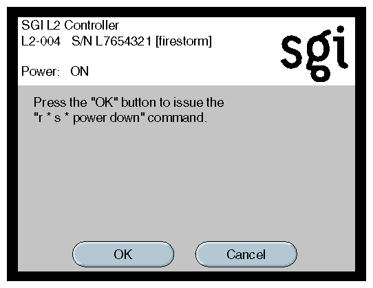
After you have selected the destination of the bricks you want to power off, select Power DOWN from the home window, and the Power DOWN confirmation window, shown in Figure 2-26, appears. This window indicates which bricks will receive the Power DOWN command. In this example, it indicates that it will power off all slots (bricks) in all racks (r * s*). If you select OK, the power–off operation is confirmed and the home window appears. Selecting Cancel stops the power–off operation and the home window appears.
The power–off procedure at a system console varies with your server setup:
If you have a system console connected to a server with a hardware L2 controller, you can toggle between L2, L1, and console mode, power off your server with L1 or L2 controller commands, and monitor the power-off activity by changing to the console mode.
If your system console is running on a server that has no hardware L2 controller, you can toggle between L1 and console mode. This enables you to power off your server with L1 commands and view the activity by changing to the console mode.
For detailed instructions on using a system console running L2 software, see “About the L2 Controller Firmware” in Chapter 3. For detailed instructions on using the L2 mode, see “Operating L2” in Chapter 3. For detailed instructions on using a system console in the L1 mode, see “Operating L1” in Chapter 3.
The following sections describe how to power off your system in the L2 mode and the L1 mode.
To power off your system while in the L2 mode, follow these steps:
From the L2 prompt (L2>), power off an individual brick by typing the following command. (If you want to power off the entire server, proceed to the next step.)
L2> r <rack#> s <slot#> pwr d
For example, to power off a C–brick in rack 1, slot 10, type the following:
L2> r 1 s 10 pwr d
The slot number is the unit position number located on the rack, slightly above where the bottom of the brick sits. Each rack unit position number is located toward the top of the two lines that mark off the unit position the number represents. For example, the rack numbering for a brick located in slot 10 would appear on the left front side of the rack as shown in Figure 2-27:
If you want to power off several selected bricks from a rack at the same time, you must type the rack number followed by the slot numbers of the bricks you want to power off. For example, to power off bricks in slots 7 and 10 for rack 4, type the following:
L2> r 4 s 7,10 pwr d
If you want to power off a brick for several racks, you must type the number of the racks followed by the slot number of the brick you want to power off for each rack. For example, to power off the brick in slot 10 for racks 3 and 4, type the following:
L2> r 3, 4 s 10 pwr d

Caution: To avoid problems with your system, do not try to power off several slots for several racks at the same time. If you want to power off all the bricks in all the racks, type the following command:
L2> pwr d
(The default setting for power off is all racks and all slots.)
From the L2 prompt, display the brick configuration information by typing the following command:
L2> config
This command lists all the bricks in the system and each brick's system controller address.
The L1 controller display for each brick should display L1 running once the power down procedure starts.
| Note: If you have a problem during powering on and an error message appears on your console display, see Appendix C, “Controller Status and Error Messages” to learn what the error message indicates and what steps will resolve the problem. |
The only time you would want to power off from the L1 mode is when you do not have L2 software available on your system.
To power off your system while in the L1 mode, follow these steps:
The prompt on your system will be the rack and slot number of the C–brick to which you have connected your console. If you want to power off the C–brick (003c01 in our example) indicated in the prompt, type the following command. (If you want to power off the bricks connected to the C–brick, proceed to the next step.)
003c01-L1> power down
If you want to power off the bricks connected to the C–brick, type the following command:
oo3c01-L1> * pwer down
(* indicates all)
From the L1 prompt, display the brick configuration information by typing the following command:
003c01-L1> config
In L1 mode, you can obtain only limited information about the system configuration. A C–brick only has information about its attached I/O brick and, if another C–brick is attached to the I/O brick, information about that C–brick and its attached I/O brick.
An I/O brick only has information about its attached C–brick and an R–brick only has information about itself.
Embedded Support Partner (ESP) automatically detects system conditions that indicate potential future problems and then notifies the appropriate personnel. This enables you and SGI system support engineers (SSEs) to proactively support systems and resolve issues before they develop into actual failures.
ESP enables users to monitor one or more systems at a site from a local or remote connection. ESP can perform the following functions:
Monitor the system configuration, events, performance, and availability.
Notify SSEs when specific events occur.
Generate reports.
ESP also supports:
Remote support and on-site troubleshooting.
System group management, which enables you to manage an entire group of systems from a single system.
You can monitor your SGI Origin 3000 series server from the following sources:
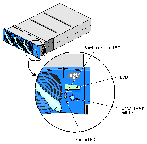
On the L1 controller's display located at the right-hand corner of each brick (except the D-brick), as shown in Figure 2-28, you can monitor brick items. For example, you can see if the fans on a particular brick are operating properly.
On the L2 controller touch display on the front door of the tall rack shown in Figure 2-29, you can see the L1 status and error messages for each brick in the rack.
The L2 controller can connect to other L2 controllers in other racks via its Ethernet port. For details on how to interconnect multiple L2 controllers, see Chapter 3, “System Control ”.
If your server has an L2 controller, you can connect the SGIconsole to the Ethernet port on the L2 controller. If you have multiple L2 controllers, connect the SGIconsole to an Ethernet hub that is connected to the Ethernet port of the multiple L2 controllers. You will need to connect either a local or remote workstation to monitor the servers, as shown in Figure 2-30.
Optionally, you can connect a dumb terminal (or PC with terminal emulator) to the L2 controller console port as shown in Figure 2-30.
These console connections to the L2 controller enable you to view the status and error messages generated by the L1 controllers on your server rack. You can also use these consoles to input L1 and L2 commands to manage and monitor your system.

Note: The SGIconsole enables you to use various software tools to manage and monitor your system. See the SGIconsole Start Here guide for descriptions of these tools and for references to other documents for information on using these tools. If your system does not have an L2 controller, you can connect a dumb terminal to the C–brick console port. If you have multiple C–bricks in a rack, connect the dumb terminal to the bottom-most C–brick that is connected to an I–brick as shown in Figure 2-31. This connection enables you to view the status and error messages generated by the L1 controller and to enter L1 commands to manage and monitor your system.
For explanations of the L1 and L2 commands, see Appendix B, “System Controller Commands”.
