The following sections in this chapter describe the function and physical components of the D–brick. These sections also explain how to operate, how to add and replace disk drive modules, and how to troubleshoot the D–brick:
The D–brick is a module used to add JBOD (just a bunch of disks) storage to SGI Origin 3000 series of servers. It supports a maximum of 12 disk drives. (A minimum of 2 disk drives in specified slot locations described later in this chapter are required for D–brick management.) The D–brick provides the “hot-plugging” feature that enables you to add, replace, or take out disk drive modules from the D–brick without powering off the brick.
| Note: The D–brick is added only as JBOD, but if you require RAID storage, ask your SGI sales representative about SGI's RAID storage products, such as the TP 9100 and TP9400, to meet your needs. |
Besides the disk drives, the D–brick includes the following modules and functionality:
Two power supply/cooling modules. To provide power and cooling for the D–brick. Using a Y cable, these two power supplies bypass the power bay, which provides only 12 VDC and 48 VDC, and connect directly to a single PDS outlet connector to get the 220 VAC it needs.
Enclosure system interface/operator panel (ESI/ops). To operate, monitor, and troubleshoot the D–brick.
Two FC-AL loop resiliency circuit (LRC) I/O modules. Each module provides input and output connectors to all 12 disk drives. The modules provide connection to your system console or to another D–brick to daisy chain two or more D–bricks together.
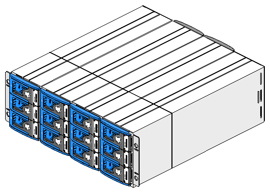
Figure 8-1 shows a front view of the D–brick, with the full complement of 12 disk drive modules. You can have a minimum of 2 to a maximum of 12 disk drives. The left lowermost and right lowermost drive bays must have a disk drive module to enable management of the D–brick. See “Required Drives ” and “Operating Panel, Modules, Connectors, and LEDs on D–brick Rear Panel” for detailed information about the required disk drive modules and their locations.
The D–brick uses disk technology that allows you to replace a disk while the system continues to run. This “hot-plugging” must be done under controlled circumstances; see “Adding and Removing Disk Drive Modules” for more information.
The disk drives are also dual-ported and can be configured on two separate loops to increase availability, in case one loop becomes disabled.
Disk–drive fillers are provided for all unused disk drive bays and are required to maintain a balanced airflow in the D–brick.
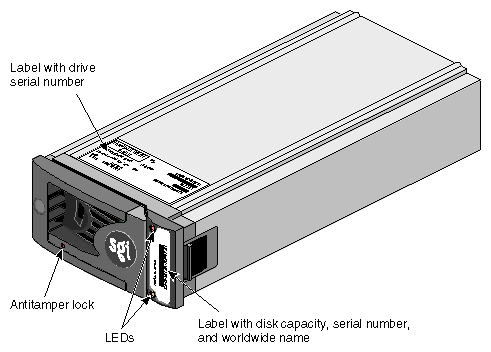
Figure 8-2 shows a close-up picture of the disk drive module, which consists of a hard disk mounted in an aluminum carrier. Each drive bay in the front of the D–brick houses a single 1.6-in. high (4.064 cm), 3.5-in. (8.89 cm) disk drive in its wrapper, or a 1-in. (2.54 cm) high drive, which has a foam filler.
The following items are found on the disk drive module:
Labels. The label on the front of the drive has the drive capacity (for example, FCAL 9.17GB), the serial number, and worldwide name . The serial number of the drive is also on a label on the top of the carrier.
LEDs. Each drive carrier has two LEDs, an upper (green) and lower (amber). In normal operation, the green LED is on and flickers as the drive operates. The amber LED illuminates when the drive is faulty.
Antitamper lock. The drive carrier has an antitamper lock that disables the normal latch action of the handle for security purposes. A key to lock the disk drive is provided with each D–brick. A red indicator is visible in the center rectangular aperture in the handle if the antitamper lock is locked, and a black indicator is visible when the lock in unlocked.
The extruded aluminum carrier (canister) provides thermal conduction, radio frequency and electromagnetic induction protection, and maximum physical protection of the drive.
The drive module cap has an ergonomic handle that provides the following functions:
Camming of the carrier into and out of the drive bays
Positive spring loading of the drive/backplane connector
The drive carrier has an antitamper lock that disables the normal latch action of the handle; it is fitted in the drive carrier handle, as shown in Figure 8-2. The lock is set through the hole in the lower part of the handle trim. An indicator shows the setting:
When the drive is locked, a red indicator is visible in the center rectangular aperture in the handle.
When the drive is unlocked, a black indicator is visible.
The antitamper lock setting is changed with a key through the small round cutout in the lower part of the handle trim piece. (A key is included with each D–brick.) Changing the setting is explained in “Adding a Disk Drive Module” and in “Adding and Removing Disk Drive Modules”.
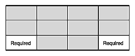
Figure 8-3 shows the location of the drives required by the ESI/ops panel, namely drive bays 1/3 and 4/3. “Operating Panel, Modules, Connectors, and LEDs on D–brick Rear Panel” has full details about bay numbering.
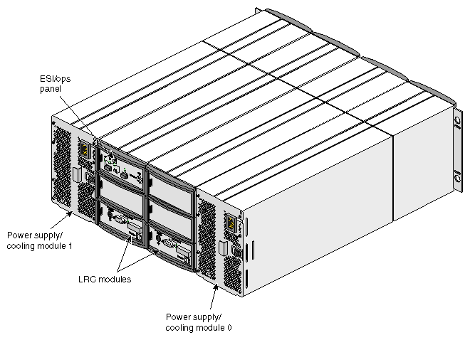
Figure 8-4 shows the location of the power-on switch, connectors, and LEDs on the D–brick rear panel.
The D–brick is shipped with the following component modules, shown in Figure 8-4, as standard equipment:
Two power supply/cooling modules (modules 0 and 1)
One enclosure system interface/operator panel (ESI/ops)
Two loop resiliency circuit (LRC) I/O modules
These subsections provide details about the chassis and the component modules:
The D–brick chassis consists of two extended aluminum assemblies with a midplane PCB between them. Each chassis assembly contains 12 bays; a bay is defined as the space required to house a single 3.5-in. disk drive (1.6 in. high, or 1 in. high with a foam filler) in its carrier module. The two standard power supplies accommodate multiple bay spaces (three). The midplane PCB provides logic level signal and low-voltage power distribution paths.
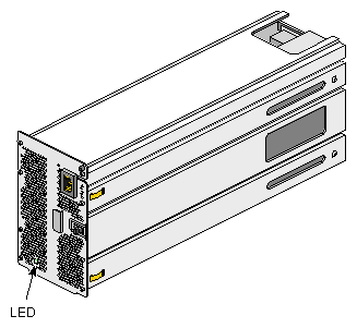
Two 550-W power supply/cooling modules are mounted in the rear of the D–brick. Figure 8-5 shows a module. The module contains two fans as well as the power supply and its associated electronics. The fans derive power from the chassis midplane, not from the power supply itself.
Power supply voltage operating ranges are nominally 115 V or 230 V, selected automatically.
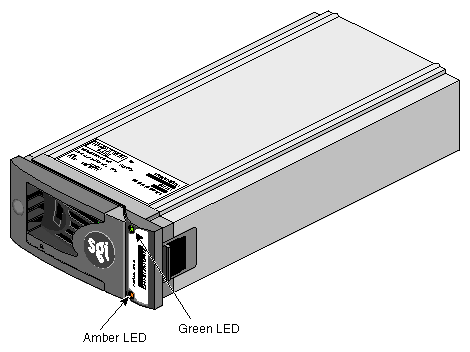
An LED on the front panel of the power supply/cooling module indicates the status of the power supply and the fan. Green indicates normal operation and amber indicates a fault condition.
With a Y-cable, the D–brick power supplies are connected directly to an output connector on the power distribution strip (PDS) to get the required 220 VAC.
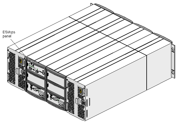
The ESI/ops panel module provides the D–brick with a microcontroller for monitoring and controlling all elements of the D–brick. Each element (power, cooling, temperature, device status) is interfaced to the processor using an I2C (I square C) bus.
Figure 8-6 shows the location of the ESI/ops panel in the D–brick.
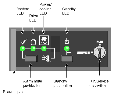
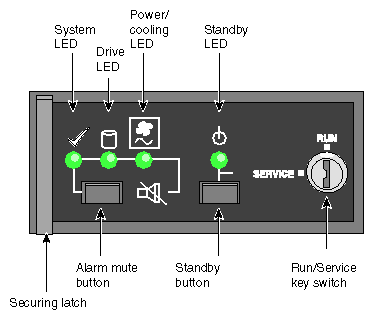
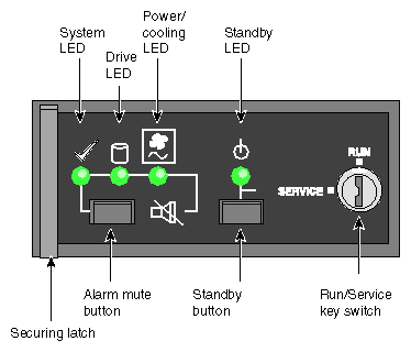
Figure 8-7 shows details of the ESI/Ops panel.
The ESI/ops panel shows a consolidated status for all modules. Table 8-1 summarizes the functions of the LEDs on the ESI/ops panel, as well as those on other modules in the D–brick.
Table 8-1. D–brick LED Indicators
LED | Meaning |
|---|---|
Green, steady | Positive condition |
Green, flashing | Disk drives: data activity |
Alternating green and amber, flashing | Noncritical condition |
Amber, steady | Fault |
In addition to the indicators on the ESI/ops panel, each module type has its own status LED(s). Using the LEDs for troubleshooting is explained in “Using D–brick LEDs for Troubleshooting”.
Other features of the ESI/ops panel are as follows:
Key switch. Activates run or service mode, as explained in “Key Switch for Starting the D–brick ”.
Standby button. Activates standby mode when the key switch is in the Service position; see “Powering the D–brick On or Off”.
Alarm mute button. Mutes the alarm; see “Audible Alarm”.
The ESI/ops panel module firmware includes SCSI enclosure services (SES), which monitor the modules in the D–brick and control the ESI/ops panel LEDs. The ESI/ops panel requires two disk drives in specific drive bays to serve as conduits for information from the D–brick to the ESI/ops panel module.
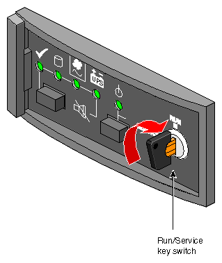
For general use, the D–brick is started by turning the key switch on the far right of the ESI/ops panel to the RUN position; the key is in this position when the D-brick is shipped. For specific instructions on starting and stopping the D–brick, see “Powering the D–brick On or Off”.
The audible alarm on the ESI/ops panel sounds when a fault state is present. Pressing the alarm mute button reduces the volume of the alarm, but beeps at approximately 10-second intervals to indicate that a fault state is still present. The mute button is beneath the indicators on the ESI/ops panel (see Figure 8-7).
See “Using the Alarm for Troubleshooting” for a list of the conditions that activate the alarm.
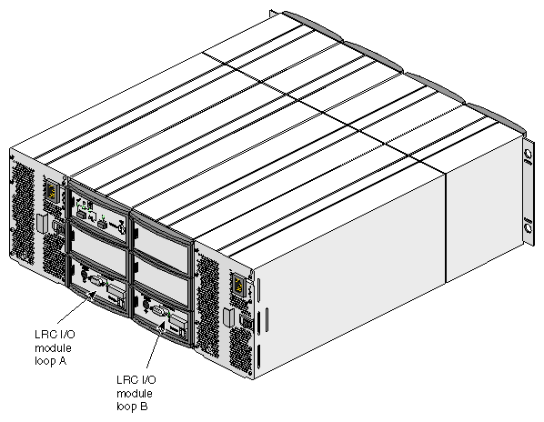
The D–brick is shipped with two FC-AL loop resiliency circuit (LRC) I/O modules, which make dual (redundant) data paths possible.
Figure 8-8 shows the locations of the I/O modules.
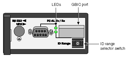
Figure 8-9 shows features of the I/O module panel.
Each I/O module has the following connectors and LEDs:
DB-9 connector. This output connector can be cabled into a second D–brick's GBIC port connector to daisy-chain the two D–bricks.
The DB-9 port connector on the I/O module panel has an LED indicating its status. The LED glows a steady green to indicate a good FC-AL signal on the attached cable. The LED lights amber when a problem with the connection is detected.
GBIC Port. This Gigabit Interface Connector (GBIC) port is an input connector used to cable in an I/O brick on the server to the D–brick. This port connects to a host bus adapter (HBA) PCI card in an I–brick or P-brick on the server. You can also connect a cable coming from a second D–brick's DB-9 connector into the GBIC port to daisy-chain the two D–bricks.
You insert an HSSDC GBIC module into the GBIC port to make the cabling connection.
The GBIC port connector has an LED indicating its status. The LED glows a steady green to indicate a good FC-AL signal on the attached cable. The LED lights amber when a problem with the connection is detected.
ID range selector switch. Each I/O module has an ID range selector switch for the system ID. Disk drive IDs are based on this ID. The legal address ID settings are 1 through 7.
At initial startup, each I/O module controls a separate loop of six drives
Make sure that the ambient temperature is within the specified operating range of 10 ˚C to 40 ˚C (50 ˚F to 104 ˚F). If drives have been recently installed, make sure that they have had time to acclimatize before operating them.
Make sure that the D–brick's power supply/cooling modules' power connectors are cabled directly, with a Y cable, to an outlet connector of the power distribution strip (PDS).
For an unattended installation in which the D–brick is required to power on whenever AC power is present, the RUN/SERVICE key switch on each ESI/ops panel of each enclosure you are operating should be in the RUN position. The key switches are in this position when the D-bricks are shipped (see Figure 8-10).
If the RUN/SERVICE key switch is in the RUN position, the enclosure powers on when power reaches the enclosure.
If the RUN/SERVICE key switch is in the RUN position and power is interrupted, the enclosure returns to the power-on condition when power is restored.
In run mode, the standby button is disabled.
When you power on the system, the standby LED on each ESI/ops panel (see Figure 8-11) in each enclosure you are operating should turn green. If it does not, check that the power supply/cooling modules in the enclosure are correctly cabled to the rack PDS.
When you power on the system, check ESI/ops panel LEDs for system status. Under normal conditions, these LEDs should all be illuminated constant green. If a problem is detected, the ESI processor in the operator panel changes the relevant LED from green to amber. See “Solving Initial Startup Problems” and “Solving Power Supply/Cooling Problems”.
Other modules in the D–brick also have LEDs, which are described in “Using D–brick LEDs for Troubleshooting”.
The D–brick toggles between standby mode (all drives are powered off) and run (operation) mode whenever the standby button is pressed.
After making sure users are off the affected systems, power off the D–brick as follows:
Turn the key switch to the SERVICE position and then press the standby button for two seconds.

Note: To power on the D–brick again from this setting, press the standby button for two seconds again. Remove power at the power source: unplug the D–brick from the PDS.
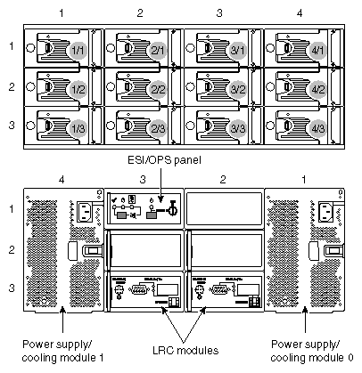
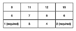
Figure 8-12 shows the correct positions of the disk drive modules and the enclosure bay numbering convention. A bay is defined as the space required to house a single 3.5-in. disk drive in its carrier module.
The D–brick is 4 bays wide by 3 bays high.
The disk drive bays, located in front, are numbered 1 to 4 from left to right and 1 to 3 from top to bottom. Drives in bays 1/3 and 4/3 are required for D–brick management; these bays must always be occupied.
The rear bays are numbered 1 to 4 from right to left and 1 to 3 from top to bottom.
Module locations are identified by combining the column and row numbers (top and side numbers in Figure 8-12). For example, the ESI/ops panel is in rear bay 3/1 (third column from right, top row).
This section explains how to add or remove a disk drive module in the following sections:
Note the following:
All disk drive bays must be filled with either a disk drive module or a drive filler; no bay should be left completely empty.
The drives in bays 1/3 and 4/3 are required for enclosure management; these bays must always have a disk drive.
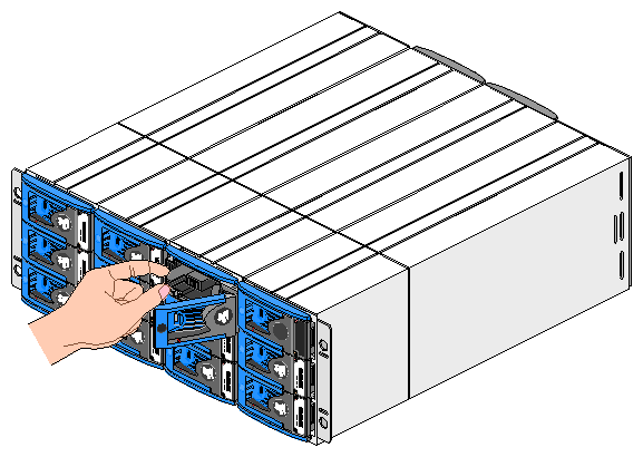
Install drives in the order shown in Figure 8-13. Generally, after the two required bays are occupied, drive bays are filled starting at the bottom of the D–brick .
Follow these steps to add a new disk drive module to the D–brick:
Make sure that enough disk drives and disk–drive fillers have been ordered to occupy all bays.
For each new drive, carefully open the bag containing the drive.

Warning: The disk drive handle might have come unlatched in shipment and might spring open when you open the bag. As you open the bag, keep it a safe distance from your face. Place the disk drive modules on an antistatic work surface, and make sure that their antitamper locks are disengaged (unlocked). A disk drive module cannot be installed if its antitamper lock is activated outside the enclosure.
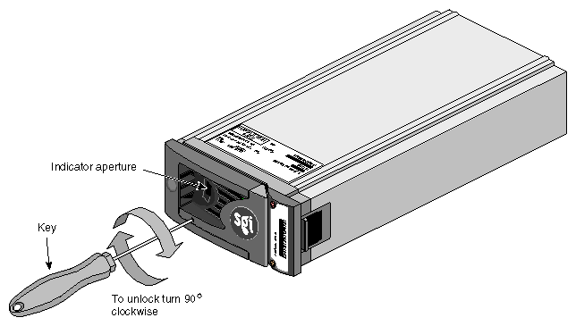
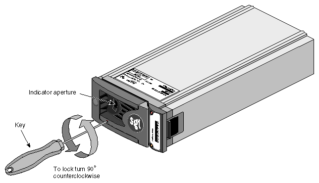
Drives are shipped with the locks set in the unlocked position. However, if a drive is locked, insert the key (included with the disk drive) into the socket in the lower part of the handle trim and turn it 90 degrees clockwise until the indicator visible in the center aperture of the handle shows black. See Figure 8-14.
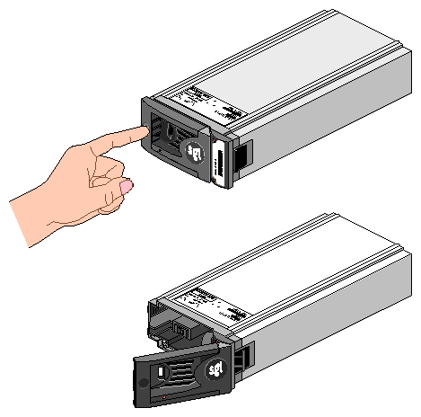
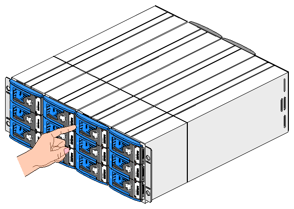
Release the disk drive module handle by pressing on the small indentation on the left of the module front (see Figure 8-15).
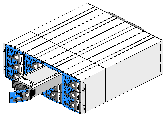
Insert the disk drive module into the chassis, as shown in Figure 8-16.

Note: The drive modules are not keyed. Make sure you are inserting the drive module in the correct orientation. Push the disk drive module gently into the chassis until it is stopped by the camming lever on the right of the module, as shown in Figure 8-17.
Press on the drive handle to seat the drive. The camming lever on the right of the module engages with a slot in the chassis, as shown in Figure 8-18.
Continue to push firmly until the handle fully engages with the module cap. You should hear a click as the latch engages and holds the handle closed.
Repeat steps 2 through 7 for all drive modules to be installed.
When you have finished installing all drives, activate the drive antitamper lock on each one:
Carefully insert the lock key provided into the cutout in the handle trim. See Figure 8-19.
Rotate the key 90 degrees counterclockwise until the indicator in the handle shows red.
Remove the key and store it.
Fit all empty drive bays with disk–drive fillers. The drive handle and camming mechanism operate the same way as for disk drives.
If an LED indicates that a disk drive is defective, follow these steps to remove the faulty drive:
Make sure enough disk drives and disk–drive fillers are available to occupy all bays.
Make sure users are off the affected systems; back up data if necessary.

Note: Replace disk drive modules one at a time, Make sure the faulty drive has spun down.

Caution: Damage can occur to a drive if it is removed while still spinning. Using the key, turn the antitamper lock to the off position:
Carefully insert the lock key provided into the cutout in the handle trim, as shown in Figure 8-14.
Rotate the key 90 degrees clockwise until the indicator in the handle shows black.
Remove the key and store it.
Release the handle by pressing on the small indentation area on the left of the module front.
Gently withdraw the module approximately 25 mm (1 in.) and wait 30 seconds.
Withdraw the module from the drive bay. Replace the drive immediately; follow instructions in “Adding a Disk Drive Module”.
If you are replacing a module in a LUN that uses a hot spare, note the location of the replacement module; it is the new hot spare.
The D–brick includes a processor and associated monitoring and control logic that allow it to diagnose problems within the D–brick's power, cooling, and drive systems.
The SES (SCSI enclosure services) processor is housed in the ESI/ops panel module. The sensors for power, cooling, and thermal conditions are housed within the power supply/cooling modules. Each module in the D–brick is monitored independently.
This section consists of the following subsections:
-

Note: If a fault is indicated on the ESI/ops panel, see Table 8-2 in “Using D–brick LEDs for Troubleshooting” and then see the section referenced within that table.
If cords are missing or damaged, plugs are incorrect, or cables are too short, contact your supplier for replacements.
If the D–brick alarm sounds when you power on the SGI Origin 3000 server (or the D–brick, if it has been powered off separately), one of the following conditions exists:
A fan is slowing down. See “Solving Power Supply/Cooling Problems” for further checks to perform.
There is an over temperature or thermal overrun condition. See “Solving Power Supply/Cooling Problems”.
There is a D–brick fault. See “Solving Problems Indicated by ESI/Ops Panel LEDs”.
If an amber disk drive module LED drive fault is on, there is a drive fault. See Table 8-3.
This section summarizes LED functions and gives instructions for solving D–brick problems in these subsections:
Figure 8-20 shows details of the ESI/ops panel.
Table 8-2 summarizes functions of the LEDs on the ESI/ops panel.
Table 8-2. ESI/Ops Panel LEDs and Troubleshooting
LED | Off | Green Steady | Green or Amber Flashing | Amber Steady | Remedy | |
|---|---|---|---|---|---|---|
Power is off, or standby mode is selected. | All ESI functions OK. | System configuration error. | ESI / I2C function failure. | See “Solving Problems Indicated by ESI/Ops Panel LEDs” . | ||
Power is off, or standby mode is selected. | All drives OK. | Drive fault (alternating green and amber). Note: ESI polling causes flash at regular interval. | N/A | Replace the drive as explained in “Adding and Removing Disk Drive Modules” . | ||
Power is off, or standby mode is selected. | All power and fans OK. | Not used. | See “Solving Power Supply/Cooling Problems” . Contact service provider for replacement. | |||
Standby | No AC power is supplied. | Power is good, or standby status is selected. | Not used. | Storage system is in standby mode due to ESI thermal shutdown. | See “Thermal Alarm” . |
Note the following:
If all LEDs on the ESI/ops panel flash simultaneously, see “Using Test Mode”.
If test mode has been enabled (see “Using Test Mode”), the amber and green drive bay LEDs flash for any non-muted fault condition.
The LED for the uninterruptible power supply (UPS) is covered with a sticker. This LED lights whether or not a UPS is present. Use of a UPS is not supported in this release. Leave the sticker in place.
If the system status LED on the ESI/ops panel is amber and the alarm is sounding, the ESI processor has detected an internal fault, such as failure of an internal communications path. Follow these steps:
Check if the LEDs on the power supply/cooling modules are amber. If a PSU error is present, there might be a communications problem with that power supply/cooling module. Contact your service representative for a replacement.
Check if the disk drive module LEDs are amber. If none are, there might be either an ESI processor problem or a chassis midplane problem. Contact your service provider.
See also “Thermal Shutdown”.
If the alarm is sounding, the power supply/cooling LED on the ESI/ops panel is amber, and the LED on one or both power supply/cooling modules is amber, the cause is one of the following:
To troubleshoot the problem, follow these steps:
Check the power connection to the power supply/cooling module.
If possible, reduce the ambient temperature. If the problem persists, contact your service provider.
If one of the power supply/cooling modules is missing or defective, all of the following occur:
Alarm sounds.
System LED on the ESI/ops panel flashes.
Power supply/cooling module LED remains illuminated.
If these warnings occur, check the LED on the power supply/cooling module. If it is amber, contact your service representative.
Figure 8-21 shows the location of the LED on the power supply/cooling module.
If this LED is amber, or if the power/cooling LED on the ESI/ops panel is amber and the alarm is sounding, contact your service provider.
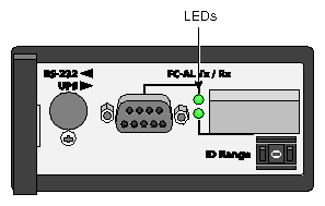
Two LEDs between the DB-9 connectors on the I/O panel light steady green to indicate a good FC-AL signal on the cables attached to the adjacent connectors. Figure 8-22 shows the LEDs on the I/O module panel.
If the LED for a connector is amber, check the connection. If the problem persists, contact your service provider for a replacement.
Each disk drive module has two LEDs, an upper (green) and a lower (amber), as shown in Figure 8-23.
The LEDs on the disk drive modules provide the information summarized in Table 8-3.
Table 8-3. Disk Drive LED Function
Green LED (Upper) | Amber LED (Lower) | State | Solution |
|---|---|---|---|
Off | Off | No disk drive fitted; that is, the drive is not fully seated. | Check that the drive is fully seated. |
On | Off | Disk drive power is on, but the drive is not active. | N/A |
Blinking | Off | Disk drive is active (LED might be off during power-on). | N/A |
Flashing at 2-second intervals | On | Disk drive fault (SES function). | Contact your service provider for a replacement drive and follow instructions in “Adding and Removing Disk Drive Modules” . |
N/A | Flashing at half-second intervals | Disk drive identify (SES function). | N/A |
In addition, the amber drive LED on the ESI/ops panel alternates between on and off every 10 seconds when a drive fault is present.
The ESI/ops panel includes an audible alarm that indicates when a fault state is present. The following conditions activate the audible alarm:
Drive fault
Fan slows down
Voltage out of range
Over temperature
Thermal overrun
Storage system fault
You can mute the audible alarm by pressing the alarm mute button for about a second, until you hear a double beep. The mute button is beneath the indicators on the ESI/ops panel (see Figure 8-20).
When the alarm is muted, it continues to sound with short intermittent beeps to indicate that a problem still exists. It is silenced when all problems are cleared.
| Note: If a new fault condition is detected, the alarm mute is disabled. |
This section explains D–brick temperature conditions and problems in these subsections:
The D–brick uses extensive thermal monitoring and ensures that component temperatures are kept low and acoustic noise is minimized. Airflow is from front to rear of the D–brick.
If the ambient air is cool (below 25 ˚C or 77 ˚F) and you can hear that the fans have sped up by their noise level and tone, then some restriction on airflow might be raising the D–brick's internal temperature. The first stage in the thermal control process is for the fans to automatically increase in speed when a thermal threshold is reached. This might be a normal reaction to higher ambient temperatures in the local environment. The thermal threshold changes according to the number of drives and power supplies fitted.
If fans are speeding up, follow these steps:
Check that there is clear, uninterrupted airflow at the front and rear of the D–brick.
Check for restrictions due to dust buildup; clean as appropriate.
Check for excessive recirculation of heated air from the rear of the D–brick to the front.
Check that all blank plates and disk–drive fillers are in place.
Reduce the ambient temperature.
The thermal alarm is a combination of all these:
Alarm sounds.
Power supply/cooling LED on the ESI/ops panel is amber.
LED on one or both power supply/cooling modules is amber.
Air temperature of the air exiting the PSU is above 55 ˚C (131 ˚F).
This alarm sounds when the internal temperature (measured in the airflow through the D–brick) exceeds a threshold. Follow these steps:
Check that local ambient environment temperature is below the upper temperature specification of 40 ˚C (104 ˚F).
Check that there is clear, uninterrupted airflow at the front and rear of the D–brick.
Check for restrictions due to dust buildup; clean as appropriate.
Check for excessive recirculation of heated air from the rear to the front.
The D–brick automatically shuts down to protect itself and the disk drives from damage. Thermal shutdown occurs under these conditions:
The D–brick shuts down ten seconds after any of these conditions is present.
When a thermal shutdown is imminent, all amber LEDs on the ESI/ops panel and on all disk drives flash and the alarm sounds continuously and cannot be muted.
When thermal shutdown conditions are present, follow these steps (if possible):
Check for airflow restrictions.
Check for power supply/cooling module faults as detailed in “Solving Power Supply/Cooling Problems”.
Check for excessive ambient temperatures (over 40 ˚C [104 ˚F])
If the overheating problem is not solved, thermal shutdown occurs. The standby LED on the ESI/ops panel and the power supply status LED are amber and the D–brick powers itself off.
Follow these steps:
Correct the source of the overheating.
Allow the D–brick to cool down.
Unplug the power cord from the D–brick and leave it unplugged for at least 30 seconds to reset the shutdown condition.
Reconnect the power cord and restart the D–brick, following the normal procedure (see “Powering the D–brick On or Off”).
Check for cooling faults that persist, particularly fan failure. If a fan has failed, contact your service provider for a replacement.
When no faults are present in the D–brick, you can run test mode to check the LEDs and the audible alarm on the ESI/ops panel. In this mode, the amber and green LEDs on each of the drive carrier modules and the ESI/ops panel flash on and off in sequence; the alarm beeps twice when test mode is entered and exited.
To activate test mode, press the alarm mute button until you hear a double beep. The LEDs then flash until the D–brick is reset, either when you press the alarm mute button again or if an actual fault occurs.
