This chapter describes how to remove and replace internal components of an Origin200 and Origin200 GIGAchannel server:
These tools are required to service parts inside the Origin200 and Origin200 GIGAchannel server:
#2 Phillips screwdriver (for all screws except on the blower assembly)
#1 Phillips screwdriver (for screws on the blower assembly)
needle-nose pliers or large tweezers (needed when servicing the CPU module fans, which are attached with plastic rivets)
small, flat-blade screwdriver
The following miscellaneous fasteners are used in the Origin200 and Origin200 GIGAchannel servers, in case you need to replace them:
plastic rivets to attach CPU module fans to the fan bulkhead; spare rivets are included with replacement fans from SGI
Phillips screws, 6-32 x 1/4-inch, for internal components and attaching rack ears to a rackmount system
Phillips screws, 10-32 x 1/2-inch, for attaching a rackmount system to an equipment rack
washers, #10 (.203 ID x .562 OD x .040 inch thick), for use with 10-32 x 1/2-inch screws in rackmounting
This section describes how to remove and install the following internal parts of the Origin200 and Origin200 GIGAchannel CPU module:
SCSI backplane
fans
logic carrier
power supply
system controller
Procedures to remove and replace the following components are described in other chapters in this guide:
PCI and XIO boards are described in Chapter 2, “Installing and Removing PCI and XIO Option Boards.”
Memory is described in Chapter 3, “Installing and Removing Memory.”
The 3.5-inch and 5.25-inch drives are described in the Origin200 and Origin200 GIGAchannel Owner's Guide.
If you have not done so already, follow the procedures in Chapter 1, “Preparing the System for Servicing” to make sure the system is opened up and ready to be worked on. Once you have opened the Origin200 chassis, follow the procedures in the next sections to remove the SCSI backplane and install a new one.
Follow these steps to remove the SCSI backplane:
Remove any 3.5-inch drives from the drive bays.
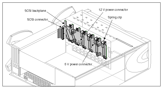
Detach the power cables from the SCSI backplane.
Figure 5-1 shows the location of the 12V and 5V power connectors.
If you are able, detach the SCSI cable from its connector; otherwise, wait until the backplane is partway out of the chassis.
Snap down the six spring clips on the SCSI backplane. The spring clips are shown in Figure 5-1.
Grasp the SCSI backplane by the edges and tilt it out. The backplane hangs on two pins; pull the backplane up off the pins.
With the board partway out of the chassis, unhook the SCSI cable on one end of the SCSI backplane, if you have not already done so. Remove the backplane from the chassis and set it aside.
Follow these steps to install a new SCSI backplane:
Hang the new SCSI backplane over the guide pins on the sheetmetal wall (the one towards the front of the chassis).
As you lower the board in place, gently press in at the bottom of the board.
Push the top of the SCSI backplane towards the sheetmetal wall, being careful not to damage the LEDs as you guide them through their respective holes.
Snap the six spring clips back up into place.
Reattach the power cables.
If you have not done so already, follow the procedures in Chapter 1, “Preparing the System for Servicing” to make sure the system is opened up and ready to be worked on. Once you have opened the Origin200 chassis, follow the procedures in the next sections to replace a fan.
Follow these steps to remove a fan:
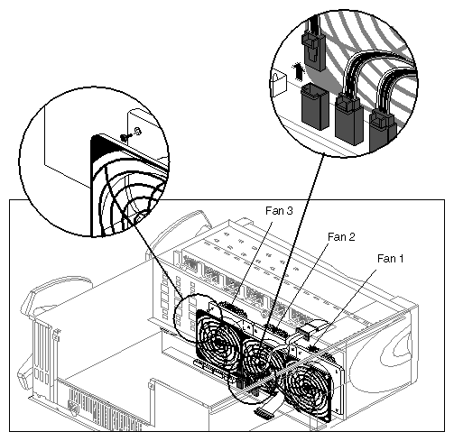
Unplug the power connector from the fan to the power supply, as shown in Figure 5-2.
Remove the two plastic rivets that hold the fan to the sheetmetal, as shown in Figure 5-2. Push them out from behind the sheetmetal with your fingertip.
Fan 1 is directly behind the 5.25-inch drive bay.
Fan 2 is in the middle, between fans 1 and 3.
Fan 3 is closest to the PCI backplane.
In Figure 5-2, components in front of the fans (including the power supply and logic carrier) have been removed for clarity. In practice, you can remove and replace fans with the power supply and logic carrier in place.
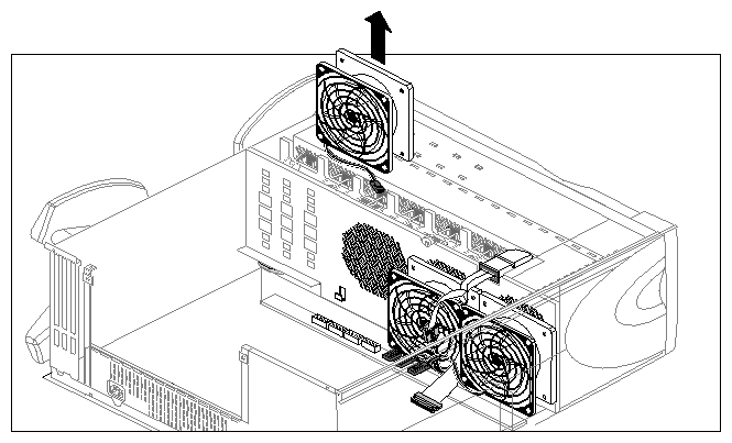
Lift the fan out of the system, as shown in Figure 5-3.
Follow these steps to install a fan:
Lower the new fan into the system, resting the lip of the fan on the sheetmetal catches.
Snap a plastic rivet in the top corners of the fan to secure it to the sheetmetal. The rivet has two parts: a sleeve and a pin.
Place the pin partway inside the sleeve, then slide both through the hole in the fan.
Press the pin and sleeve together towards the sheetmetal. The pin and sleeve slide into place with the ends of both protruding through the sheetmetal.
If you have large hands or fingers, you may find it easier to handle the rivets with needle-nose pliers or large tweezers.
If you have not done so already, follow the procedures in Chapter 1, “Preparing the System for Servicing” to make sure the system is opened up and ready to be worked on. Once you have opened the Origin200 chassis, follow the procedures in the next sections to replace the logic carrier.
If there are any PCI boards in the system, remove them as described in Chapter 2, “Installing and Removing PCI and XIO Option Boards.”
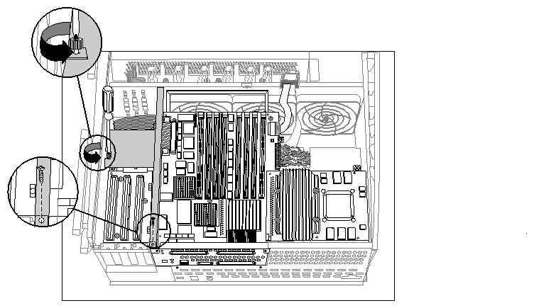
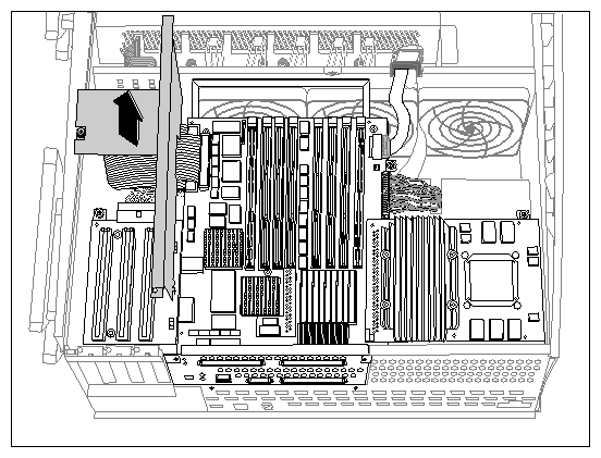
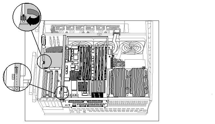
Using a #2 Phillips screwdriver, remove the sheetmetal screw and captive fastener that secure the PCI plenum divider and lift the divider out of the system. See Figure 5-4.
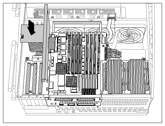
Lift the PCI plenum divider sheetmetal out of the system, as shown in Figure 5-5.
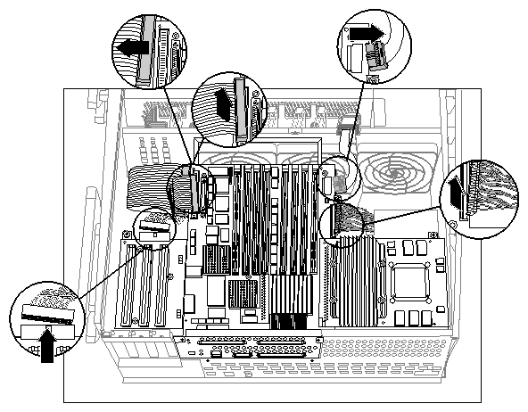
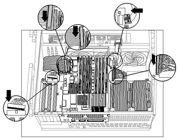
Disconnect the cables that are attached to the logic carrier, as shown in Figure 5-6.
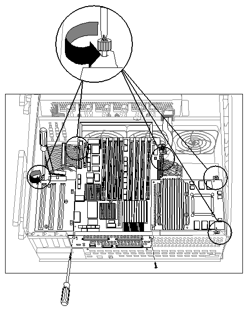
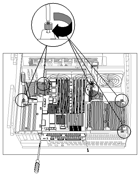
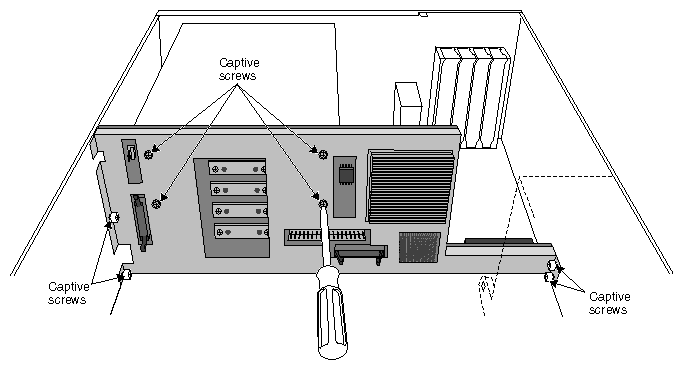
Unfasten the captive screws and sheetmetal screws that secure the logic carrier. See Figure 5-7.
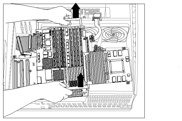
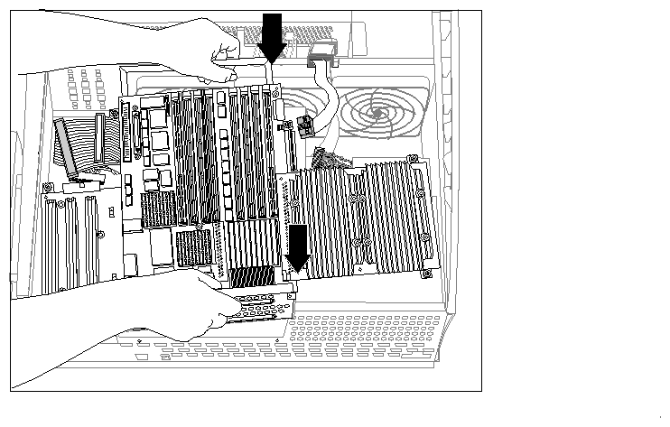
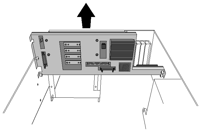
Lift the logic carrier out of the system, as shown in Figure 5-8.
Grasp the logic carrier handle with one hand and the connector panel with the other.
As you lift the logic carrier, tilt the side with the CPU daughtercard up slightly higher than the side with the PCI backplane. Angling the logic carrier in this way makes it easier to remove.
Follow these steps to replace the logic carrier:
Lower the new logic carrier into the system, as shown in Figure 5-9.
Secure the logic carrier by tightening the captive fasteners and installing the sheetmetal screws, as shown in Figure 5-10.
Attach the PCI power, SCSI controller, system controller, and system board power cables to the logic carrier, as shown in Figure 5-11.
Install the PCI plenum divider sheetmetal as shown in Figure 5-13.
Fasten the PCI plenum divider by tightening the captive screw and installing the sheetmetal screw, as shown in Figure 5-13.
You are finished replacing the logic carrier. You can now reinstall any PCI option boards that were present in the system, and return the system to working order.
If you have not done so already, follow the procedures in Chapter 1, “Preparing the System for Servicing” to make sure the system is opened up and ready to be worked on. The procedure is identical for replacing the standard and redundant power supplies.
| Note: Be aware that the redundant power supply works only in systems with module system controller firmware versions 3.3S and later. See the Origin200 and Origin200 GIGAchannel Owner's Guide for details on determining the MSC version number. |
Once you have opened the Origin200 chassis, follow the steps in the next sections to replace the power supply.
Follow these steps to remove the Origin200 power supply:
Remove any PCI boards that are in the system, as described in Chapter 2, “Installing and Removing PCI and XIO Option Boards.”
Remove the logic carrier as described in “Replacing the Logic Carrier”.
Disconnect all cables from the power supply: fan power, the combined SCSI backplane and 5.25-inch drive power connector, and module system controller cable.
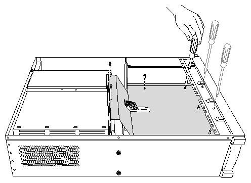
Using a #2 Phillips screwdriver, remove the screws that secure the power supply to the chassis, as shown in Figure 5-14. There are six screws at the rear of the power supply.
Remove the power supply, as shown in Figure 5-15.
Follow these steps to install a new power supply in an Origin200 server:
Redundant power supply only: Remove the fans from the chassis.
See “Replacing Fans” for information on removing the fans.
Because the redundant power supply is slightly longer than the standard power supply, removing the fans gives you necessary additional room in which to work.
Lower the power supply into the chassis with the power switch and receptacle towards the rear of the system.
Slide the power supply back until it latches on the underside and the power switch and receptacle are flush with the back of the chassis.
Install the screws at the rear of the system, as shown in Figure 5-16. Six screws secure the power supply to the chassis.
Reconnect some of the cables: fan power cables, SCSI drive power cable, module system controller cable.
Install the logic carrier and any PCI boards you removed.
Reconnect the logic carrier cables.
Replace the chassis access cover.
If the system is in a tower configuration, replace both side panels.
| Note: For this procedure, you do not have to follow the instructions in Chapter 1, “Preparing the System for Servicing.” The module system controller can be removed with the system in place and fully assembled. However, make sure you turn off the master power switch. |
The module system controller (MSC) is mounted on a sheetmetal carrier to form a single assembly. This assembly is housed behind the plastic bezel crossbar that forms the system front panel (where the status LED is located). Follow the steps in the next sections to remove the MSC and replace it.
Follow these steps to remove the module system controller (MSC):
Shut down the system and turn off the master power switch.
Open the front door.
Remove the front bezel crossbar.
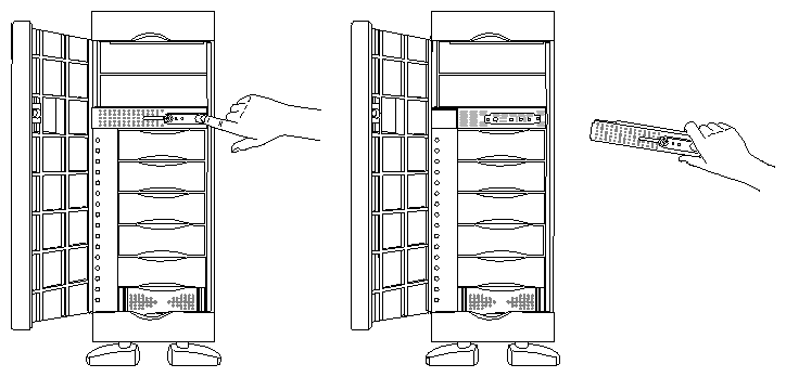
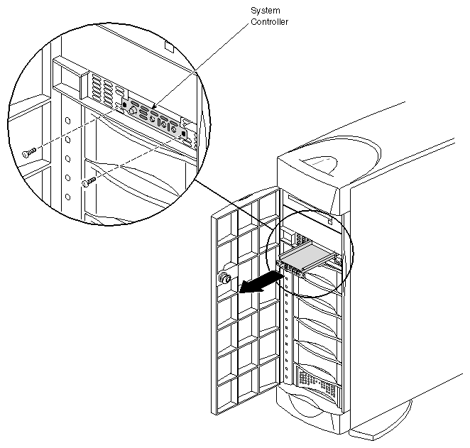
With your index finger, press against the catch on the inside of the recess in the crossbar, on the outside (right or top) of the recess. This recess is where the door lock fits. See Figure 5-17.
The crossbar swings out, hinging on the far side from the catch. Pull the crossbar out and set it aside.
Using a #2 Phillips screwdriver, remove the two screws that fasten the system controller assembly to the chassis, as shown in Figure 5-18.
Pull out the system controller assembly and lay it on a flat surface.

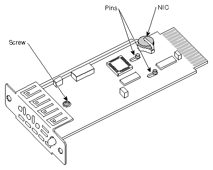
Caution: To prevent ESD damage to the module system controller, be careful not to touch the board's edge connectors (gold fingers). Remove the system controller board from its carrier; it is secured by a screw and two pins, as shown in Figure 5-19.
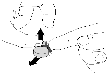
Remove the NIC (number in a can) package from the controller board. The NIC is a silver-colored device located at the rear of the controller board. It looks like a very large watch battery. See Figure 5-20.
Follow these steps to attach a new module system controller board to the sheetmetal carrier and install it in the system:
Install the NIC from the original module system controller on the replacement controller board.
Position the replacement controller board over the pins in the carrier; grasping the board by its sides, slide it so that the pins lock, making sure that the LED and button go through the proper holes. Screw in the reserved screw (shown in Figure 5-19).
Remove the disks (or blanking plates if no disks are installed) from slots 5 and 6 of the Origin200 server. Removing the disks (or blanking plates) allows you to see how the edge connector on the module system controller board aligns with its socket inside the chassis.
Slide the system controller assembly into the chassis. The assembly installs in only one direction.
If necessary, guide the edge connector into its socket.
When the edge connector is fully seated, the front of the carrier assembly should be flush with the chassis.

Caution: To prevent ESD damage to the module system controller, be careful not to touch the board's edge connectors (gold fingers). Replace the disks or blanking plates you removed in step 3.
Replace the two Phillips screws that hold the MSC assembly in place.
Replace the front bezel crossbar.
This section describes how to replace the various internal parts of the GIGAchannel expansion cabinet.
If you have not done so already, follow the procedures in Chapter 1, “Preparing the System for Servicing.” to make sure the system is opened up and ready to be worked on. Once you have opened the GIGAchannel chassis, follow the procedures in the next sections replace the blower.
Remove the six screws that secure the power supply shroud, as shown in Figure 5-21.
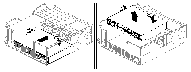
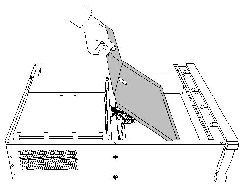
Lift the power supply shroud out of the chassis, as shown in Figure 5-22.
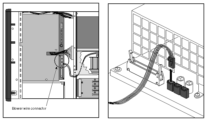
Unplug the power connector for the blower.
To unplug the connector, press the latch on the connector and lift it out of the socket, as shown in Figure 5-23.
The fan-power connectors on the redundant power supply are oriented slightly differently from those on the standard power supply, but are otherwise identical. The blower is attached to the connector that would be used by fan 1 if the power supply were installed in a CPU module.
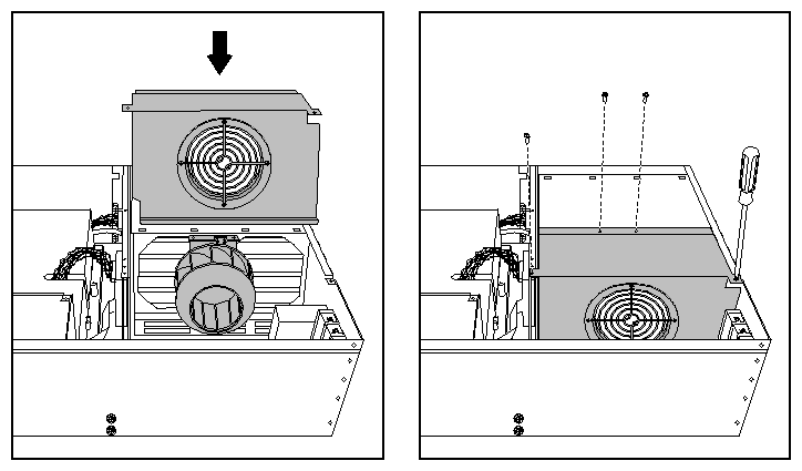
Remove the blower cover.
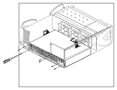
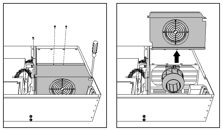
Remove the four screws that attach the blower cover to the XIO cardcage, as shown in Figure 5-24.
Lift the blower cover out of the chassis.
Remove the blower assembly.
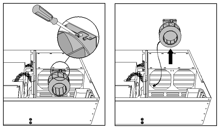
You may find that a smaller screwdriver, such as a #1 Phillips, or an offset screwdriver is easier to use than a #2 Phillips screwdriver.
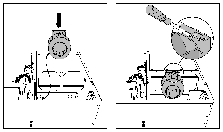
The best way to undo the captive fasteners with a straight-shank screwdriver is to hold the screwdriver at an angle (as shown in Figure 5-25), and carefully turn the captive screws in small increments, counterclockwise.
Lift the entire blower assembly out of the GIGAchannel, as shown in Figure 5-25.
To install a blower, follow these steps:
Replace the blower assembly, as shown in Figure 5-26.
Lower the blower into place.
Tighten the captive screws. The best way to tighten the captive fasteners with a straight-shank screwdriver is to hold the screwdriver at an angle (as shown in Figure 5-26), and carefully turn the captive screws in small increments, clockwise.
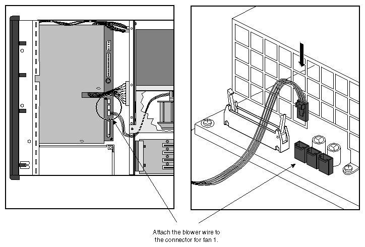
Reattach the blower power cable, as shown in Figure 5-27.
The fan-power connectors on the redundant power supply are oriented slightly differently from those on the standard power supply, but are otherwise identical. Attach the blower wire to the connector that would be used by fan 1 if the power supply were installed in a CPU module.
Replace the blower cover, as shown in Figure 5-28.
Replace the power supply shroud, reversing steps 1 and 2 on page 99 and page 100.
If you have not done so already, follow the procedures in Chapter 1, “Preparing the System for Servicing” to make sure the system is opened up and ready to be worked on. The procedure is identical for replacing the standard and redundant power supply.
| Note: Be aware that the redundant power supply works only in systems with module system controller (MSC) firmware versions 3.3S and later. See the Origin200 and Origin200 GIGAchannel Owner's Guide for information about determining the MSC version number. |
Once you have opened the GIGAchannel chassis, follow the procedures in the next sections to replace the power supply.
Remove the power supply shroud.
Remove the four sheetmetal screws indicated in Figure 5-29.
Undo the two captive screws indicated in Figure 5-29.
Lift the shroud up and out of the chassis.
As you lift the shroud, tilt it as shown in Figure 5-30.
Disconnect all of the wires attached to the power supply.
Pull the power supply towards you until it unlatches from the base of the chassis.
Lift the power supply up and out of the system.
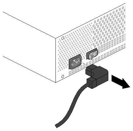
Disconnect the power cord extension at the front of the power supply, as shown in Figure 5-31.
Follow these steps to install a new power supply:
Attach the power cord extension to the front of the power supply, next to its built-in rocker switch.

Note: There is a metal standoff located inside the chassis on the front bulkhead that presses on the rocker switch when the power supply is installed. Even if you forget to turn on the built-in rocker switch, this standoff will push the switch into the correct position. Lower the power supply into the chassis and slide it forward until you feel the latches connect.
If the power supply is correctly installed, you should not be able to lift it straight up and out of the chassis.
Reconnect the wires you removed.
Attach the blower wire to connector 1 (farthest away from the blower). See Figure 5-27.
Replace the latching logic connector (ribbon cable). It is keyed and can be installed in only one direction. Press down on the connector until the tabs on each side of the connector are fully engaged.
Replace the white power connector (braided pairs of wire). It is keyed and can be installed in only one direction.
Replace the shroud, reversing the steps on page 108 through page 109.
Pay close attention to the alignment of the holes in the shroud and the holes in the power supply. If they do not line up, you may have to shift the power supply slightly to the right, or slightly farther back towards the midplane.
Attach the captive screws, then install the four sheetmetal screws indicated in Figure 5-29.
Reassemble the system (replace covers, reattach cables, and so forth).
The steps in the following sections describe how to remove and replace the PCI backplane in the GIGAchannel expansion cabinet.
Follow these steps to remove the PCI backplane:
Follow the procedures described in Chapter 1, “Preparing the System for Servicing” to shut down the system and remove the necessary covers from the chassis.
Remove any PCI boards that are currently installed, as described in Chapter 2, “Installing and Removing PCI and XIO Option Boards.”
Remove the backplane.
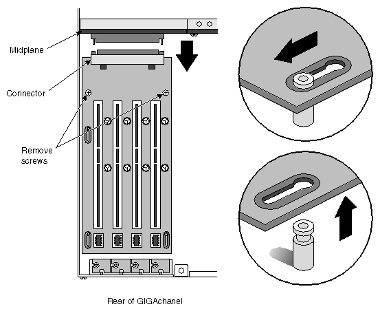
Remove the two screws, indicated in Figure 5-32.
Slide the PCI backplane towards the rear of the system so that its connector releases from the midplane.
Lift the board off of the retaining pins and out of the system.
Follow these steps to install a new GIGAchannel PCI backplane.
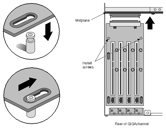
Lower the PCI backplane over the top of the retaining pins.
Secure the backplane.
Slide the backplane backwards until the connector on the PCI backplane fully engages the mating connector on the midplane, as shown in Figure 5-33.
Replace the two screws indicated in Figure 5-33.
Replace any PCI boards that were removed.
Reassemble the system (replace covers, reattach cables, and so forth).
The next sections describe how to replace the GIGAchannel midplane.
Follow these steps to replace the midplane:
Follow the procedures described in Chapter 1, “Preparing the System for Servicing,” to shut down the system and remove the necessary covers from the chassis.
Remove the PCI backplane. See “Replacing the GIGAchannel PCI Backplane”.
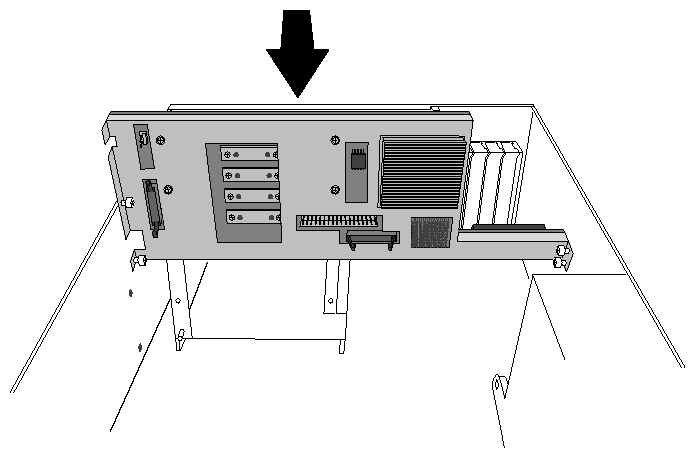
Remove the blower cover, as shown in Figure 5-34.
Remove the power-supply shroud screws, as shown in Figure 5-35.
Remove the power supply shroud, as shown in Figure 5-36.
Disconnect all wires attached to the midplane.
Undo the eight captive screws that hold the midplane in place, as shown in Figure 5-37.
Lift the midplane up and out of the chassis, as shown in Figure 5-38.
You are finished removing the midplane.
Follow these steps to install a new midplane.
Lower the new midplane into the GIGAchannel chassis, as shown in Figure 5-39.
Tighten the captive screws indicated in Figure 5-40.
Reconnect all midplane wires (including blower and power supply).
Replace the power supply shroud.
Replace the blower cover.
Replace the PCI backplane.
Reassemble the system (replace covers, reattach cables, and so forth).
You are finished replacing the midplane.
The next sections describe how to replace the GIGAchannel Crosstown board.
| Note: Depending upon how your GIGAchannel cabinet is installed, you may not have to follow the procedures in Chapter 1, “Preparing the System for Servicing” to replace the Crosstown board. The board can be removed and replaced with the system completely assembled (except for the XIO cables). However, if the server is mounted in an equipment rack, you may need to remove the GIGAchannel cabinet from the rack in order to gain access to the rear of the chassis. |
Follow these steps to remove the Crosstown board:
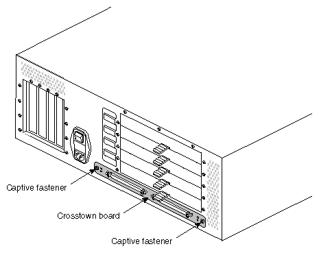
Remove the XIO cables that are attached to the Crosstown board.
Undo the two captive fasteners on the Cfcrosstown board, at the rear of the chassis. See Figure 5-41.
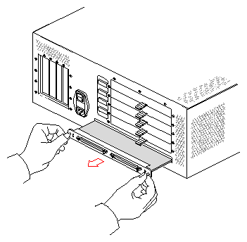
Pull the board out of the chassis, as shown in Figure 5-42. You may have to pry the board slightly using a small, flat-bladed screwdriver.

Caution: Be extremely careful not to damage the copper gasket in between the ears of the board (underneath the captive fasteners) and the chassis.
Follow these steps to install a new Crosstown board:
Slide the new board in place.
Note the alignment of the sides of the board on the guides inside the chassis. When properly aligned, the board should slide easily.
Slide the board back into chassis and press firmly to seat the connector at the back of the board.
Tighten the captive screws to secure the board.
Replace the XIO cables.
Connect XIO connectors A together on both the CPU module and the expansion cabinet.
Connect XIO connectors B together on both the CPU module and the expansion cabinet.
| Note: Depending upon how your GIGAchannel cabinet is installed, you may not have to follow the procedures in Chapter 1, “Preparing the System for Servicing,” to replace a fuse. The fuses can be removed and replaced with the system completely assembled (except for the power cable). However, if the server is mounted in an equipment rack, you may need to remove the GIGAchannel cabinet from the rack in order to gain access to the rear of the chassis. |
The fuses are located in the black power plug housing (where you attach the power cord). Follow these steps to replace a fuse:
Shut down the system and unplug the power cords from both the CPU module and the GIGAchannel expansion chassis.
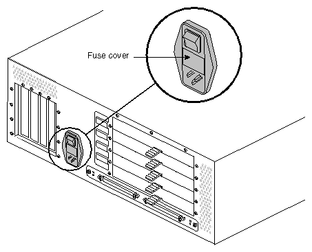
Locate the fuse cover on the GIGAchannel chassis, which is part of the power plug housing. See Figure 5-43.
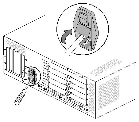
Insert a small, flat-blade screwdriver in the notch of the fuse cover and pry outward. The fuse cover should release. See Figure 5-44.
There are two fuses inside the fuse cover. Locate the blown fuse and replace it with an identical type.
Snap the fuse cover back in place.
