This chapter describes how to install and remove dual in-line memory modules (DIMMs) in an Origin200 CPU module:
Memory is extremely sensitive to electrostatic discharge (ESD). Observe the following precautions when installing and removing memory:
Handle the DIMMs by their edges only and do not touch the gold connector pads.
Handle DIMMs with care. Do not toss them roughly onto hard surfaces, such as tables or other equipment.
Do not leave DIMMs loose inside the chassis while you work.
When you are not handling DIMMs for installation or removal, always keep them in ESD containers, such as conductive bags or foam.
Save the ESD bags or containers in which the memory option was shipped in case you need to remove the DIMMs from the system.
Observe these rules about installing DIMMs:
DIMMs must be installed in pairs.
Each DIMM of a pair must be the same size (for example, 32 MB, 64 MB, and so on).
You can mix memory sizes between banks. In other words, bank 1 can have a pair of 32 MB DIMMs while bank 2 has a pair of 64 MB DIMMs and bank 3 has another pair of 32 MB DIMMs.
Each module must have memory installed (32 MB minimum per module)
Follow these steps to install memory in an Origin200 server:
Prepare the system for servicing as described in Chapter 1, “Preparing the System for Servicing.”
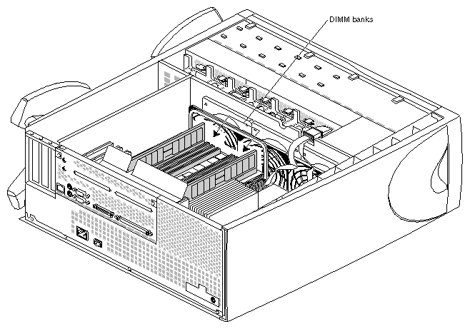
Locate the DIMM slots. See Figure 3-1.
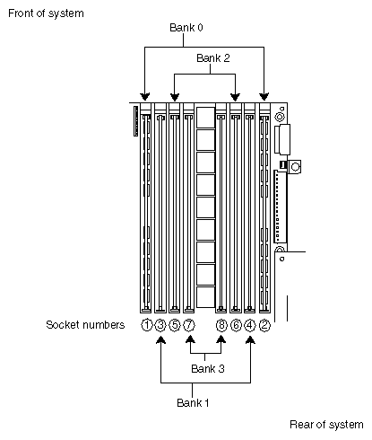
Install DIMMs in pairs, starting with the pair farthest away from the center of the banks and working inward. Do not skip banks. Figure 3-2 shows the grouping of DIMM pairs:
Figure 3-2 shows one pair of DIMMs installed in bank 0 (all modules must have memory in bank 0; if you have a two-module system, both must have memory in bank 0).
If you are installing one additional pair of DIMMs, install them in bank 1.
Install a third pair of DIMMs in bank 2.
Install a fourth pair of DIMMs in bank 3.
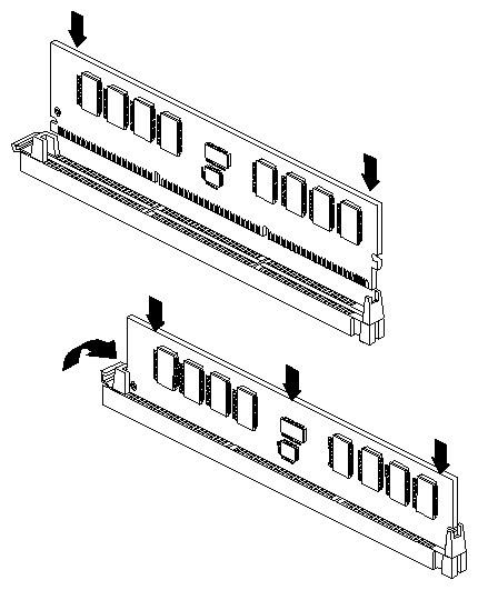
Figure 3-3 shows how to insert a DIMM into its socket.
As you lower the DIMM into its socket, press down first on one side then the other to seat the DIMM (upper drawing).
Press straight down across the entire top to make sure the DIMM is firmly seated. Avoid placing sideways pressure on the DIMM. The DIMM-release lever should move upward and towards the edge of the DIMM when it is completely seated (lower drawing).
After you have finished installing DIMMs, remove your wrist strap and reassemble the system.
Replace the chassis access door and side panel (the reverse of removing them).
Reattach the cables to the back of the system.
You are now ready to verify that the memory is recognized by the system.
After you have installed memory, you can verify that it is recognized by the system. Follow these steps:
Log in to the server (as root, guest, or any account you wish).
At a shell prompt, enter the following command:
hinv -t memory
You should see a message similar to this:
Main memory size: 128 Mbytes
If you originally had 64 MB of memory and you installed an additional 64 MB, hinv should report that the system has 128 MB of memory.
If hinv does not report the correct amount of memory, it may be because one or more of the DIMMs you installed is not seated correctly. Shut down the system and reseat the DIMMs.
Follow these steps to remove memory from an Origin200 server:
Prepare the system for servicing as described in Chapter 1, “Preparing the System for Servicing.”
Locate the DIMMs. See Figure 3-4.
Remove DIMMs in pairs, starting with the pair closest to the center of the banks (bank 3). See Figure 3-5.
Start by removing bank 3, then bank 2, then bank 1. Do not skip banks.
You must have memory installed in bank 0 of both modules in order for the system to operate. You cannot operate a two-module system unless there are DIMMs installed in both modules.
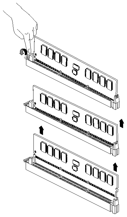
Figure 3-6 shows how to remove the DIMMs from their sockets.
Press down on the release lever for the DIMM you want to remove. The lever raises the DIMM out of that side of its socket.
Grasp the DIMM along the edges and pull it up out of its socket with an end-to-end rocking motion. (Avoid excess side-to-side motion, as this may damage the socket.)
After you have finished removing DIMMs, remove your wrist strap and reassemble the system.
Replace the chassis access door and side panel (the reverse of removing them).
Reattach the cables to the back of the system.


