This chapter describes how to prepare Origin200 and Origin200 GIGAchannel servers for installing and removing internal parts, including PCI options, memory, fans, and other components. This chapter contains the following sections:
Follow these steps to shut down the system:
Log in to the system as root.
Verify that no one is using the system, or that it is not in the middle of a critical task.
At a shell prompt, enter this command:
/etc/shutdown -g0
This begins to shut down the system immediately. See the shutdown(1M) reference page for more information.
You see various messages about the system shutting down, then you see the System Maintenance Menu:
Running power-on diagnostics...
System Maintenance Menu
1) Start System
2) Install Software
3) Run Diagnostics
4) Recover System
5) Enter Command Monitor
   Option?
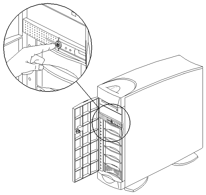
Once you see the System Maintenance Menu, locate the power button at the front of the chassis (the master chassis in a two-module system) and press it once. See Figure 1-1.If you are going to move the system, wait a few more seconds to allow the internal disks to stop spinning.
In an Origin200 GIGAchannel server, the front power switch also turns off the GIGAchannel expansion cabinet.
If you are installing or removing only XIO option boards in a GIGAchannel expansion cabinet, you do not need to do anything more to the system. Turn to Chapter 2, “Installing and Removing PCI and XIO Option Boards.”
The status LED on the front of the system blinks, then goes out when the system is powered off.
If you are installing PCI options or memory or are servicing internal components, disconnect all cables from the rear of the chassis, including serial, Ethernet, CrayLink Interconnect, XIO, grounding, power, and so forth.
If the system is in an equipment rack and you are installing PCI options or memory, or you are servicing internal components, proceed with the next section, “Removing the System From a Rack (Rackmount Only)”.
If the system is in a tower configuration and you are installing PCI options or memory, or are servicing internal components, skip to the section “Removing the System Cover (Tower Only)”.
Follow these steps to remove the system from an equipment rack:
If you are servicing a CPU module, you may wish to either lock the front door closed or remove it from the server. This step is optional.
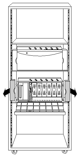
Remove the plastic end caps, as shown in Figure 1-2.
Remove the screws that secure the chassis to the equipment rack.
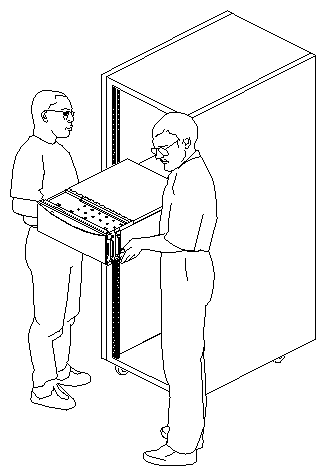
With two people, one standing on each side of the chassis, slide the chassis out of the rack, as shown in Figure 1-3.
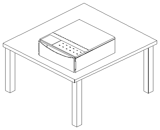
Place the chassis on a sturdy work surface, as shown in Figure 1-4.
You are now ready to remove the chassis access cover. Proceed to “Removing the Chassis Access Cover”.
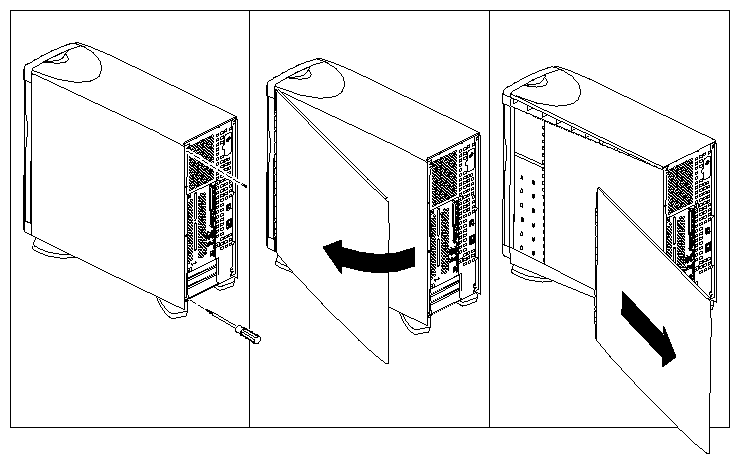
To remove the system cover, follow these steps:
Using a #2 Phillips screwdriver, remove the two screws that secure the system cover to the chassis. See Figure 1-5.
Pull the rear edge of the cover away from the rear of the system.
Slide the system cover back and off the system, as shown in Figure 1-5.
You are now ready to remove the chassis access cover.
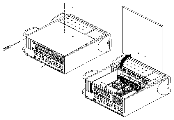
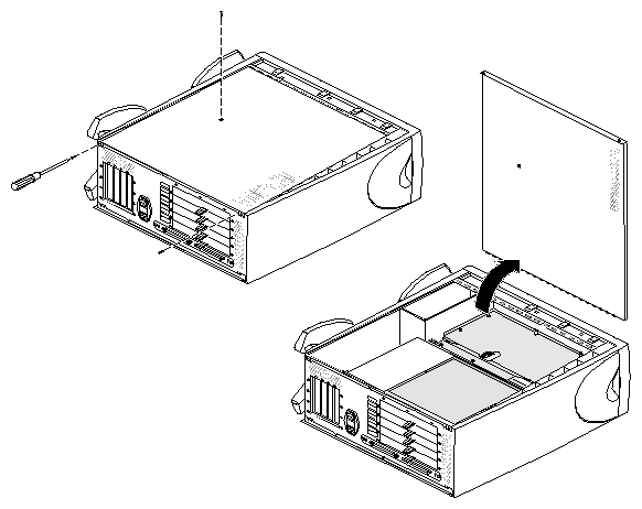
The chassis access covers on the CPU module and GIGAchannel are almost identical, except that there are two screws on the face of the cover of the CPU module (shown in Figure 1-6) and only one screw on the face of the cover of the GIGAchannel expansion cabinet (shown in Figure 1-7).
Figure 1-6 shows how to remove the chassis access cover from a CPU module.
Figure 1-7 shows how to remove the chassis access cover from a GIGAchannel expansion cabinet.
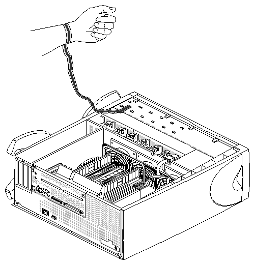
| Warning: Whenever you work on internal components, always use a grounding (wrist) strap to prevent the flow of potentially damaging static electricity. |
Attach one end of a grounding strap to your wrist and the other to a metal portion of the chassis, as shown in Figure 1-8. Grounding straps are typically included with memory, PCI, and XIO options.
You are now finished preparing the system for servicing.
