This chapter tells you how to install
a second internal SCSI drive (floptical or hard disk); see “Installing an Internal Floptical Drive or Second Hard Disk”
external SCSI devices; see “Installing External SCSI Devices”
serial devices; see “Installing the System Console and Other Serial Devices”
| Note: If you need to install the system disk (the disk with the IRIX operating system installed on it), follow the instructions in “Replacing the System Drive”. If you are connecting a system disk that does not yet have the IRIX operating system installed on it, you need to go through a specific software procedure to format the disk, create partitions on the disk, then install the IRIX operating system on the system disk. See the Software Installation Administrator's Guide for information on installing IRIX on a new system disk. |
This section tells you how to install a second internal drive, such as a floptical or second hard disk, in the top drive slot of the Challenge S server.
The system disk drive should always be installed in the bottom slot.
Use these instructions to install either a floptical or a second hard disk drive.
Follow these steps to power off the system, remove the top cover, remove the empty drive bracket (or installed drive) from the top drive slot, connect the cables, install the drive, and replace the top cover.
If the system is powered on, press and release the power button on the front panel to power off the system.
The system powers off automatically after about a minute.
Disconnect the power cable from the back of the Challenge S server.
Remove the top cover by releasing the latch on the rear of the cover and sliding it forward. For more details, see “Removing the Top Cover”.
Ground yourself to a metal part of the server chassis.

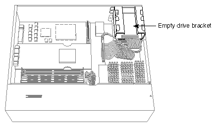
Caution: Drives can be easily damaged. Handle your drive carefully. Do not drop it or otherwise abuse it. Move the system or position yourself so that the power supply is close to you and the system drive and empty drive bracket are in the upper right-hand corner, as shown in Figure 6-1.
If a drive is already installed in the upper drive slot and you wish to remove it, go to “Replacing the Internal Floptical Drive or Second Hard Disk Drive”.
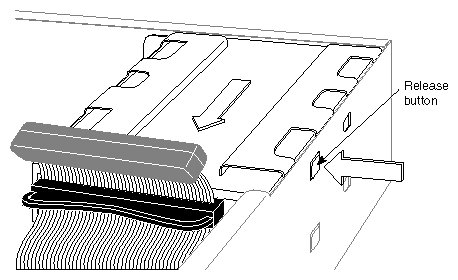
Remove the empty drive bracket (with the face plate attached) by pressing the release button that protrudes through the side of the chassis and pulling the bracket toward you, as shown in Figure 6-2.
Figure 6-2 shows how to remove the upper drive bracket, but the procedures for removing both upper and lower drive brackets are the same. Save the drive bracket and face plate. If you remove the drive and do not replace it, you must reinstall them.
Caution: The empty drive bracket provides support for any monitor or terminal that sits on top of the system. Do not remove it unless you are installing a drive in the top slot. If you are installing a floptical drive, refer to Appendix C to check the drive's jumper settings.
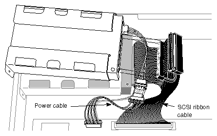
Connect an unused power cable to the drive. A floptical drive will have an adapter cable attached to it, as shown in Figure 6-3. For a second disk drive, attach the power cable directly to the receptacle on the drive.
Install the drive and attach the SCSI cable.
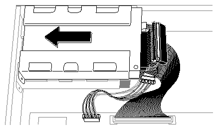
Position the drive and bracket over the system disk.
Slide the metal tabs underneath the bracket into the holes on the top of the system drive's bracket. At the same time, make sure that the button on the right side of the bracket snaps into the hole on the side of the chassis.
Attach the SCSI cable to the drive. For both the floptical and a second hard drive, use the connector at the end of the cable. Press it firmly against the connector on the drive and make sure it is seated.
If you have no more internal options to install, replace the top cover by inserting the tab through the hole in the rear of the chassis and sliding the cover back until it snaps into place. For more information, see “Replacing the Top Cover”.
Reconnect the power cable to the connector on the back of the Challenge S server.
Press and release the power button on the front panel to power on the system.
When you see the System Maintenance menu, you are ready to test the drive you installed. Go to the next section, “Testing the Internal Drive”.
Follow these steps to check that the system recognizes the new drive.
At the System Maintenance menu, select option 5 to enter the Command Monitor.
At the Command Monitor prompt (>>), enter the following command:
hinv
The hinv command provides a list that looks similar to the following:
1 200 MHZ IP22 Processor
FPU: MIPS R4010 Floating Point Chip Revision: 0.0
CPU: MIPS R4400 Processor Chip Revision: 6.0
On-board serial ports: 2
On-board bi-directional parallel port
Data cache size: 16 Kbytes
Instruction cache size: 16 Kbytes
Secondary unified instruction/data cache size: 1 Mbyte
Main memory size: 64 Mbytes
Integral ISDN: Basic Rate Interface unit 0, revision 1.0
Integral Ethernet: ec3, version 1
Integral Ethernet: ec0, version 1
Integral SCSI controller 5: Version WD33C95A, differential, revision 0
Integral SCSI controller 4: Version WD33C95A, differential, revision 0
Integral SCSI controller 0: Version WD33C93B, revision D
Disk drive: unit 1 on SCSI controller 0
Disk drive: /removable media: unit 2 on SCSI controller 0
If you have more than one hard disk drive, you'll see multiple disk drive listings, each with a different controller unit number combination. The system disk is always unit 1. Make sure the drive appears in the hinv listing. If it doesn't, it may not be properly connected and configured. To check, power off the system and check the power and SCSI connections and ID. Then restart the system and check the drive installation with hinv again.
You are finished installing the floptical or second hard disk drive.
The floptical drive can read from and write to both optical floppy diskettes and standard, 3.5” diskettes. Before you can use diskette with IRIX, you must format it. There are two ways to format a diskette, depending upon how you want to use the disk:
This applies whether you are going to back up files using tar and cpio, use the diskette as a mounted filesystem, or use it to store MS-DOS or Macintosh format files. However, if you format a diskette as an IRIX filesystem, you cannot use it with the MS-DOS emulation software SoftPC/AT, or use the diskette on a non IRIX (non UNIX®) system.
To the floptical diskette as an IRIX filesystem, follow these steps to format a floppy:
At an IRIX shell prompt, enter:
fx -x “fd(0,unit_number)”
In this command, unit_number is the SCSI unit number (address) of the device. For example, 2.
You see this message:
Which floppy type (one of 48, 96, 96hi, 480, 3.5, 3.5hi, or 3.5.20m)[96]
Enter the number for the type of disk that you are formatting. For a 3-1/2” (21MB) diskette, type:
3.5.20m
Press <Enter>.
At the fx> prompt, enter
format
The system asks you:
About to destroy data on fd(0,2)! ok?
Enter
yes
When the prompt returns, enter
exit
The disk begins formatting. It can take as long as 20 minutes to format a 20 MB capacity optical diskette.
You are finished formatting the floptical diskette as an IRIX filesystem. You can mount the floptical diskette as you would mount any other filesystem. See mount(1M) and fx(1M) for more information.
To format the floptical as an MS-DOS or Macintosh diskette, follow these steps:
Insert the floptical diskette in the floptical drive.
Use the mkfp command to format the floptical diskette:
mkfp -t type -x /dev/rdsk/fds0d1.3.5 volume_label
To format a Macintosh floptical with a volume label of “My-disk”:
mkfp -t mac -x /dev/rdsk/fds0d1.3.5 My-disk
To format an MS-DOS floptical with a volume name of “My-DOS-disk”:
mkfp -t dos -x /dev/rdsk/fds0d1.3.5 My-DOS-disk
The volume label is optional. The –x option formats the disk.
The instructions above describe how to format a diskette as high-density, 3.5” form-factor. Although you can format a 20 MB optical disk in both MS-DOS and Macintosh formats, not all MS-DOS and Macintosh systems are equipped with floptical drives and these may not be able to use a 20 MB optical disk.
You are finished formatting the floptical disk. For more information, see the mkfp(1), fpck(1), msdosd(1M), and smfd(7M) reference pages.
Under IRIX, you can use the floptical in the same way you use a tape. For example, you can back up files to the drive using tar or cpio. To use the floptical instead of the default device, specify the floptical device name in the command. All floptical devices are in /dev/dsk and /dev/rdsk.
This example copies all the files in the current directory to a 20 MB floptical diskette loaded in the floptical drive installed as SCSI unit 2 on controller 0:
tar cvf /dev/rdsk/fds0d2.3.5.20m * |
For a complete description of the floptical device files, see smfd(7M). For a complete description of the various tar and cpio options, see the tar(1) and cpio(1) reference pages. Also, for a discussion of backup commands, refer to the IRIX Advanced Site and System Administration Guide (for IRIX 5.3 systems) and IRIX Admin: Backup, Security, and Accounting (for IRIX 6.2 systems).
To eject a floptical diskette, use the eject command. Always make sure the system is not accessing the floptical when you attempt to eject it.
If the floptical drive is the only removable media device connected to the Challenge S server, you can eject the diskette by typing:
eject |
Since the eject command can eject either a floptical, a CD-ROM, or certain tapes, if you have more than just the floptical drive installed, you must specify which device you want to eject. For example, to eject a floptical diskette, enter the following command at the IRIX shell prompt:
eject /dev/rdsk/fds0d2.3.5.20m |
This ejects the floptical diskette that is installed as unit 2 on SCSI controller 0. For more information, see the eject(1) reference page.
If the system is shut down, hung, or the floptical simply will not accept the eject command, use the manual ejection method.
Locate the small manual ejection hole on the right side of the floptical diskette opening (nearest the rear of the server).
Insert a straightened paper clip into the hole until the floptical diskette pops out.
You can connect one or more single-ended external SCSI devices to the standard 50-pin high-density SCSI connector on the Challenge S server. Connecting more than one device is called daisy chaining. Each of the devices has a unique SCSI address and is connected to the other devices in a chain, with the first device connected to the standard SCSI port on the back of the server.
External, single-ended SCSI devices include a QIC (quarter-inch cartridge) tape drive, a 4-mm DAT (digital audio tape) drive, a DLT (digital linear tape) drive, a CD-ROM drive, SCSI scanners, and other external SCSI devices such as hard disk drives.
You may also wish to connect additional external SCSI devices to the Challenge S server using the differential connectors on the IOPLUS SCSI and Ethernet expansion board. You can connect only differential devices to the IOPLUS connectors. See the section “Connecting SCSI Devices to the IOPLUS”.
Use the steps in the following sections to determine what SCSI address to assign, set the SCSI address on the external device, and install the device.
You can connect up to five single-ended external SCSI devices on the 50-pin connector on the Challenge S server (up to two meters of cable). Each device needs a unique numeric SCSI address (ID) to distinguish it from other devices.
If you currently have two internal drives and no external devices connected to your system, you may use any SCSI address from 3 to 7 for external SCSI devices on controller 0. (SCSI address 0 is reserved for the controller; addresses 1 and 2 are reserved for the system disk and second internal disk.)
If you have at least one external device connected to your system, and you are adding another device, check which address is assigned to the existing external device and then choose another number. Use the hinv command if you are unsure of the device IDs already being used.
To check which SCSI addresses are already assigned on your server, follow these steps:
Log in as root.
At a shell prompt, enter the hardware inventory command:
hinv
You see a listing of your system's hardware devices and their SCSI ID numbers (also called unit numbers). The output looks similar to the following:
1 200 MHZ IP22 Processor
FPU: MIPS R4010 Floating Point Chip Revision: 0.0
CPU: MIPS R4400 Processor Chip Revision: 6.0
On-board serial ports: 2
On-board bi-directional parallel port
Data cache size: 16 Kbytes
Instruction cache size: 16 Kbytes
Secondary unified instruction/data cache size: 1 Mbyte
Main memory size: 64 Mbytes
Integral ISDN: Basic Rate Interface unit 0, revision 1.0
Integral Ethernet: ec3, version 1
Integral Ethernet: ec0, version 1
Integral SCSI controller 5: Version WD33C95A, differential, revision 0
Integral SCSI controller 4: Version WD33C95A, differential, revision 0
Integral SCSI controller 0: Version WD33C93B, revision D
Disk drive: unit 1 on SCSI controller 0
Disk drive: unit 3 on SCSI controller 4
Disk drive: unit 3 on SCSI controller 5
Decide which number to assign to your new external device.
Now you need to set the address on the external SCSI device you are installing to reflect the SCSI address you chose.
This is done in a number of ways, depending on the device. Most SCSI devices have a switch, dial, or jumpers that you set to determine the SCSI address.
Refer to the documentation included with the device for instructions.
The following types of SCSI cables listed in Table 6-1 are available from Silicon Graphics. The standard single-ended SCSI connector on the back of the server is a single-ended, 50-pin, high-density connector (controller 0). The two differential SCSI connectors on the rear of the IOPLUS board are 68-pin, Fast (20 megatransfers/sec.), and wide (16 bit) high-density connectors (controllers 4 and 5; see Figure 2-4).
Table 6-1. External SCSI Cables Available
1st Connector | 2nd Connector | Length | Silicon Graphics Part Number |
|---|---|---|---|
50-pin high-density | Centronics low-density | 1.5 ft. (0.46 m) | 018-8124-001 |
50-pin high-density | Centronics low-density | 3 ft. (0.91 m) | 018-8128-001 |
50-pin high-density | 68-pin high-density | 1.5 ft. (0.46 m) | 018-0416-001 |
50-pin high-density | 68-pin high-density | 5 ft. (1.5 m) | 018-0455-001 |
50-pin high-density | 68-pin high-density | 15 ft. (4.57 m) | 018-0356-001 |
50-pin Centronics low-density | 68-pin high-density | 15 ft. (4.57 m | 018-0348-001 |
50-pin Centronics low-density | 68-pin high-density | 3 ft. (0.91 m) | 018-0347-001 |
68-pin high-density | 68-pin high-density | 1.5 ft. (0.46 m) | 9290051 |
68-pin high-density | 68-pin high-density | 2.0 ft. (0.61 m) | 9290055 |
68-pin high-density | 68-pin high-density | 12.0 ft. (3.66 m) | 9290103 |
To connect an external device, follow these steps:
If you have not already shut down and powered off the system, do so now.
Press and release the power button on the front of the system to power off the system.
The system powers off automatically after about a minute.
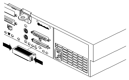
Remove the active SCSI terminator (metal cap) from the connector on the back of the server, or from the last external device connected to the unit.
If you are connecting the device to the Challenge S server, remove the terminator from the SCSI connector on the rear of the server by squeezing the clips on both sides of the terminator and pulling it off, as shown in Figure 6-5.
Save the terminator. You need to reconnect it to the system if you remove and do not replace the external device.
If you are daisy-chaining the external device to another external device, remove the terminator from the connector on the last device in the chain.
Choose the appropriate SCSI cable to connect the external SCSI device.
If you are attaching the device directly to the server, use a cable that has a 50-pin, high-density connector for the server and the appropriate connector on the other end.
To daisy-chain a device to another device, use the cable that has the correct connectors at each end.
-
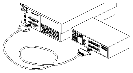
To connect the device to the server, connect the flat, smaller end of the cable to the port above the SCSI icon on the back of the server, as shown in Figure 6-6.
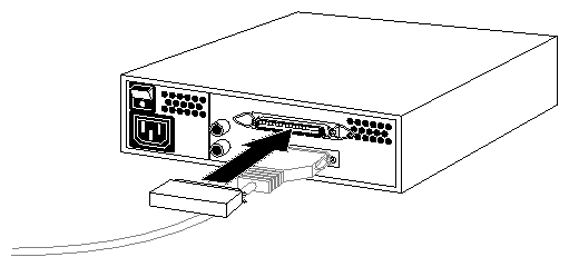
Connect the other end of the SCSI cable to one of the SCSI connectors on the back of the device and secure the clips (if applicable) on each side of the connector.
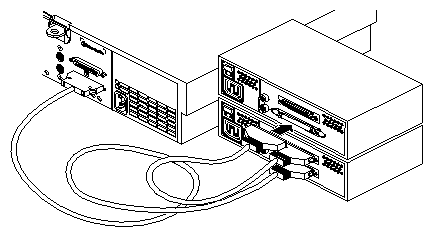
To daisy-chain the device to another external SCSI device, connect one end of the cable to the open connector on the first device, as shown in Figure 6-7. Connect the other end to one of the connectors on the device you are adding. Keep in mind the total cable length limit of two meters for controller 0. Use the shortest possible cable.
Connect the active terminator that you received with the external SCSI device to the open SCSI connector on the back of the last device on the daisy-chain, as shown in Figure 6-8.
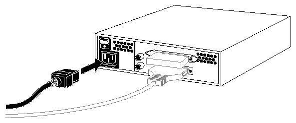
Connect one end of the power cable that came with the external device to the power connector on the back of the device, as shown in Figure 6-9. If you are finished connecting external devices, go on to the section “Testing the External SCSI Device”.
Plug the other end of the power cable into a grounded three-pronged (or other approved) electrical outlet.
Remember to power on the external devices first and then your system to make sure that the devices are recognized.
The IOPLUS is a GIO option board that provides two differential SCSI channels and an Ethernet 10 BASE-T port in the Challenge S server. You can identify this board by checking the connectors on the back of the server. The IOPLUS provides two narrow horizontal 68-pin SCSI connectors and one 10-BASE T Ethernet connector on the back (see Figure 2-4).
The SCSI connectors on the IOPLUS are used to attach external differential SCSI devices (such as disk and tape drives) to your server. Differential peripheral systems available from Silicon Graphics include
Each differential SCSI connector on the IOPLUS can communicate with up to 15 devices. Note that the cables connecting these devices must not exceed a total of 81 feet (25 meters).
| Caution: Do not connect single-ended SCSI devices to the IOPLUS. They will not function and will cause SCSI bus errors. |
Follow these steps to check that the system recognizes the new device.
Turn on the external SCSI device first. If there is more than one external device, you may turn them on in any order, as long you turn them on before the server. The power switch is usually on the back of the device.
Press and release the power button on the front of the system to power on the system.
At the System Maintenance menu, enter 5 to start the command monitor.
At the command monitor prompt (>>), enter the hinv command to list the devices recognized by the system:
hinv
If the device is not listed in the output from hinv, turn off the system and all the external SCSI devices, then repeat steps 1 through 4. If the devices are still not listed, there could be a problem with the cable, the device, or the system. See Chapter 8, “Troubleshooting” for tips on diagnosing the problem.
If the devices you installed are recognized (shown in the hinv listing), enter auto to boot the system.
The system should automatically detect and recognize any new SCSI devices.
If you installed an additional hard disk(s), you can now boot the system and configure the drive(s) for use with IRIX. The configuration process varies depending upon how many disks you have and how you want to use them. The basic process can include
formatting disks with the fx command, if they are not already formatted (drives purchased from Silicon Graphics are pre-formatted)
partitioning the disk, if you want multiple partitions, also using fx
creating device nodes to access the disk using the MAKEDEV command (depending upon how the disk is partitioned)
create filesystems on the disk, create mount points for those filesystems, and configure the system to automatically check and mount the filesystems (if desired) using the Add_disk command
In addition, you may want to grow an existing filesystem onto a new disk, increase swap space, create logical volumes, or stripe disks for increased system performance. For complete information on performing all of these tasks, see the fx(1m), makedev(1), and Add_disk(1) reference pages and the IRIX Advanced Site and System Administration Guide (for IRIX 5.3 systems) and IRIX Admin: Disks and Filesystems (for IRIX 6.2 systems).
You should configure additional drives in single-user mode. To enter single-user mode, follow these steps:
At the System Maintenance menu, enter 5 to start the command monitor.
At the command monitor prompt, enter this command:
single
The system boots up to single-user mode. You are automatically logged in as root, and are the only user on the system. All other serial ports are disabled, as are networking and other daemons. You can proceed with configuring the new disk(s).
When you have finished configuring the new disk(s), press <Ctrl-D> to bring the system up in multiuser mode.
This section tells you how to install serial devices. Serial devices include:
To install a serial device, follow these steps:
Unpack the serial device and cables.
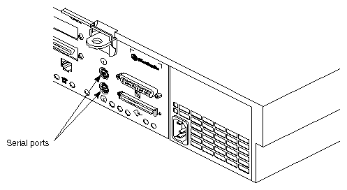
Locate the serial ports on the back of the Challenge S server, as shown in Figure 6-10.
The serial ports are labeled 1 and 2 and are MINIDIN 8 connectors. Port 1 is the console port. (Pinouts are described in Appendix A, “Cable Pinout Assignments.”)
Connect the serial cable. The Challenge S server ships with a serial cable that has a MINIDIN 8 connector at one end and a DB-25 connector at the other (Silicon Graphics part number 018-8114-001) that is appropriate for use with terminals or other data terminal equipment (DTE).
If you are connecting a console terminal, attach it to serial connector 1 only. If you are connecting another device, you can attach it to serial connector 2.
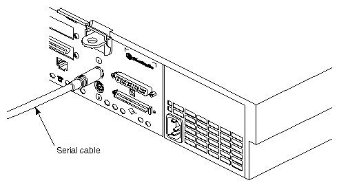
Connect one end of the serial cable into the connector on the back of the serial device. See the instructions that came with the serial device for detailed instructions on how to connect the cable to the device.
Connect the other end of the cable to the serial connector on the back of the Challenge S server, as shown in Figure 6-11.
Plug in the serial device's power cable.
For information on using other serial cables, turn to Appendix B, “Serial Cables.” For more information on serial ports, see the serial(7) reference page.
You can connect an optional ASCII terminal to your server by using the serial cable shipped with your Challenge S server. It has an 8-pin MINIDIN connector on one end and a 25-pin serial connector on the other (Silicon Graphics part number 018-8114-001). See “Printer/Character (ASCII) Terminal Serial Cable” in Appendix B for a description of this cable.
Be sure to read the documentation that comes with the terminal. Always connect your system console terminal to serial port 1. You can connect an additional terminal to port 2. Set the terminal with the following operational characteristics:
9600 baud
8 bits
1 stop bit
no parity
Use the following steps to properly connect a terminal:
Attach the keyboard (if applicable) and power connectors to the terminal.
Caution: Before plugging the terminal into either a 110-VAC or 220-VAC outlet, be sure that the electrical rating on the UL-CSA label is in either the 100–120 VAC or 200–240 VAC range, whichever applies. Connect the end of the serial cable that has the 25-pin connector to the back of the terminal. (Some terminals have more than connector on the back; if this is the case, choose the connector marked Modem or COMM. Consult your terminal's documentation if you are not sure which connector to use.)
Attach the end of the serial cable that has the MINIDIN 8 connector to either port 1 (if the terminal will be the system console) or port 2.
Power on the terminal.
Restart the system or continue with other peripheral connections as needed.
In some cases your console terminal may need special recognition from the system software. You can check or set up the system software to work under specific parameters by using the following:
Log in to the system as root.
Edit the file /etc/gettydefs to choose the proper baud rate, prompt, and line conditioning.
vi /etc/gettydefs
Modify the file /etc/inittab, if necessary, to enable getty on port tty_1. Enter
vi /etc/inittab
The line is listed under “on-board ports” and should appear similar to the following:
t1:23:respawn:/etc/getty ttyd1 co_9600 # alt console
After modifying the /etc/inittab file, inform init of any changes by entering
telinit q
Look in /etc/ttytype for the listed console port information. You should see lines similar to this:
?iris-tp console
iris-tp tport
?vt100 ttyd1
?vt100 ttym1
?vt100 ttyf1
?vt100 ttyd2
?vt100 ttym2
?vt100 ttyf2
?vt100 ttyd3
?vt100 ttym3
?vt100 ttyf3
...
The default terminal type for all terminals is vt100 and the system prompts you to confirm this. To keep the system from asking you what type of terminal you are using when you log in, remove the question marks from all lines in the file that correspond to the serial port (either 1 or 2). For example, to prevent the system from prompting for a terminal type on port 1, you would change these lines in /etc/ttytype:
...
vt100 ttyd1
vt100 ttym1
vt100 ttyf1
...
You can also change the terminal type that designated for the particular serial port by changing “vt100” to another shorthand terminal name. See Appendix D, “Supported Terminals” for a list of some terminals and shorthand names.
Add the following line to your ~/.login file. This sets the terminal type, syntax, erase, and kill parameters automatically when you log in:
eval `tset -s -Q'
Check terminal connection and function using the following commands:
cat /etc/group > /dev/ttyd1
ps -def | grep getty
A modem can be connected to your system by connecting a serial modem cable to the 8-pin connector labeled as serial port 2. The serial cable must be appropriate for data communications equipment (DCE): the data transmit and data receive pins are opposite those in a DTE cable. Also, the cable must provide full flow control. See “Modem Cable” in Appendix B for a description of this type of cable.
See the /etc/uucp/fix-hayes or /etc/uucp/fix-telebit files for information on specific modems supported, (see step 5).
The following general procedures are used when connecting a modem:
Make sure that the power switch on the modem is turned off.
Attach the serial cable to the modem.
Attach the connector on the other end of the cable to the second serial connector on the server's I/O panel (see Figure 6-10).
Attach the modem power cord and turn on the modem.
Install the UUCP subsystem (either eoe2.sw.uucp for IRIX 5.3 or eoe.sw.uucp for IRIX 6.2), if it is not already installed.

Note: The UUCP subsystem is shipped with the IRIX operating system, but is not installed by default. Confirm that the UUCP subsystem installed by using the versions(1M) command. If it is not installed, see the Software Installation Administrator's Guide (for IRIX 5.3 systems) or IRIX Admin: Software Installation and Licensing (for IRIX 6.2 systems) for instructions. Read the documentation that comes with your modem to determine model-specific connection and configuration procedures.
For additional information about configuring modems, see IRIX Advanced Site and Server Administration Guide (for IRIX 5.3 systems) and IRIX Admin: Peripheral Devices (for IRIX 6.2 systems). You may need to modify entries in the files /etc/inittab and /etc/uucp/Devices.
Additional useful information on modem operation and configuration is available on the cu(1) reference page.
See the following section for additional helpful serial port information.
To show the standard settings on a particular serial port, become superuser and enter
stty < /dev/ttydx |
Where x is the number of the tty port on which you want information.
To show the various settings on a particular serial port, enter
stty -a < /dev/ttydx |
To change the baud rate (the example is 2400) on a particular serial port, enter
stty 2400 < dev/ttydx |
For additional useful information on serial ports and configuration, see the reference (man) pages for the following:
cu
inittab
gettydefs
ttytype
terminfo
stty
termio
The following files are commonly used to properly configure serial port operation for the Challenge S server:
/etc/inittab
/etc/gettydefs
/etc/ttytype
/usr/lib/terminfo
/etc/uucp/Devices
/etc/uucp/Systems