This chapter provides an overview of the Challenge S chassis and the components that make up the system. In particular, it describes
differences between available models; see “Overview”
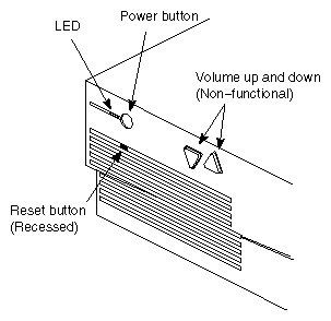
locations and functions of buttons; see “Front-Panel Controls”
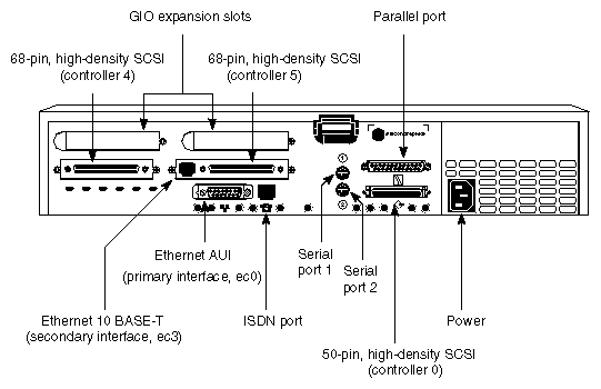
locations and functions of back-panel connectors; see “Locations and Functions of Back-Panel Connectors”
the power supply, including input and output voltages, amps, and watts; see “Power Supply”
internal drive options; see “Internal Drive Options”
system boards; see “System Boards”
system buses, memory, and I/O channels; see “System Buses and I/O Channels”
system specifications, including dimensions, weight, heat dissipation, and environmental considerations; see “System Physical Specifications”
The Challenge S server is currently available with four CPU types:
133 MHz MIPS® R4600PC
200 MHz MIPS R4400™SC
150 MHz MIPS R5000™PC
180 MHz MIPS R5000SC
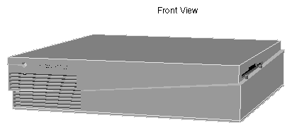
These models are visually identical and have the same connectors on the back of the chassis. Figure 2-1 and Figure 2-2 show the Challenge S server.
Table 2-1 briefly describes each of these systems.
Table 2-1. Overview of Challenge S models
CPU | Cache | Available I/O Channels |
|---|---|---|
16 KB each instruction and data caches | Three SCSI controllers (0, 4, & 5). Controller 0 is 16-bit, single-ended, 10 megatransfers per second (MTS)[a], shared between internal and external devices, 7 devices maximum (but limited to 2 meters cable length for all external devices). Controllers 4 and 5 are 16-bit, differential, 20 MTS, external only, 15 devices per controller maximum. Graphics Input/Output (GIO) bus with 1 or 2 additional GIO board capacity (depending upon the specific board). Single parallel port (bi-directional). Two serial ports, switchable between RS-232 and RS-422. ISDN basic-rate, RJ-45 connector. Ethernet AUI and Ethernet 10 BASE-T.
| |
MIPS R4400SC | 16 KB each instruction and data caches 1 MB secondary cache | (Same as above)
|
MIPS R5000PC | 32 KB each instruction and data caches | (Same as above)
|
MIPS R5000SC | 32 KB each instruction and data caches 512 KB secondary cache | (Same as above)
|
[a] Megatransfers are the number of million operations per bus cycle and are based on a bus's burst data rate. | ||
| Note: SCSI controllers on Challenge S are numbered 0, 4, and 5. Controllers 2 and 3 are reserved. |
There are four controls on the front panel of the Challenge S server.
The volume controls do not function on the Challenge S server because there is no audio subsystem on the system board.
Figure 2-3 shows the front-panel controls
Figure 2-4 shows the connectors on the backplane
Be aware that the secondary Ethernet interface, ec3, is not available until the system is booted. Only the primary Ethernet interface, ec0, is available when the system is in system maintenance mode.
Pinouts for all of the connectors are provided in Appendix A, “Cable Pinout Assignments.”
Table 2-2 shows how the various connectors correspond to IRIX (operating system) special device files.
Table 2-2. Correspondence of Connectors to IRIX Special Device Files
Connector | Device File |
|---|---|
/dev/tty[d,f,m]1 | |
Serial port 2 | /dev/tty[d,f,m]2 |
/dev/plp (standard parallel interface) /dev/plpbi (bi-directional interface) | |
/dev/dsk/dks0* (disks, CD-ROM) /dev/[r]mt/tps0* (generic SCSI tape) | |
/dev/dsk/dks4* (disks, CD-ROM) /dev/[r]mt/tps4* (generic SCSI tape) | |
68-pin, high-density SCSI, controller 5
| /dev/dsk/dks5* (disks, CD-ROM) /dev/[r]mt/tps5* (generic SCSI tape) |
For more information about serial devices, see serial(7). For information about the parallel port, see plp(7). For more information about SCSI devices and device names, see dks(7M) (for disks) and tps(7M) (for tape drives).
| Note: You cannot install your boot (system) disk on SCSI controllers 4 and 5. You can attach a boot (system) disk only to controller 0. |
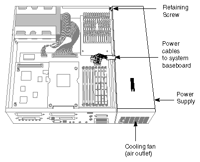
Features of the Challenge S power supply are as follows:
Figure 2-5 shows the Challenge S power supply.
The Challenge S chassis is designed to hold the system disk and one additional drive, either a floptical or an optional disk drive. These drives are driven by SCSI controller 0, which is also available on the external, 50-pin connector. (See Figure 2-4.) Controller 0 supports up to seven SCSI devices: up to two internally, and the remainder externally (provided the external cable length does not exceed 2 meters). Also, controller 0 is the only controller to which you can attach your system (boot) disk.
| Note: Because of cable-length restrictions, you may be limited to three external devices on SCSI controller 0. For example, if you use a one-meter cable to attach the first device, and half-meter cables for each additional device, this totals two meters of cable–the maximum cable length. |
The floptical must be installed in the top bracket. The system disk and option disks can be installed in either the top or bottom brackets.
| Warning: Always install the drive mounting brackets in the Challenge S chassis, even if the brackets are empty. The brackets are part of the chassis structural support. |
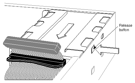
Internal drives are secured in removable mounting brackets with screws. The mounting brackets latch to the chassis by means of a catch, and can be installed and removed without additional tools.
Figure 2-6 shows the drive release button on a floptical drive. The release button for the system disk is identical.
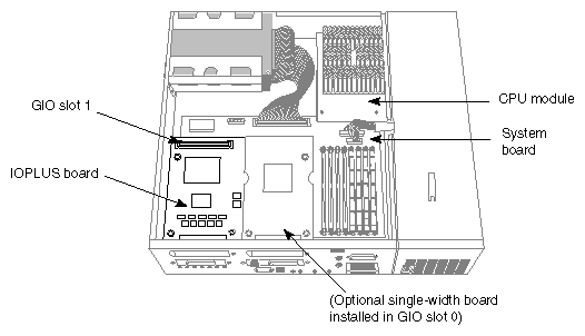
The three standard boards in the Challenge S server are:
Optional boards are installed on the GIO slot connectors of the IOPLUS board. Figure 2-7 shows the various standard boards, the GIO slot numbers, and an optional board.
| Note: Some systems may contain the GIO slot extender board. It occupies the same area as the IOPLUS (providing GIO slots 0 and 1), but does not contain SCSI controllers or Ethernet 10 BASE-T. |
The module consists of the CPU (an R4600, R4400, or R5000) with built-in floating-point unit (FPU) and primary cache, a 512 KB (R5000) or 1 MB (R4400) secondary cache, and an oscillator to set the processor speed. The CPU module is connected to the memory subsystem by a 64-bit (plus parity) multiplexed address and data CPU Bus.
The CPU module is replaceable separate from the system board. See Table 2-1 for a complete description of the CPU features.
This system board contains:
eight sockets for 36-bit wide (72-pin) SIMMs
the system PROM
GIO buses
a Fast SCSI-2 interface (10 megatransfers per second, 8 bits wide) as controller 0, supporting single-ended SCSI devices; you must attach the system disk to this controller
an ISDN interface
The section “System Buses and I/O Channels,” describes the architecture of the system.
The IOPLUS board provides
two Fast/Wide SCSI-2 controllers (20 megatransfers per second) as controllers 4 and 5, supporting up to fifteen differential SCSI devices per controller; you cannot attach the system disk to these controllers
connections (GIO slots 0 and 1) for either two single-width GIO option boards, or a single full-width GIO option board
The IOPLUS connects to the two GIO slots on the system board, and mounts on standoffs.
The next sections describe the various features of the Challenge S architecture.
The Challenge S server contains several custom ASICs to aid communication between the system and the buses:
The MC1 ASIC performs functions such as the GIO64 bus arbiter, which provides an interface between the CPU and the GIO64 bus. It is also the memory controller, allowing direct memory access (DMA) by devices other than the CPU. Note that DMA is supported only on GIO slot 0. See Figure 2-7.
DMUX1 ASICs are data path chips, controlled by the MC1 chip, that isolate the CPU bus from the GIO64 bus. They also perform the memory interleaving functions.
The HPC3 ASIC provides an interface to peripheral I/O and other devices on the P-Bus, connecting them to the GIO64 bus.
The IOC1 ASIC provides interrupt control, two general-purpose serial ports, and a parallel port.
The R4000® family of CPUs uses superpipelining to achieve fast internal speeds. In normal pipelining, the CPU breaks each instruction into separate one-cycle steps (usually fetch, read, execute, memory, and write back), then executes instructions at one-cycle intervals. Pipelining allows instructions to overlap, providing close to one instruction per cycle instead of one instruction every five cycles.
At the fast R4400 and R4600 CPU clock rates, some instruction steps such as cache reads and writes can't execute in a single pipelined cycle. Superpipelining executes each of these critically slow steps in a single cycle to provide higher throughput. To do so, it first breaks instruction steps into substeps. The substeps are then pipelined in a process separate from standard pipelining, which executes the full step in a single cycle. R4000 superpipelining is optimized so that it requires little control logic and instruction structure, unlike SuperScalar implementations.
The R4000 family of CPUs supports both the MIPS I and MIPS III instruction sets. Data pathways in MIPS III are 64 bits wide, enabling the system to load and store full floating point double words in a single machine cycle. The MIPS III instruction set also contains synchronization and advanced cache control primitives.
The R5000 CPU implements the MIPS IV instruction set. This instruction set provides four floating point multiply-add/subtract instructions which allow two separate floating point computations to be performed with one instruction. The R5000 processor also boosts its floating-point performance by reducing the repeat rate of many instructions from 2 cycles to 1. This allows those instructions critical to 3-D applications to be issued on every cycle, as opposed to every other cycle.
Separate integer and floating point arithmetic logic units (ALU's) allow a floating point ALU instruction to be issued simultaneously with any other instruction type. Whenever a floating point ALU instruction is fetched with any non-floating point ALU instruction, both instructions can be issued in the same cycle. Integer instructions do not have to wait for long-latency floating point operations to finish before being fetched, and vice versa. Load/store operations may also be issued simultaneously with floating point ALU instructions to reduce load latencies and bandwidth.
Like the R4400, the R5000 contains large, 32 KB instruction and data caches. Each cache is 2-way set associative, which helps to increase the hit rate over a direct-mapped implementation, and has a 32-byte fixed line size. Cache lines may be classified as write-through or write-back on a per-page basis.
The CPU subsystem is connected to the memory subsystem by a 64-bit wide (plus parity) data and address CPU bus. This bus consists of the R4600, R4400, and R5000 bus and control signals from the memory subsystem. Both can transfer data at a peak rate of 400 MB per second to and from the memory subsystem.
The memory subsystem contains memory control, data bus routing, and 8 SIMM sockets for main memory. A 64-bit (plus parity) multiplex address and data GIO64 bus connects the memory subsystem to I/O and the GIO expansion subsystems.
The memory subsystem uses two types of custom chips, the MC1 ASIC and the DMUX1 ASIC, to give the CPU access to main memory and the GIO64 bus and to isolate the CPU bus from the GIO64 bus.
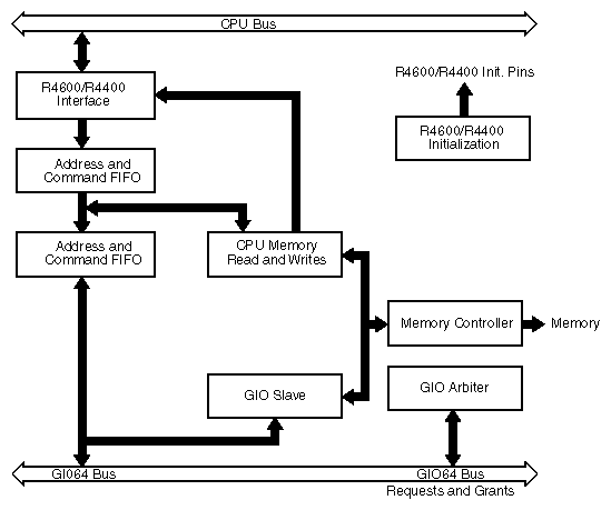
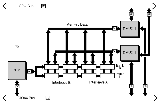
The MC1 ASIC, the memory controller (shown in Figure 2-8), is a custom Silicon Graphics chip connected to the CPU module by the CPU bus. It's also connected to the GIO64 bus (the I/O bus), and has address and control lines connected to main memory. It performs a number of functions:
It controls the flow of data between main memory and the CPU.
It serves as a DMA (direct memory access) controller for all memory requests from the graphics system or any other devices on the GIO64 bus (installed GIO slot 0 only; see Table 2-3).
It acts as a system arbiter for the GIO64 bus.
It provides single-word accesses for the CPU to GIO64 bus devices.
It passes on interrupts from the IOC1 ASIC to the CPU.
It initializes the CPU on power-on, executes CPU requests, refreshes memory, and checks data parity in memory.
The DMUX1 ASICs are a two-chip slice of a data crossbar between the CPU, main memory, and the GIO64 bus. The two DMUX1 chips are, together, a data path with control signals generated by the MC1. They isolate the CPU bus from the memory system and the GIO64 bus. They also contain synchronization FIFOs to perform flow control between the various subsystems and they interleave main memory to increase peak memory bandwidth.
Main memory is controlled by the MC1 and DMUX1 ASICs. Memory consists of 72-pin, 36-bit wide DRAM SIMMs (which must have 80 ns RAS access time and fast page-mode capability). Challenge S supports the following SIMM types:
4 MB
8 MB
16 MB
32 MB
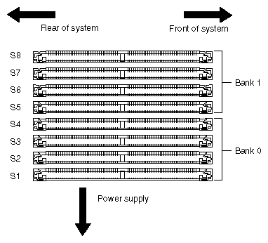
SIMMS are arranged in slots and banks, as shown in Figure 2-9.
DMUX1 chips interleave the SIMMs to create a 72-bit wide, two-way interleaved memory system. See Figure 2-10.
Main memory can be configured for between 16 MB and 256 MB. The system board has 8 SIMM sockets, arranged in two banks of four. Each bank must use SIMMs of the same size, but SIMM sizes can differ between banks.
The GIO64 bus, the main system bus, provides a 64-bit wide (plus parity) data path and is designed for very high speed data transfer. It connects the Challenge S main systems: the CPU, memory, I/O, and GIO expansion slots. The GIO64 is a synchronous, multiplexed address/data burst mode bus that runs at 33 MHz and is clocked independently of the CPU. The GIO64 bus can transfer data between main memory and any device on the bus at up to 267 MB per second.
| Note: The GIO interface is a published specification available to developers. |
The HPC3 ASIC (high performance peripheral controller) is the heart of the I/O subsystem. It is a custom Silicon Graphics chip that collects data from relatively slow peripherals, buffers it in FIFOs, then transfers it into main memory using high speed DMA transfers over the GIO64 bus. It also transfers data from main memory to peripheral devices in the same manner.
The HPC3 has direct interfaces to the GIO64 bus, to a SCSI-2 port, to an Ethernet port, and to the 16-bit P-Bus (peripheral bus). The SCSI-2 and Ethernet ports are connected directly for increased bandwidth. The P-Bus is a 20-bit address, 16-bit data bus used by the HPC3 for additional peripheral support. It connects the boot PROM, a real-time clock, the ISDN interface, and the IOC1 ASIC. The IOC1 integrates an interrupt handler, two general purpose serial ports, and a parallel port. There is a 384-byte memory buffer that is shared by all of the P-Bus devices to buffer DMA transfers to and from memory.
The IOPLUS I/O expansion subsystem includes its own HPC3 ASIC connected directly to the GIO64 bus. This additional HPCS supports the additional Ethernet controller and the two Fast and Wide SCSI-2 controllers provided by the optional subsystem.
The standard Ethernet interface consists of an AUI Ethernet port supported by a controller that is connected directly to the HPC3 ASIC. The HPC3 supplies the logic required to retransmit packets when collisions occur and to manage the interface's 64-byte FIFO buffer. When the HPC3 receives a packet, it writes the packet into memory, then interrupts the CPU. When transmitting, it interrupts the CPU each time a packet is successfully sent or when 16 transmission attempts have all failed.
The IOPLUS I/O expansion subsystem provides an additional Ethernet 10 BASE-T port. Both Ethernet interfaces can be used at the same time. However, the 10 BASE-T port is not active until after the system is booted.
The standard 10 MB per second, Fast SCSI-2 interface consists of one controller (controller 0) shared between internal and external devices. The controller supports two internal SCSI devices, and up to five external SCSI devices (provided the external cable length does not exceed two meters), through a high-density, single-ended SCSI port on the rear of the system unit.
| Note: Because of cable-length restrictions, you may be limited to three external devices on SCSI controller 0. For example, if you use a one-meter cable to attach the first device, and half-meter cables for each additional device, this totals two meters of cable–the maximum cable length. |
The Fast SCSI-2 controller is supported by a SCSI controller connected directly to the HPC3 ASIC. The HPC3 uses a FIFO buffer to enable burst use of the GIO64 bus.
The IOPLUS I/O expansion subsystem provides two additional Fast, Wide, and differential SCSI-2 controllers (controllers 4 and 5) providing 20 MB of maximum bandwidth per controller (40 MB total). These controllers support a maximum of 18 meters of cable length. Be aware that these controllers are not active until the system has already started booting.
Silicon Graphics defines bus speeds for its SCSI controllers in megatransfers per second. Megatransfers are the number of million operations per bus cycle. An operation is either 8 or 16 bits in size. Megatransfers are based on a bus's burst data rate. Total data transfer rates depend on the bus bandwidth.
The parallel interface consists of a 400 KB per second, bi-directional Centronics® parallel port. The port is controlled by the IOC1 ASIC that connects to the P-Bus, and provides a FIFO buffer used to transfer data between main memory and the parallel port at up to 1.0 MB per second.
The serial interface consists of two serial ports, controlled by the IOC1 ASIC that connects to the P-Bus. The serial ports are software programmable for RS-422 (differential) and RS-232 standards, and support a transfer rate of up to 38.4 kilobits (Kb) per second. The RS-422 standard allows the use of common Macintosh® peripherals such as laser printers and scanners. Support for MIDI timing is also provided.
Challenge S supports a single ISDN basic rate interface integrated onto the system board. Access to the ISDN is provided at the “S” access point. The design provides a single hardware implementation that is certifiable throughout the world.
With IRIX 5.3, the subsystem isdn_eoe must be installed in order for the ISDN interface to operate. ISDN for the Challenge S server works with the following switch protocols in the United States:
DMS100
5ESS
National ISDN1
ISDN on the Challenge S server has been approved for the following switch protocols in the following countries:
1TR6 in Germany
Euro-ISDN in Germany, Sweden, and Finland
NTT in Japan
Countries other than those listed above may require testing and approval before ISDN can be used with the Challenge S server in that country. Contact your local service provider or Silicon Graphics for more information.
The ISDN Basic Rate Interface on the Challenge S server supports the Point-to-Point Protocol (PPP). PPP enables TCP/IP networking across ISDN B-channels, providing the full 64 kilobits (Kb) per second bandwidth of each B-channel. Both B channels can be combined using a round-robin packet-sending scheme to maximize throughput. This is sometimes called inverse multiplexing, and is similar to bonding.
The Application Software Interface (ASI) being developed by the National ISDN User's Forum is expected to become a standard in the USA. For information on programing with ASI, see the isdn_eoe Release Notes (available on-line using the relnotes command).
ISDN features include
a single “S” RJ45 access connector
hardware HDLC framing on both B-channels for data communications and networking applications
three DMA channels (one channel to transmit and one for each receive direction on each B-channel)
separate 64-byte transmit and receive FIFOs on each B-channel and on the D-channel
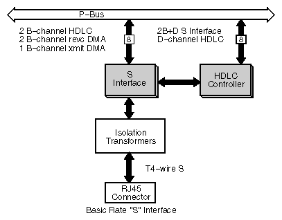
A block diagram of the Challenge S ISDN architecture is shown in Figure 2-11.
The interface is based on the S interface chip and the HDLC controller chip. The S interface chip provides the interface to the four-wire S interface, HDLC formatting on the D-channel, two FIFOs for the D-channel transmit and receive data, and host access to the D-channel data. The HDLC controller chip provides the DMA interface to the B-channels, HDLC formatting on the B-channels, and four FIFOs for the B-channel transmit and receive data. The isolation transformers provide the coupling and high voltage isolation between the S interface and the Challenge S system.
The S interface chip and the HDLC controller chip are both connected to the P-Bus in the Challenge S system. Both chips contain registers that may be accessed by the host CPU. The HDLC controller chip is connected to three DMA channels that are contained in the HPC3 ASIC.
The two GIO32-bis expansion slots, connected directly to the GIO64 bus, provide direct access to the system for Silicon Graphics and third party plug-in boards for such applications as high-speed networking, image compression, video deck control, and additional I/O.
GIO32-bis is a cross between GIO32 and GIO64. It can be considered a 32-bit version of the non-pipelined GIO64 or a GIO32 with pipelined control signals.
| Note: Only GIO slot 0 has DMA available for option boards. (See Figure 2-7.) If a GIO option board uses DMA, it must be installed in slot 0. The only exceptions to this rule are the Silicon Graphics GIO32 SCSI and Ethernet E++ boards. |
Table 2-3 lists the GIO slot dependencies.
Table 2-3. GIO Slot Dependencies
GIO Slot | DMA Available | Board Restrictions |
|---|---|---|
0 | Yes | GIO32 SCSI and Ethernet (E++) boards may not be installed (any boards that use the HPC1.5 ASIC). Any other option board that requires DMA must be installed in this slot. |
1 | No | GIO32 SCSI and Ethernet (E++) boards must be installed in this slot (any boards that use the HPC1.5 ASIC). Note: if the GIO32 SCSI or E++ boards are installed, no other boards requiring DMA may be installed in the system, even in slot 0. |
Table 2-4 lists the physical specifications of the system.
Table 2-4. System Physical Specifications
Specification | Value |
|---|---|
Dimensions | 3in. H x 16in. W x 14in. D (7.6 cm H x 40.6 cm W x 35.6 cm D) |
Net Weight | 16 lbs (7.2 kg) |
Environmental (Non-Operating) Temperature Humidity Altitude |
–40 to 149˚ F (–40 to +65˚ C) 5% to 95% non-condensing 40,000 MSL |
Environmental (Operating) Temperature Humidity Altitude Noise Vibration |
+55 to +95˚ F (+13 to +35˚ C) 10% to 80% non-condensing 10,000 MSL 36 dBA 0.02in., 5-19 Hz |
Heat dissipation | 1000 Btu/hr., maximum |
