This chapter describes how to operate your SGI Origin 300 system with NUMAlink module. Specifically, it explains how to perform the following procedures:
The system console enables you to perform the following activities:
Monitor your system by reading the status and error message information that the L1 and L2 controllers generate.
Enter L1 and L2 controller commands to monitor or change particular system functions. You can, for example, monitor the speed of fans for a particular module.
Power on or power off individual modules or all modules (except for the storage modules) in your system.
If you connect a console that contains SGIconsole software, you can perform the functions listed above and have boundary scan capabilities. Boundary scan capabilities enable an SGI system support engineer (SSE) to test the functionality of your system.
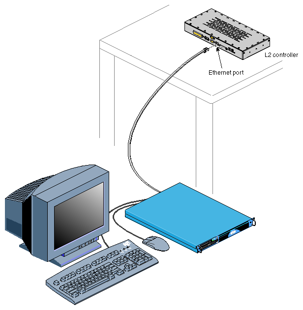
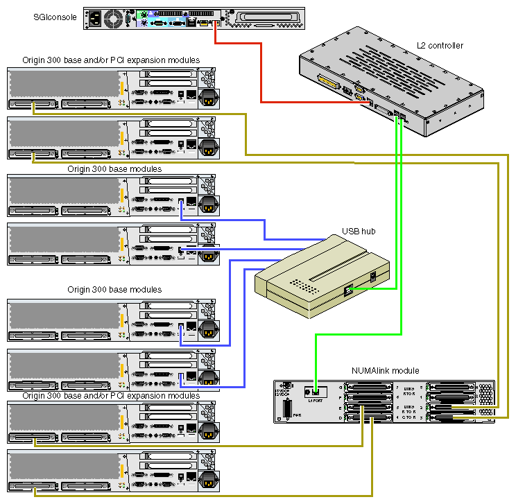
To attach a system console that runs the SGIconsole software to your system, connect the system console to the L2 controller Ethernet port connector as shown in Figure 3-1.
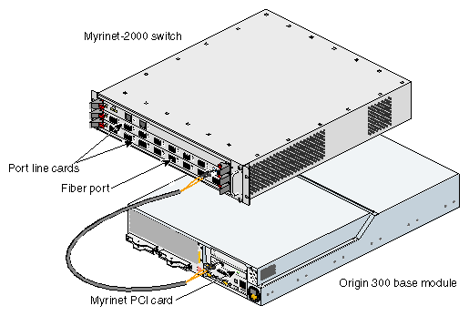
SGI ships your system with all Myrinet hardware installed in the rack: the Myrinet PCI cards are installed in the Origin 300 base modules (refer to Figure 3-2), and the Myrinet-2000 switch is installed in rack 001 or 002, depending on your configuration. The system does not ship with the fiber cables attached to the hardware.
To attach the fiber cables, connect one end of a fiber cable to a Myrinet PCI card in an Origin 300 base module. Connect the other end of the fiber cable to a fiber port of one of the port line cards in the Myrinet-2000 switch. It does not matter which fiber port you use.
In addition to attaching the fiber cables, ensure that the Myrinet-2000 switch is connected to a power distribution unit (PDU) or power strip.
For software setup, refer to the release notes (relnotes) that are provided with the Myrinet software. After you install the software, use the relnotes and grelnotes (graphics viewer for online release notes) to configure and validate the Myrinet-2000 switch.
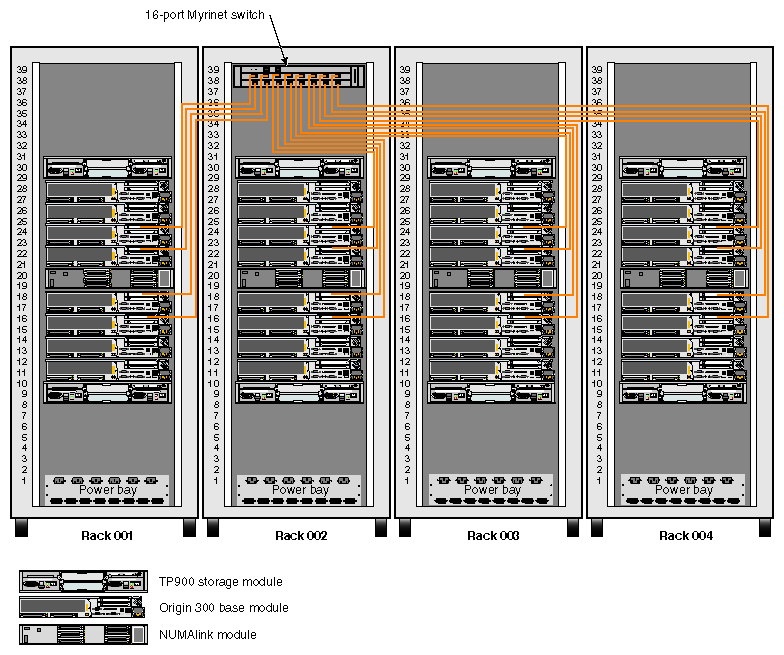
Figure 3-3 illustrates a 128-processor clustered system.
You can install or remove peripheral component interface (PCI) cards, disk drives, and memory that reside in the base modules in your system. This section explains how to perform the following procedures:
Installing or removing a PCI card
Installing or removing a disk drive
Installing or removing memory

Warning: For your safety and the protection of your system, contact your SGI system support engineer (SSE) to install or remove any other hardware components.
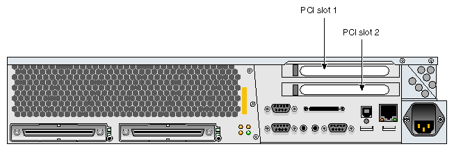
Each Origin 300 base module has two Universal PCI 2.2-compliant option card slots that are configured on one bus (refer to Figure 3-4). The PCI bus supports both 32- and 64-bit addressing modes at 33 or 66 MHz. Refer to the SGI Supportfolio Online home page for an updated list of supported PCI cards: http://support.sgi.com
| Note: The PCI slots of the Origin 300 base module can seat 3.3-V or Universal PCI cards. The Origin 300 base module does not support 5-V only PCI cards. |
This section explains how to perform the following procedures:
Installing a PCI card
Removing a PCI card
Tools/Parts Required:
PCI card
T10 ballpoint Torx driver P/N 7260650
T20 ballpoint Torx driver P/N 7260422

Caution: Electronic equipment can be irreparably damaged by electrostatic discharge (ESD). Always follow these preventive measures when you handle a system component:
- Remove a component from its antistatic bag only when you are ready to install it.
- If you handle a component before installation, do not place it on surfaces that produce ESD (carpeting, for example) or near devices that create static electricity.
- Attach a static wrist strap to a grounded connection on your system when you install or remove a component.
Follow these steps to install a PCI card:
Power off the system. For instructions on how to power off the system, refer to “Powering Off”.
Disconnect all of the cables at the rear of the base module.

Warning: Components may be hot. To avoid injury, allow the components to cool for approximately 5 minutes before you proceed with these instructions. Remove the two screws that secure the base module to the front rails of the rack.
Pull the base module from the rack until it is stopped by the safety latches.

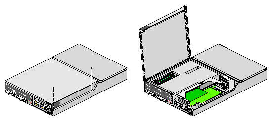
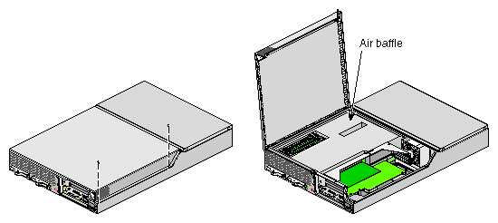
Note: If you are installing a full-height PCI card in the lower slot (PCI slot 2), you must remove the base module from the rack. For instructions on how to remove a base module from the rack, refer to “Removing a Base Module from a Rack”. To access the PCI card, remove the two screws shown in Figure 3-5 and lift and remove the hinged cover.
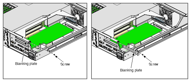
If a blanking plate covers the slot that is needed for the installation, remove the retaining screw as shown in Figure 3-6 and the blanking plate.
Insert the PCI card into the slot by pushing the card into the connector until it is properly seated.
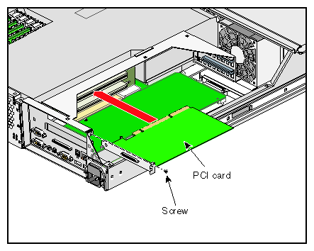
Install the retaining screw as shown in Figure 3-7.
Attach the hinged cover and secure it to the base module with two screws.

Note: If you removed the base module from the rack, refer to “Installing a Base Module in a Rack” for instructions on how to install the base module in the rack. Press the safety latches on both sides of the base module and slide the base module into the rack.
Install the two screws that secure the base module to the front rails of the rack.
Install all of the cables at the rear of the base module.
Power on the system. For instructions on how to power on the system, refer to “Powering On”.
To remove a PCI card, follow these steps:
Power off the system. For instructions on how to power off the system, refer to “Powering Off”.
Disconnect all of the cables at the rear of the base module.

Warning: Components may be hot. To avoid injury, allow the components to cool for approximately 5 minutes before you proceed with these instructions. Remove the two screws that secure the base module to the front rails of the rack.
Carefully pull the base module from the rack until it is stopped by the safety latches.

Note: If you are removing a full-height PCI card from the lower slot (PCI slot 2), you must remove the base module from the rack. For instructions on how to remove a base module from the rack, refer to “Removing a Base Module from a Rack”. To access the PCI card, remove the two screws shown in Figure 3-8 and lift and remove the hinged cover.
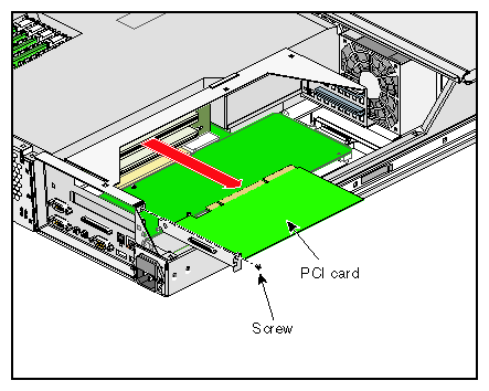
Release the retaining screw of the card as shown in Figure 3-9.
Gently pull the card straight out of the slot.
Install a new PCI card or a blanking plate as described in “Installing a PCI Card”.
Attach the hinged cover and secure it to the base module with two screws.

Note: If you removed the base module from the rack, refer to “Installing a Base Module in a Rack” for instructions on how to install the base module in the rack. Press the safety latches on both sides of the base module and slide the base module into the rack.
Install the two screws that secure the base module to the front rails of the rack.
Install all of the cables at the rear of the base module.
Power on the system. For instructions on how to power on the system, refer to “Powering On”.
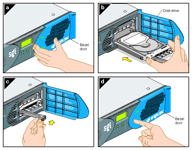
Each Origin 300 base module can contain one or two sled-mounted Ultra3 SCSI disk drives (refer to Figure 3-10).
Tools/Parts Required:
One or more of the following disk drives/blanks:
18-GB disk drive P/N 013-3485-00x
73-GB disk drive P/N 013-3486-00x
Disk drive blank P/N 9470464
To install a disk drive, follow these steps:
Open the bezel door as shown in Figure 3-11a.
Position the drive assembly so that it engages the bay guide rails and gently push the drive into the bay (refer to Figure 3-11b).
Swing the locking handle towards the chassis until the locking handle engages the latch (refer to Figure 3-11c).
Close the bezel door as shown in Figure 3-11d.
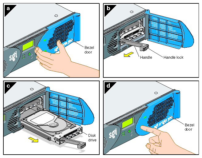
To remove a disk drive, follow these steps:
If you are replacing a data drive, ensure that the drive has spun down before removing it.
Open the bezel door as shown in Figure 3-12a.
Remove the drive by depressing its handle lock with your thumb and pulling the handle away from the chassis until the handle disengages the drive connector from the backplane connector (refer to Figure 3-12b).
Carefully slide the drive out of the bay (refer to Figure 3-12c) and place it on an ESD-safe surface. Do not use the handle to pull the drive out of the bay.
Close the bezel door as shown in Figure 3-12d.
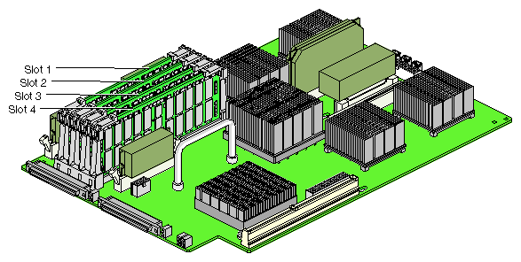
Memory is contained on cards that are referred to as DIMMs (dual-inline memory modules). Each Origin 300 base module can contain two or four DIMMs. If you are adding memory to your system, populate the DIMM slots in the following order (refer to Figure 3-13):
Slots 1 and 3
Slots 2 and 4
The DIMMs that reside in slots 1 and 3 or slots 2 and 4 must be the same memory size; however, the DIMMs in slots 1 and 3 may be a different memory size than the DIMMs in slots 2 and 4.
| Note: The DIMMs used in the SGI Origin 300 base module are not compatible with the DIMMs used in Origin 200, Origin 2000, Onyx2, or Octane systems. |
| Caution: Electronic equipment can be irreparably damaged by electrostatic discharge (ESD). Always follow these preventive measures when you handle a system component: - Remove a component from its antistatic bag only when you are ready to install it. - If you handle a component before installation, do not place it on surfaces that produce ESD (carpeting, for example) or near devices that create static electricity. - Attach a static wrist strap to a grounded connection on your system when you install or remove a component. |
Tools/Parts Required:
One or more of the following DIMMs:
DIMM 256-MB P/N 030-1018-00x
DIMM 512-MB P/N 030-1044-00x
DIMM 1-GB P/N 030-1060-00x
T20 ballpoint Torx driver P/N 7260422
To install a DIMM, follow these steps:
Power off the system. For instructions on how to power off the system, refer to “Powering Off”.
Disconnect all of the cables at the rear of the base module.

Warning: Components may be hot. To avoid injury, allow the components to cool for approximately 5 minutes before you proceed with these instructions. Remove the two screws that secure the base module to the front rails of the rack.
Pull the base module from the rack until it is stopped by the safety latches.
The access the DIMMs, remove the two screws shown in Figure 3-14 and lift and remove the hinged cover.
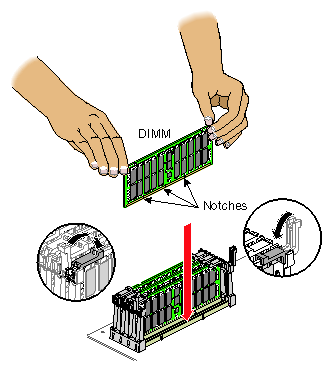
Install the DIMM, as follows (refer to Figure 3-15):

Note: You do not have to remove the air baffle to install a DIMM. Ensure that the ejector latches are open.
Holding the DIMM only by its edges, remove it from its antistatic package.
Align the three notches in the bottom edge of the DIMM with the keyed socket, as shown in Figure 3-15.
Insert the bottom edge of the DIMM into the socket, and then press down on the DIMM until it seats correctly. Use extreme care when installing a DIMM. Applying too much pressure can damage the socket.
Gently push the plastic ejector latches down to secure the DIMM, as shown in Figure 3-15. When the DIMM is fully seated in the connector, the ejector latches snap into place.
Attach the hinged cover and secure it to the base module with two screws.
Press the safety latches on both sides of the base module and slide the base module into the rack.
Install the two screws that secure the base module to the front rails of the rack.
Install all of the cables at the rear of the base module.
Power on the system. For instructions on how to power on the system, refer to “Powering On”.
To remove a DIMM, follow these steps:
Power off the system. For instructions on how to power off the system, refer to “Powering Off”.
Disconnect all of the cables at the rear of the base module.

Warning: Components may be hot. To avoid injury, allow the components to cool for approximately 5 minutes before you proceed with these instructions. Remove the two screws that secure the base module to the front rails of the rack.
Pull the base module from the rack until it is stopped by the safety latches.
The access the DIMMs, remove the two screws shown in Figure 3-16 and lift and remove the hinged cover.
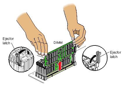
Remove the DIMM, as follows (refer to Figure 3-17):

Note: You do not have to remove the air baffle to remove a DIMM. Lift the two ejector latches simultaneously to disengage the DIMM from its connector.
Carefully grasp the DIMM and pull it up and out of the guide rails.

Note: Hold the DIMM only by its edges. Be careful not to touch its components or gold edge connectors. Place the DIMM on an ESD-safe surface.
Insert a new DIMM as described in “Installing a DIMM ”.
Attach the hinged cover and secure it to the base module with two screws.
Press the safety latches on both sides of the base module and slide the base module into the rack.
Install the two screws that secure the base module to the front rails of the rack.
Install all of the cables at the rear of the base module.
Power on the system. For instructions on how to power on the system, refer to “Powering On”.
To remove a base module from the rack, follow these steps:
Power off the system. For instructions on how to power off the system, refer to “Powering Off”.
Disconnect all of the cables at the rear of the base module.

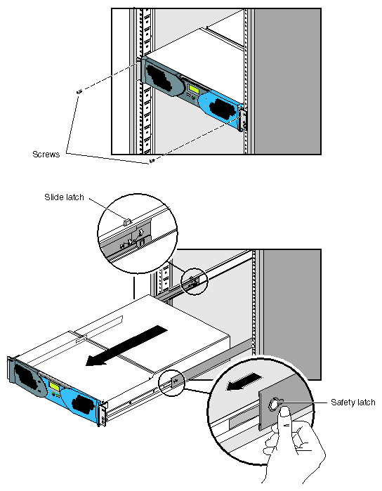
Warning: Components may be hot. To avoid injury, allow the components to cool for approximately 5 minutes before you proceed with these instructions. Remove the two screws that secure the base module to the front rails of the rack.
With a person on each side of the base module, pull the base module out of the rack until the safety latches stop the base module (refer to Figure 3-18).
Press the safety latches on both sides of the base module and pull the base module out of the slide rail (refer to Figure 3-18).
Place the base module on a flat, stable surface.
To push the slide rail back into the rack, press the slide latch to release the rail. There is one slide latch for each rail. On one rail, the slide latch is located on top of the rail (refer to Figure 3-18). On the other rail, the slide latch is located on the bottom of the rail.
To install a base module in the rack, follow these steps:
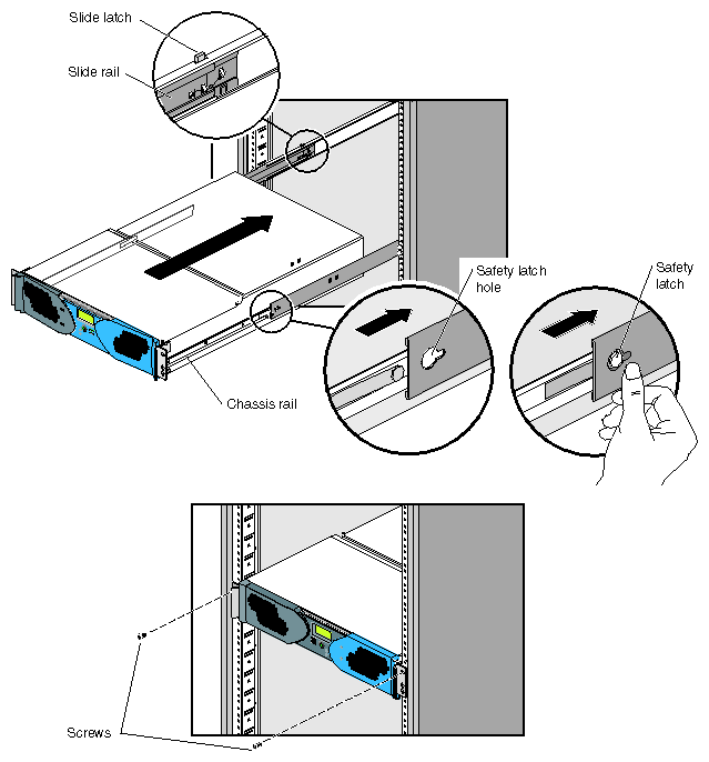
Fully extend both the left and right slide rails from the rack until they lock into place (refer to Figure 3-19).
Using two people, line up the chassis rails with the slide rails and slide the base module into the rack until the safety latches stop the base module (refer to Figure 3-19).
Press the safety latches on both sides of the base module and slide the base module into the rack (refer to Figure 3-19).
Install the two screws that secure the base module to the front rails of the rack.
Install all of the cables at the rear of the base module.
Power on the system. For instructions on how to power on the system, refer to “Powering On”.
The following sections describe how to power on and power off individual modules or your entire SGI Origin 300 system.
You can power on and power off individual modules and the entire system via the system console.
| Note: The following information applies to the Origin 300 base modules, the NUMAlink module, and PCI expansion modules. You must manually power on a TP900 storage module by placing the power switch(es) in the 1 position. Refer to Figure 3-20. |
This section describes how to perform the following procedures:
Preparing to power on
Powering on at the system console
Powering on with power buttons
| Warning: The rackmount system operates on 200-240 Vac. Use extreme caution when you work near this voltage. |
To prepare to power on the system, perform the following tasks:
Confirm that the power cables between the following components are secure:
Between the power distribution unit (PDU) and the external power receptacle.
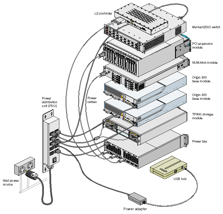
Between the PDU and the following components: Origin 300 base module(s), AC-powered NUMAlink module, USB hub, TP900 storage module(s), power bay, power strip, L2 controller power supply, and Myrinet-2000 switch.
Between the power bay and the following modules: DC-powered NUMAlink module, PCI expansion module(s), and L2 controller module (refer to Figure 3-21).

Note: When the system contains an AC-powered NUMAlink module, the L2 controller does not receive power from a power bay; instead, it receives power from a power supply. This power supply receives AC voltage from a PDU or power strip and converts the voltage to 48 Vdc, which is the input voltage that the L2 controller requires.
Figure 3-21 shows the PDU and power bay connections to the components within a system that contains a DC-powered NUMAlink module.
Confirm that the cables between the L2 controller and the following components are secure:
NUMAlink module (refer to Figure 3-22)
USB hub
Figure 3-22 shows how the system components connect to the L2 controller.
Ensure that the power switch on each DC-powered NUMAlink and PCI expansion module that you want to power on is set to the On (1) position. The power switch is located in the upper-left corner of the module (refer to Figure 3-23). This switch enables the L1 controllers of the NUMAlink module and PCI expansion modules to power on after you turn on the circuit breaker of the PDU.

Note: The Origin 300 base and AC-powered NUMAlink modules do not have a power switch; when the PDU circuit breaker is on, their L1 controllers are on.
Power on the system as follows:
If the monitors and other peripherals are equipped with voltage select switches, verify that they are set for the appropriate AC voltage and plug them in. Note that they are normally plugged into sources outside the rack system.
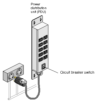
Turn on the circuit breaker switch of the PDU as shown in Figure 3-24.
Verify that all of the L1 controllers display “L1 running.” If any L1 controllers are not running, contact your SGI system support engineer (SSE).
At the system console, access the L2 controller by entering the following command:
$> /stand/sysco/bin/12term
From the L2 prompt, display the system configuration by entering the following command:
L2> cfg
This command lists the modules that the L2 controller detects in the system and their system controller addresses. If a module that you want to power on does not appear in the list, it will not power on. Ensure that the module's L1 controller is running and that it is cabled properly.
From the L2 prompt (L2>), power on an individual module by entering the following command. (If you want to power on the entire system, proceed to Step 7.)
L2> r <rack#> s <slot#> pwr u
For example, to power on an Origin 300 base module in rack 1, slot 18, enter the following command:
L2> r 1 s 18 pwr u
The slot number is the unit number of the module within the rack. For more information about unit numbers, refer to Chapter 1 of this document.
If you want to power on several selected modules of a rack at the same time, you must enter the rack number followed by the slot numbers of the modules that you want to power on. For example, to power on the modules in slots 18, 20, and 22, enter the following command:
L2> r 1 s 18,20,22 pwr u
If you want to power on the entire system, enter the following command:
L2> pwr u
(The default setting for the pwr u command is all racks and slots.)
When the L2 prompt appears, you will not see the output that is produced during the power-on procedure unless you redirect the keyboard input from the L2 controller to the normal console by typing control d.
L2> ctrl d
When the power-on procedure completes, the System Maintenance Menu appears on the system console. Select option 1 “Start System” to boot the IRIX operating system.
If your system does not have a system console, you can power on your system manually by using power buttons. Each module that has an L1 controller has a power button with an LED; this button is located on the front of the module (refer to Figure 3-25). The TP900 storage module power switch(es) are located at the rear of the module (refer again to Figure 3-20).
Power on the system as follows:
If the monitors and other peripherals are equipped with voltage select switches, verify that they are set for the appropriate AC voltage and plug them in. Note that they are normally plugged into power sources outside the rack system.
Turn on the circuit breaker switch of the PDU as shown in Figure 3-26.
Set the power switch(es) of the TP900 storage module(s) to the On position.
Verify that all of the L1 controllers display “L1 running.” If any L1 controllers are not running, contact your SGI system support engineer (SSE).
Press the power buttons that are located on the front of the modules that you want to power on. Always power on the PCI expansion modules first. Next, power on the NUMAlink module. Last, power on the Origin 300 base modules starting with the global master (the lowest base module in the rack).
The power-button LEDs illuminate when the modules are powered on.
This section explains how to power off individual modules or your entire system from the system console or via the power buttons. Power off the system only after the system software has been shut down in an orderly manner.
| Caution: If you power off the system before you halt the operating system, you can lose data. |
| Note: The following information applies only to Origin 300 base modules, the NUMAlink module, and PCI expansion modules. You must manually power off the TP900 storage module by placing the power switch(es) in the 0 position. Refer to Figure 3-27. |
To power off your system using the system console, follow these steps:
Shut down the IRIX operating system by entering the following command:
# init 0
To access the L2 prompt, direct the keyboard input to the L2 controller by entering control t.
$> ctrl t
From the L2 prompt (L2>), power off an individual module by entering the following command. (If you want to power off the entire system, proceed to Step 4.)
L2> r <rack#> s <slot#> pwr d
For example, to power off an Origin 300 base module in rack 1, slot 18, enter the following command:
L2> r 1 s 18 pwr d
The slot number is the unit number of the module within the rack. For more information about unit numbers, refer to Chapter 1 of this document.
If you want to power off several selected modules from the rack at the same time, enter the rack number followed by the slot numbers of the modules that you want to power off. For example, to power off the modules in slots 18, 20, and 22, enter the following command:
L2> r 1 s 18,20,22 pwr d
If you want to power off all of the modules within the rack, enter the following command:
L2> pwr d
(The default setting for the pwr d command is all racks and slots.)
“Powered Down” appears on the L1 display when the module is powered off. The L1 controller is still powered on.
To power down an L1 controller of a DC-powered NUMAlink or PCI expansion module, set the power switch to the Off position. The power switch of the NUMAlink or PCI expansion module is located in the upper-left corner of the rear of the module.

Note: The Origin 300 base and AC-powered NUMAlink modules do not have a power switch. To power down their L1 controllers, unplug the modules from the PDU.
To power off your system manually, follow these steps:
Shut down the IRIX operating system by entering the following command:
# init 0
Press the power buttons that are located on the front of the modules that you want to power off. You may power off the modules in any order.
To power off an L1 controller of a DC-powered NUMAlink or PCI expansion module, set the power switch to the Off position. The power switch of the NUMAlink or PCI expansion module is located in the upper-left corner at the rear of the module.

Note: The Origin 300 base and AC-powered NUMAlink modules do not have a power switch. To power off their L1 controllers, unplug the modules from the PDU.
You can monitor your SGI Origin 300 system from the following sources:
You can view individual module (base, NUMAlink, and PCI expansion) status and error messages via the module's L1 controller display. For example, you can determine whether the fans of a particular module are operating properly.
The system console enables you to view the status and error messages that are generated by both the L1 and L2 controllers. Refer to Appendix C, “System Controller Commands” for L1 and L2 commands.
You can monitor the status of the TP900 storage modules by viewing the LEDs on the front and the rear of the storage modules.
You can use the Embedded Support Partner (ESP) system, which is discussed in the next section.
Embedded Support Partner (ESP) automatically detects system conditions that indicate potential future problems and then notifies the appropriate personnel. This enables you and SGI system support engineers (SSEs) to proactively support systems and resolve issues before they develop into actual failures.
ESP enables users to monitor one or more systems at a site from a local or remote connection. ESP can perform the following functions:
Monitor the system configuration, events, performance, and availability.
Notify SSEs when specific events occur.
Generate reports.
ESP also supports:
Remote support and on-site troubleshooting.
System group management, which enables you to manage an entire group of systems from a single system.
For more information about ESP, refer to Chapter 5, “Troubleshooting.” For information about configuring ESP, refer to the Embedded Support Partner User Guide.
