This chapter describes the steps you must perform to unload and move the equipment, and to install your tall-rack or short-rack system. Specifically, it describes the following:
-

Note: Read this entire chapter before you install your system.
Before you install an SGI Origin 300 system with NUMAlink module, you should familiarize yourself with the following items, which are discussed in the subsections that follow.
Hazard statements
ESD precautions
Safety precautions
Preinstallation activities
During the installation of the computer system, be alert for hazard advisory statements. The following list describes the hazard statement signal words:
Danger indicates an imminently hazardous situation that, if not avoided, will result in death or serious injury.
Warning indicates a potentially hazardous situation that, if not avoided, could result in death or serious injury.
Caution indicates a potentially hazardous situation that, if not avoided, can result in minor or moderate injury. This signal word is also used to alert personnel against unsafe practices that can result in equipment damage and/or data corruption.
Observe electrostatic discharge (ESD) precautions during the entire installation process to eliminate possible ESD damage to the equipment. Wear an SGI-approved wrist strap when you handle an ESD-sensitive device. Connect the wrist strap cord directly to earth ground.
| Caution: Observe all ESD precautions. Failure to do so can result in damage to the equipment. |
Observe the following safety measures when you install the system.
Use caution when you remove the system from the shipping crate. Failure to handle the system carefully can result in personal injury or property damage.
Ensure that the shipping crate is positioned close to its destination before you unpack the crate.
Do not move the system while it is connected to power.

Caution: Keep fingers and conductive tools away from high-voltage areas. Failure to follow these precautions will result in serious injury or death. The high-voltage areas of the system are indicated with high-voltage warning labels. Ensure that a qualified electrician has properly installed the power receptacles.
Set all circuit breakers to the OFF (0) position before you plug in the system power cord.
Perform all of the preinstallation activities before you receive your system. You can complete the following preinstallation activities days or weeks before the installation:
Verify the site plans.
Ensure that you have the appropriate tools necessary to complete the installation process.
Ensure that the correct power receptacle is installed and properly wired.
These activities are explained in the subsections that follow.
Ensure that all site requirements are met before your system arrives. If you have questions about the site requirements or would like to order full-size floor templates for your site, send an e-mail message to site@sgi.com. You can also contact a site planning representative by telephone at +1 715 726 2820.
Table 2-1 lists the tools that you need to complete the installation:
Tool | Part Number | Purpose |
|---|---|---|
13-mm wrench | 7260744 | Adjust the leveling pads. |
13-mm socket (3/8-in. drive) | 7260726 | Remove bracket bolts from tall-rack shipping crate. |
19-mm socket (3/8-in. drive) | 9470618 | Remove bolts from short-rack shipping crate. |
Extension, 6-in. (3/8-in. drive) | 7260655 | Used with ratchet and sockets. |
Ratchet, reversible. (3/8-in. drive) | 7260755 | Used with extension and sockets. |
Level, 9-in. | 9470556 | Level the rack. |
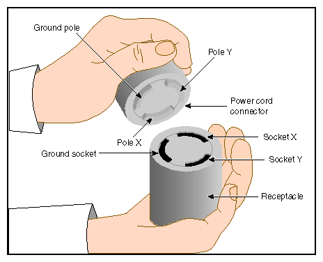
Ensure that a qualified technician installs the correct power receptacles. The SGI Origin 300 system with NUMAlink module uses one or two single-phase power receptacles. For North American sites, the single-phase receptacle is a 30-amp, 200- to 240-volt receptacle that has two phase sockets and one ground socket. For international sites, the single-phase receptacle is a 32-amp, 200-volt receptacle that has one phase socket, one neutral socket, and one ground socket.
For North American sites, use the following procedure to ensure that a single-phase power receptacle is properly wired:
Set the voltmeter to a high AC voltage range.
Check the voltage between socket X and socket Y (refer to Figure 2-1). The meter should read between 200 and 240 Vac.
Check the voltage between socket X and the ground socket. The meter should read approximately 120 Vac.
Check the voltage between socket Y and the ground socket. The meter should read approximately 120 Vac.
Check the voltage between the ground socket and an earth-ground location. The meter should read 0 Vac.
Change the voltmeter to a low-resistance setting.
Measure between the ground socket and an appropriate earth-ground location and ensure that resistance is less than 1 ohm.
Repeat Steps 1 through 7 for any additional single-phase power receptacles.
Caution: If a voltage reading is incorrect or if the resistance that is measured in Step 7 is more than 1 ohm, contact a site-approved electrician. Do not proceed with the installation procedure.
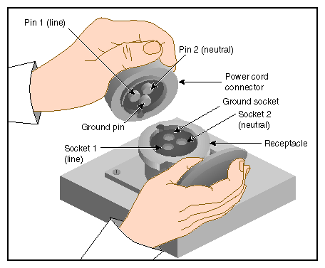
For international sites, use the following procedure to ensure that a single-phase power receptacle is properly wired:
Set the voltmeter to a high AC voltage range.
Check the voltage between socket 1 and socket 2 (refer to Figure 2-2). The meter should read between 200 and 240 Vac.
Check the voltage between socket 1 (line) and the ground socket. The meter should read between 200 and 240 Vac.
Check the voltage between socket 2 (neutral) and the ground socket. The meter should read approximately 0 Vac.
Check the voltage between the ground socket and an earth-ground location. The meter should read 0 Vac.
Change the voltmeter to a low-resistance setting.
Measure between the ground socket and an appropriate earth-ground location and ensure that resistance is less than 1 ohm.
Repeat Steps 1 through 7 for any additional single-phase power receptacles.
Caution: If a voltage reading is incorrect or if the resistance that is measured in Step 7 is more than 1 ohm, contact a site-approved electrician. Do not proceed with the installation procedure.
SGI Origin 300 systems arrive at the site in cardboard shipping crates. For a short-rack system, the documentation carton and the accessories carton are packed with the system. The documentation carton contains the system manuals as well as warranty and licensing information. The accessories carton contains the I/O, peripheral, and system cables and any additional connectors or tools that are required for a specific configuration. The PC, workstation, or terminal is shipped in a separate carton.
For a tall-rack system, the system documentation; accessories; and PC, workstation, or terminal arrive in separate cartons.
This section describes how to unload and transport the Origin 300 system with NUMAlink module to its designated location, as follows:
Unloading the equipment from the truck
Inspecting the shipping crate
Transporting the shipping crate
If your loading dock is the same height as the transportation vehicle, use a pallet jack to unload the system from the transportation vehicle. The pallet jack should have 48-in. tines or forks. Follow any instructions that are printed on the packing crates. If the loading dock is not the same height as the vehicle, you must provide a forklift or another approved method to unload the system. A platform or ramp may be used to obtain the desired level as long as the ramp incline does not exceed a ratio of one unit vertical to six units horizontal. For more information on site requirements, contact site planning by e-mail (site@sgi.com) or by telephone (1 715 726 2820).
| Warning: Use two or more people to prevent computer equipment from rolling off the transportation vehicle. Failure to do so could result in serious damage to the computer equipment. |
If your site does not have a loading dock, arrange for a forklift to unload the system from the transportation vehicle. Ensure that two or three people are available to help unload the equipment. Move all crates slowly and carefully.
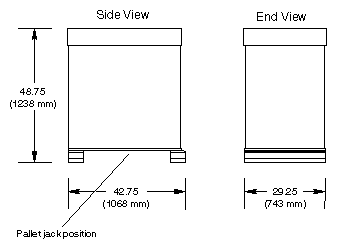
Figure 2-3 shows the lift openings and dimensions of a tall-rack shipping crate. This figure also shows where to position the pallet jack.
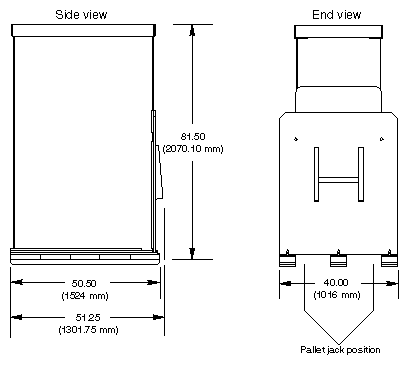
Figure 2-4 shows the lift openings and dimensions of a short-rack shipping crate. This figure also shows where to position the pallet jack.
After the system is unloaded from the truck, follow these steps before you unpack it:
Ensure that the crates and cartons arrive unopened.
Inspect the shipping crate for signs of external damage such as dents, holes, crushed corners, and water marks.
Ensure that the tilt watch has not been tripped.
If the crate is damaged, file a damage claim with the carrier immediately. In addition, notify your local Customer Support Center (CSC) for any missing, incorrect, or damaged items.
CSC contact information is provided at the following URL: http://www.sgi.com/support/supportcenters.html
Use a pallet jack with forks that are 48 in. (122 cm) long or longer to transport the shipping crate to the designated location. Refer to Figure 2-3 and Figure 2-4 for the crate dimensions and location to position the pallet jack. For system weight and dimensions, contact site planning by e-mail (site@sgi.com) or by telephone (1 715 726 2820).
If the crate does not fit through all access doors, you may need to partially disassemble the crate.
| Caution: If the system shipping or storage environment is significantly colder than the environment in which it will be installed [40 degrees F (22 degrees C) or greater disparity], leave the rack in its shipping crate for at least 24 hours at room temperature before you start the installation. This acclimation prevents damage to the equipment that could result from thermal shock and condensation. |
Now that you have unloaded the system from the truck and have transported it to its designated location, you are ready to remove the system from the shipping crate. This section provides installation instructions for short-rack and tall-rack systems.
| Warning: Be careful when you unpack and move the short-rack system. Ensure that the rack remains on a level surface and that the rack weight remains evenly distributed across the four casters. If you must lift the casters over an obstacle, such as a door threshold, use proper lifting techniques and employ a minimum of two people. |
| Caution: Do not subject the rack to any unnecessary shocks or vibration while you unpack and install the system. |
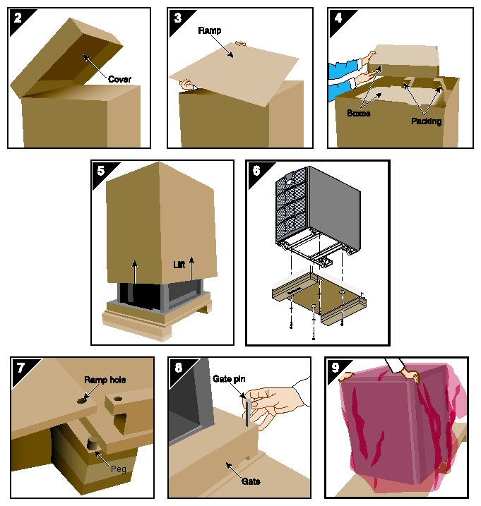
Refer to Figure 2-5 as you follow these steps; the numbered illustrations correspond to the numbered steps.
Ensure that the temperature of the rack is acclimated to the environment in which you are installing it.
Remove the crate cover.
Lift the ramp out of the crate and set it aside.
Remove the documentation carton, accessories carton, and cardboard packing material.
Lift the sidewalls of the crate up and over the system.
Remove the four bolts that secure the rack to the crate. You must reach underneath the crate and feel for the bolts.
Align the holes in the edge of the ramp with the pegs in the base of the crate. Ensure that the ramp is secure.
Remove the gate pins from the left and right ends of the gate. Then remove the gate.
Pull the rack down the ramp.

Warning: The maximum weight of the short rack is 488 lbs (221 kg). Use caution when you roll the rack down the ramp.
| Warning: In its maximum configuration, a tall-rack system weighs approximately 1,130 lb (512.56 kg). Use caution when you unpack and move this rack. Ensure that the rack remains on a level surface and that the rack weight remains evenly distributed across the four casters. |
To unpack a tall rack, you will need the following tools: extension, 6-inch, 3/8-in. drive; 13-mm standard 3/8-in. drive socket; and ratchet, reversible, 3/8-in. drive.
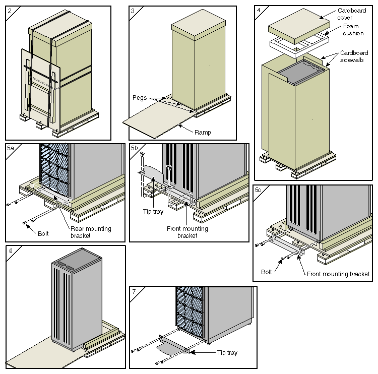
Refer to Figure 2-6 as you follow these steps; the numbered illustrations correspond to the numbered steps.
Ensure that the temperature of the rack is acclimated to the environment in which you are installing it and that the system crate is in a stable, upright position.
Remove the bands that secure the crate.
Note: Brace the wooden ramp as you remove the horizontal band that surrounds the crate and the wooden ramp. The ramp moves freely after you remove this band. Place the ramp so that the three holes in the edge of the ramp align with the pegs in the base of the pallet deck.
Remove the cardboard cover, the two cardboard sidewalls, and the foam cushion.
Remove the bolts that secure the rack to the pallet deck.
Remove the top four bolts from the rear mounting bracket; do not remove the bottom bolts.
Remove the four bolts that secure the front mounting bracket and tip tray to the bottom of the pallet deck. Set the tip tray aside.
Remove the top four bolts from the front mounting bracket. Set the mounting bracket aside.
Use two people to roll the rack out of the crate and down the ramp.
Warning: Use extreme caution when you roll the tall rack down the ramp. Personal injury and system damage could result if the rack becomes unbalanced or gains too much momentum when it rolls down the ramp. Bolt the tip tray to the front of the rack before you move the rack to its designated location. This tray prevents the rack from tipping while you move that rack.
| Caution: To avoid ESD damage to the electronic components, be sure to position the rack before you remove the ESD bag that covers the rack assembly. |
Grasp the rear of the rack and roll the rack to its designated location.
Remove the ESD bag.
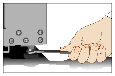
If you are installing a tall rack, adjust the leveling bolts, as shown in Figure 2-7, until the rack is level.
Ensure that the circuit breaker on the power distribution unit is in the OFF (0) position. Then connect the power cord to a grounded power outlet. Plugging in the power cord grounds the rack.
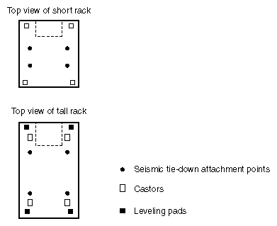
Secure the rack with seismic tie-downs if you are installing the system in an earthquake zone.
Note: Tall and short racks have four threaded holes that are located at the bottom of the rack (refer to Figure 2-8). Use these holes to secure the seismic tie-downs. SGI does not supply the seismic tie-downs.
| Caution: To avoid ESD damage to the electronic components, be sure to position the racks before you remove the ESD bags that cover the rack assemblies. |
Grasp the rear of each rack and roll the rack to its designated location. Rack 002 contains the Myrinet-2000 switch.
Remove the ESD bags.
Adjust the leveling bolts of rack 001, as shown in Figure 2-7, until the rack is level.
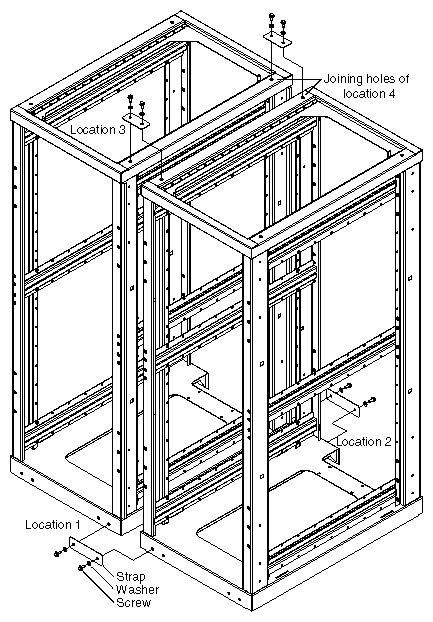
Using the leveling bolts of rack 002, adjust rack 002 so that the joining holes of rack 002 align with the joining holes of rack 001. Refer to Figure 2-10.
Using the provided straps, screws, and washers; bolt the racks together in the four designated locations shown in Figure 2-10.
If your system has additional racks, repeat Steps 4 and 5 until all of the racks are bolted together.
Ensure that the circuit breakers on the power distribution units are in the OFF (0) position. Then connect the power cords to grounded power outlets. Plugging in the power cords ground the racks.
Secure the racks with seismic tie-downs if you are installing the system in an earthquake zone.
Note: Tall racks have four threaded holes that are located at the bottom of the rack (refer to Figure 2-8). Use these holes to secure the seismic tie-downs. SGI does not supply the seismic tie-downs.