This chapter describes the following system configurations:
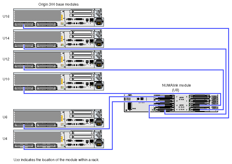
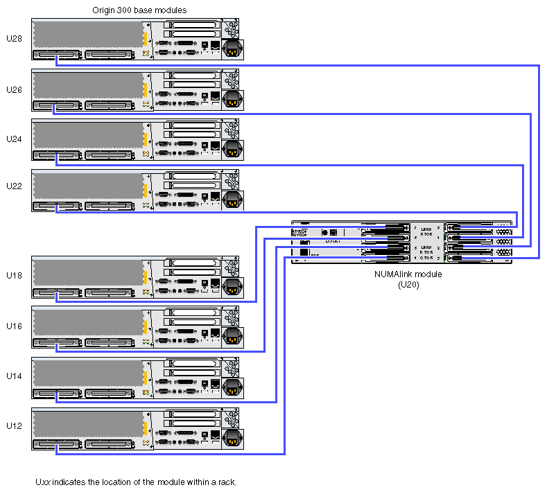
In a tall rack, the SGI Origin 300 system with NUMAlink module consists of two to eight Origin 300 base modules. A short rack can consist of two to six base modules. When only two base modules are present in the system, they reside in the locations that are directly below the NUMAlink module. For example, when the NUMAlink module resides in location U20 (tall rack), the two base modules reside in locations U18 and U16. When the NUMAlink module resides in location U8 (short rack), the two base modules reside in locations U6 and U4.
| Note: The global master is the Origin 300 base module that resides in the lowest location in the rack. |
Additional base modules are added to the rack by alternating between the top and bottom portions of the rack. For example, the additional base modules can be added to the rack in the following order:
The third base module is placed in location U22 (tall rack) or U10 (short rack).
The fourth base module is placed in U24 (tall rack) or U12 (short rack).
The fifth base module is placed in U14 (tall and short racks).
The sixth base module is placed in U12 (tall rack) or U16 (short rack).
The seventh base module is placed in U26 (tall rack).
The eighth base module is placed in U28 (tall rack).
The Origin 300 base modules communicate with each other via the NUMAlink module. Figure 4-1 shows the compute configuration for the short rack.
Figure 4-2 shows the compute configuration for the tall rack.
The control system for the SGI Origin 300 system with NUMAlink module manages power control and sequencing, provides environmental control and monitoring, initiates system resets, and stores identification and configuration information. The SGI Origin 300 system with NUMAlink module has two levels of control:
L1: module-level controller. The L1 controller is designed into all modules except the TP900 storage module; controller function varies slightly by module. The L1 controllers are not configurable.
L2: rack-level controller. The L2 controller enables remote maintenance. It controls resource sharing and the L1 controllers in the system, and maintains controller configuration and topology information. The L2 controller resides in the top portion of the rack.
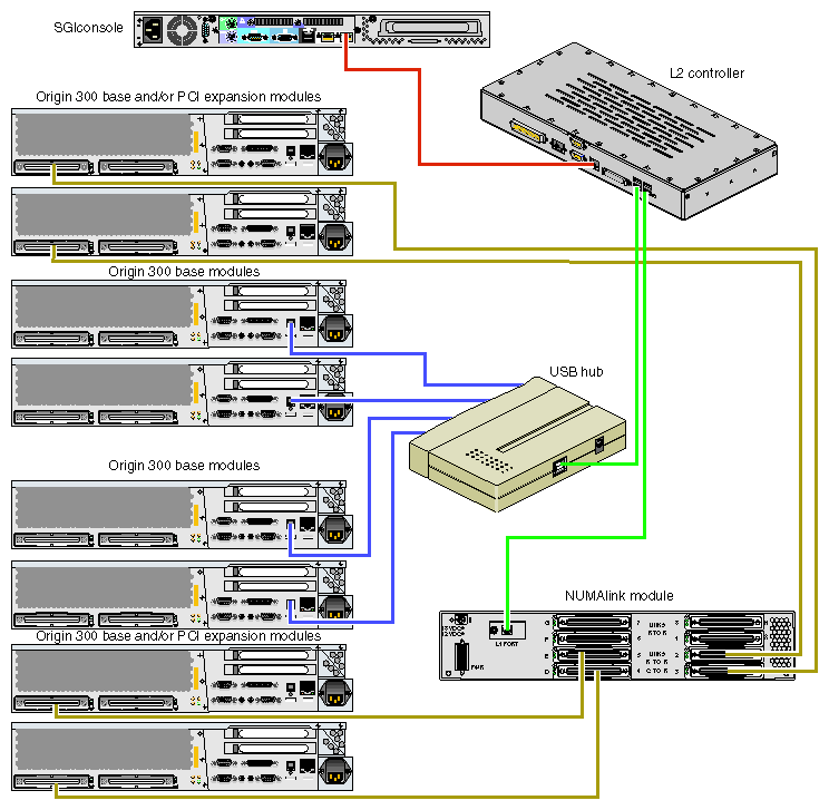
The L1 controllers within the system communicate with the L2 controller via the NUMAlink module or via a USB hub (refer to Figure 4-3). The Origin 300 base modules and/or PCI expansion modules that connect to ports 2, 3, 4, and 5 of the NUMAlink module communicate with the L2 controller via the USB signals of these NUMAlink ports. The Origin 300 base modules that connect to ports 1, 6, 7, and 8 of the NUMAlink module communicate with the L2 controller via a USB hub.
You can access the L1 and L2 controllers via the system console. Refer to Appendix C, “System Controller Commands” for L1 and L2 controller commands.
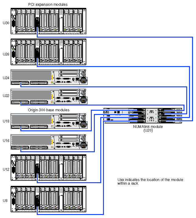
Each Origin 300 base module has two PCI slots; however, you can increase the number of PCI slots by adding PCI expansion modules to the system. The Origin 300 system with NUMAlink module supports one or two PCI expansion modules in a short rack and as many as four PCI expansion modules in a tall rack. The following rules indicate how many PCI expansion modules you can add to your tall-rack system:
You can add one PCI expansion module to a system that contains two to seven base modules.
You can add two PCI expansion modules to a system that contains two to six base modules.
You can add three PCI expansion modules to a system that contains three to five base modules.
You can add four PCI expansion modules to a system that contains four base modules.
In a tall rack, the PCI expansion modules reside directly above and below the NUMAlink module and the Origin 300 base modules. For example, two PCI expansion modules reside in the highest available locations in the bottom section of the rack (U8 and U12). The other two PCI expansion modules reside in the first available locations in the top portion of the rack (for example, U26 and U30).
The following rules indicate how many PCI expansion modules you can add to your short-rack system:
You can add one PCI expansion module to a system that contains two to four base modules. Valid locations for this module are U10, U12, or U14.
You can add one or two PCI expansion modules to a system that contains two base modules. These modules reside in locations U10 and U14.
The Origin 300 base modules and L2 controller communicate with the PCI expansion modules via the NUMAlink module. The PCI expansion modules connect to the NUMAlink module via ports 2, 3, 4, and 5, which are the ports that carry NUMAlink and USB signals (refer to Figure 4-4).
Each Origin 300 base module contains two disk-drive bays; however, you can add additional storage to the system. The TP900 storage module provides a SCSI JBOD solution for the Origin 300 system with NUMAlink module. The TP900 can be configured as follows:
For a single-port configuration (eight drives), one I/O module is required (bay 1/1).
For a dual-port configuration (four drives per port), use two I/O modules.
Populate all disk drive bays with a
disk drive or a filler plate.Install the drives in the following order:
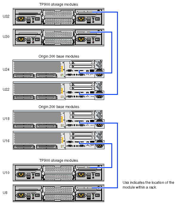
The TP900 storage module resides in the Origin 300 rack. The placement of the storage modules within the rack depends on the number of other modules in the rack. The following rules apply:
In the short rack, place the TP900 in the highest available location of the rack. For example, if the short-rack system contains two base modules, one NUMAlink module, and one PCI expansion module, place the TP900 storage module in U16. If you want to add another storage module to the system, place it in U14.
In the tall rack, the placement of the TP900 storage module alternates between the top and bottom portions of the rack; the storage modules do not have to be grouped together.
In the bottom portion of the rack, place the first TP900 module in location U10. If this location is not available, place the TP900 in the next available location in the bottom portion of the rack (for example, U8).
Place the second TP900 in location U30. If this location is not available, place the TP900 in the next available location in the top portion of the rack (for example, U32).
Continue to alternate between the top and bottom portions of the rack as you place the TP900 modules in the system.

Note: Locations U12 through U29 are reserved for the NUMAlink, Origin 300 base, and PCI expansion modules. If you need additional rack space for storage modules and space is available within U12 through U29, you may place additional TP900 modules within this reserved space.
The Origin 300 base modules can connect to the TP900 storage module via the SCSI port connector on the rear of the Origin 300 base module or via a low-voltage differential (LVD) PCI card (refer to Figure 4-5).
The standard power component of an Origin 300 with NUMAlink module system is a power distribution unit (PDU). A second PDU or a power strip might also exist in the rack. The power strip exists when the system requires 11 to 15 power receptacles. The second PDU exists when the system requires more than 15 power receptacles.
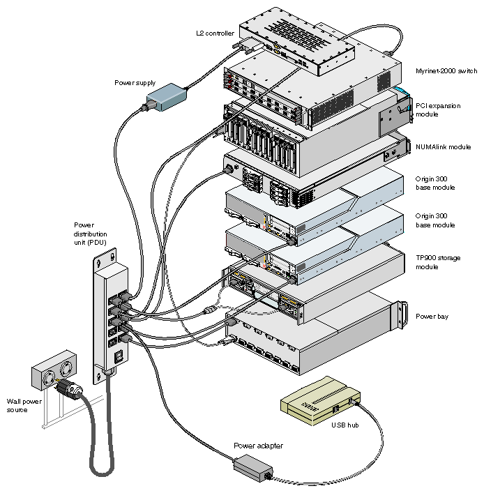
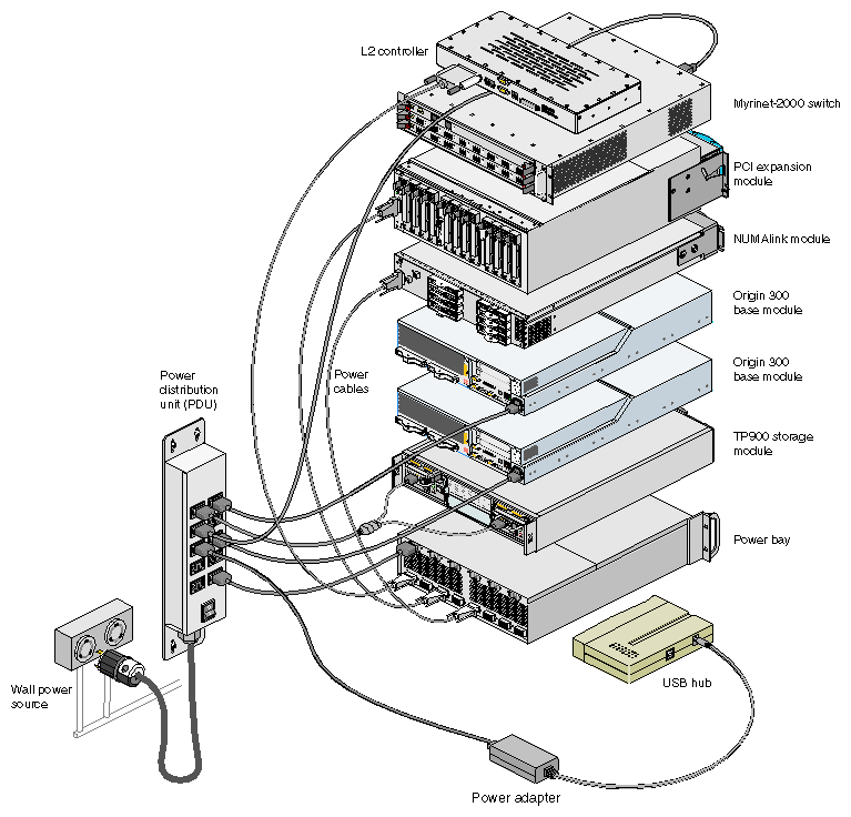
The PDU inputs AC voltage from an external power receptacle and outputs AC voltage to the Origin 300 base modules, AC-powered NUMAlink module, TP900 storage modules, power adapter of the USB hub, power bay module, Myrinet-2000 switch, L2 controller power supply, and power strip.
| Note: In a system that contains an AC-powered NUMAlink module, the L2 controller receives power from a power supply. This power supply receives AC voltage from a PDU or power strip and converts the voltage to 48 Vdc, which is the input voltage that the L2 controller requires. In a system that contains a DC-powered NUMAlink module, the L2 controller receives the 48 Vdc from a power bay. |
In addition to the PDUs and power strip, a system that has a DC-powered NUMAlink or PCI expansion module contains one power bay module. The power bay module, which resides in U1 of the short and tall racks, converts AC voltage to 48 Vdc and 12 Vdc standby voltage and outputs this voltage to the NUMAlink module, the PCI expansion modules, and the L2 controller. The power bay contains two power supplies, which reside in locations 5 and 6 of the power bay.
| Note: When a system that contains a DC-powered NUMAlink module has four PCI expansion modules, the power bay contains three power supplies. The third power supply resides in location 4 of the power bay. |
| Note: An AC-powered NUMAlink module system requires a power bay only when it contains a PCI expansion module. |
Figure 4-6 illustrates the power configuration of an Origin 300 system that contains an AC-powered NUMAlink module. Figure 4-7 illustrates the power configuration of a system that contains a DC-powered NUMAlink module.
