Much of the ImageVision Library implementation consists of image-processing algorithms, or operators. An operator applies its algorithm to the image data encapsulated in an ilImage object. To maximize the efficiency of the computation required to perform such an operation, IL uses the demand-driven execution model discussed in Chapter 2, “The ImageVision Library Foundation.”
This chapter explains how to use each of the operators defined by IL. “Implementing an Image Processing Operator” explains how you can implement your own image processing algorithm as an IL operator.
This chapter contains the following major sections:
“Image Processing Operators Provided with IL” describes the set of approximately 70 image processing operators implemented in IL.
“Defining a Region of Interest” explains how to mask out portions of an image and restrict processing to a desired area.
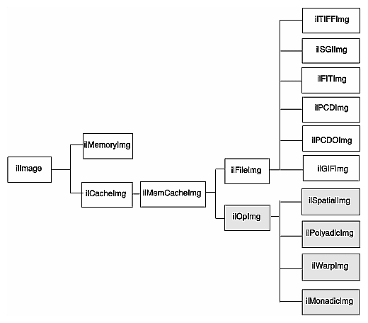
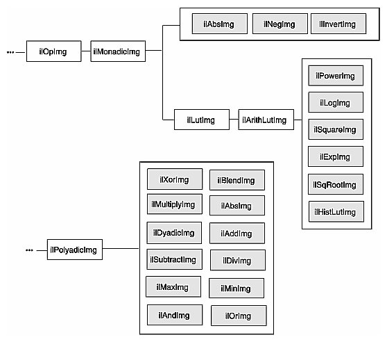
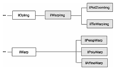
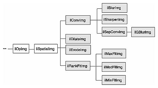
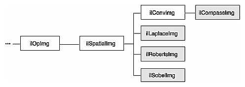
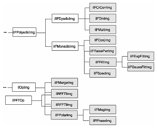
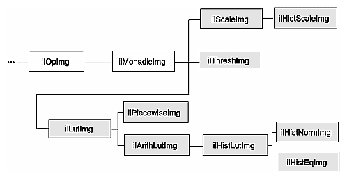
IL classes covered in this chapter are mainly those that derive from ilOpImg. The relevant portion of IL inheritance hierarchy is shown shaded in Figure 4-1.
The ilOpImg class defines the basic support for all operator classes. It provides functions for setting attributes, accessing data, setting bias and clamp levels, and propagating attributes down an operator chain. Most of these functions are declared protected, so while they are available for use in a subclass's implementation, they are not available (or needed) directly. ilOpImg defines only three sets of public functions:
ilStatus setBias(double biasVal = 0); double getBias(); ilStatus setClamp(iflDataType typ=iflDataType(0)); ilStatus setClamp(double min, double max); int getValidTypes(); int getValidOrders(); |
Some operators take a bias argument in their constructors and use it in their image processing algorithms. This bias value is discussed in the sections describing the relevant operators in the remainder of this chapter. In general, bias is a constant value added to each pixel luminance value to make it scale correctly. If, for example, the raw pixel luminance covers values between 100 and 200, some operators are able to scale the luminance values over the entire depth of pixel luminance values, for example, 0 - 255. When you scale the luminance values in this way, you need a bias value that adjusts the initial, raw luminance value, 100, in this example, to zero.
The setClamp() functions allow you to set values that pixels are clamped to if underflow or overflow occurs. Not all operators allow the clamp values to be modified, so you need to check that the returned status is not ilUNSUPPORTED if you are assuming you have changed the values. The first version of setClamp() sets the clamp values to be the minimum and maximum values allowed for the data type. The default value of typ means to use the a single bit image type. The second version allows you to specify actual clamp values. You will not generally need to use either of these functions since most operators handle overflow and underflow conditions appropriately.
All operators that alter the data range of their inputs compute the worst case minimum and maximum pixel values to ensure that the processed data can be displayed. For example, if you multiply two images and then display the result, you can easily end up with pixel data that is all black. To solve this problem, ilMultiplyImg automatically computes the worst case minimum and maximum values. When the data is displayed using ilDisplay, the data is automatically scaled between these values (or those allowed by the display) so that a meaningful display is produced.
The ilOpImg protected functions that implement these features are
double getInputMin(int idx=0); double getInputMax(int idx=0); double getInputScaleMin(int idx=0); double getInputScaleMax(int idx=0); |
The getInput functions return the minimum and maximum luminance values of the input images. The getInputScale functions return the minimum and maximum luminance values of the output image.
This section discusses all the operators provided with IL. they are grouped functionally as listed below:
“Color Conversion and Transformation” describes operators that convert an image from one color model to another.
“Arithmetic and Logical Transformations” describes operators that perform pixelwise arithmetic or logical computations.
“Geometric Transformations” describes operators that warp, rotate, and zoom (magnify or minify) an image.
“Spatial Domain Transformations” describes operators that transform an image in the spatial domain—for example, by sharpening, blurring, convolving, or rank filtering it in the spatial domain.
“Edge Detection” describes gradient operators such as compass, Laplace, Roberts, and Sobel.
“Frequency Domain Transformations” describes operators that incorporate forward or inverse Fourier transforms and frequency-domain filters.
“Generation of Statistical Data” describes the operator that computes the histogram, mean, and standard deviation of an image.
“Radiometric Transformations” describes operators that perform radiometric transformations such as histogram normalization and thresholding.
“Combining Images” describes operators that blend, merge, or combine two images.
“Constant-valued Images” describes an image class that returns a constant value for all data accesses.
“Using a Null Operator” describes an operator that performs a “null” operation.
IL provides several operators that perform color conversions and color transformations of IL images. These operators can be summarized as follows:
The ilColorImg operator converts an existing image from any IL-supported color model to a requested color model. (See “Color Model” for a description of the color models supported by IL.)
Several operators, derived from ilColorImg, convert an existing image to one of the more commonly used color models: CMYK, grayscale, HSV, and RGB.
The ilFalseColorImg operator converts an image from one multispectral color model to another.
The ilSaturateImg operator provides a mechanism to transform the color saturation of an image.
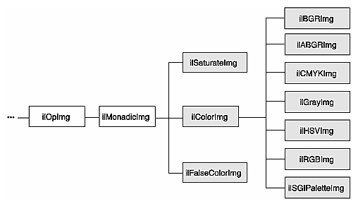
These color conversion and transformation operators are described in the following paragraphs. Their positions in IL inheritance hierarchy are shown in Figure 4-2.
The base class for the color conversion operators, ilColorImg, defines the generic support for performing color conversions on image data. It converts data from any supported color model to any other supported color model, except multispectral.
ilColorImg(ilImage* img, iflColorModel cm); |
For example, the following code converts an iflRGB image (theimg) to one whose color model is iflYCC.
ilColorImg(ilImage* theimg, iflColorModel iflYCC); |
The ilColorImg class is not normally used directly to do color-model conversion. Instead, use derived classes. Each of the six classes derived from ilColorImg performs a specific conversion. The algorithms used to perform the various conversions are detailed in the respective reference pages. The six derived classes are summarized below:
ilABGRImg converts data to the ABGR color model used by Silicon Graphics' framebuffer.
ilRGBImg converts an image to RGB.
ilCMYKImg converts data to the CMYK color model. This color model is used primarily as an output format for color printers.
ilGrayImg converts an image to minBlack.
ilHSVImg converts to the HSVcolor model.
ilRGBImg converts an image to the iflRGB color model.
ilSGIPaletteImg converts data to the iflRGBPalette color model. This color model is suitable for data that is to be displayed in a color-mapped window.
Using any of these derived classes is simple since the only public member function most of them define is a constructor. To convert an ilImage, call the constructor for the desired color model and supply as an argument a pointer to the ilImage to be converted. For the following example, assume that theImg has already been created and that it uses any one of the supported IL color models:
ilCMYKImg* cnvrtdImg; cnvrtdImg = new ilCMYKImg(theImg); |
In this example, the constructor for the ilCMYKImg class returns a pointer to an ilCMYKImg, which produces image data converted to the CMYK color model. Similarly, the constructors for any of the derived classes—ilABGRImg, ilCMYKImg, ilGrayImg, ilHSVImg, ilRGBImg, or ilSGIPaletteImg—return a pointer to an object of that class, which produces converted image data. that is really all there is to it.
If you want to convert to the color models for which there is no derived class (iflRGBA, iflCMY, ilBRG or iflYCC), use the ilColorImg operator.
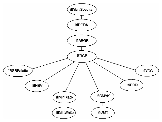
If an operator image has two or more inputs with different color models, the color model of the resulting image depends on the color models of the input images. IL converts the color models of the input images to a common color model before performing the operation. The resulting image has this color model. You can use the diagram in Figure 4-3 to determine how IL determines the common color model. Just find the nodes for the input images and follow the paths from these nodes to a common node. This nodes determines the color model of the resulting image. For example, if the color models of two inputs to an operator are iflHSV and iflYCC, the color model of the resulting image is iflRGB.
The ilFalseColorImg operator performs false coloring of multispectral images. It accomplishes this by computing the weighted sum of the input channels for each channel of the resulting false-color image. The constructors for ilFalseColorImg, except the NULL constructor, or take a pointer to the input image and the arguments that define the conversion algorithm:
ilFalseColorImg();
ilFalseColorImg(ilImage *img, int numColumns, int numRows,
    const float* xformMatrix, const float* bias=NULL);
|
The conversion is defined by the transformation matrix, xformMatrix. This matrix has dimensions numColumns x numRows. Each row of this matrix defines a set of weights used to produce one channel of the output. Each weight is multiplied by the pixel values in the corresponding input channel, and the weighted sum forms the output channel. The conversion may also include a bias vector, bias. This vector contains a constant value for each input channel that is added to each input value before it is weighted. Thus, the transformation equation for each channel of the output image is:
where C and R are numColumns and numRows, respectively.
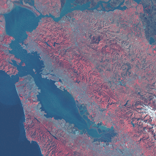
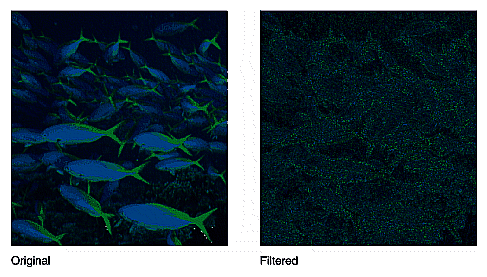
An image transformed by ilFalseColorImg appears in Figure 4-4.
This operator performs a color saturation of its input. If the input color model is not RGB, the input is first converted to RGB. The constructor for ilSaturateImg takes a pointer to the input image and an initial saturation value:
ilSaturateImg(ilImage* img=NULL, float sat=1); |
The transformation is defined as:
Equation 1
Equation 2
Equation 3
Equation 4
You can set the saturation value interactively with setSaturation():
void setSaturation(float saturation); |
The current value of the saturation factor can be queried with getSaturation():
float getSaturation(); |
A value of zero completely desaturates the image (equivalent to ilGrayImg), a value of one leaves the image unchanged, and values greater than one increase the color saturation of the image. Output values are clamped to the minimum and maximum values of the operator image, which by default are simply inherited from the input.
There are numerous IL operators that perform pixelwise arithmetic transformations of image data. Some of these require two input images—for example, to add them together—while others perform computations on a single image's data, such as determining the absolute value. In the inheritance hierarchy shown in Figure 4-5, operators that inherit from ilPolyadicImg take two images as inputs and those that derive from ilMonadicImg take only one.
When using one of the dual-input operators, you might want to use an ilConstImg as one of the inputs. An ilConstImg returns the same value for all of its pixels, so you can use it to multiply each of an image's pixels by a constant value, for example. For more information on how to create an ilConstImg, see “Constant-valued Images”.
The single-input arithmetic operators are listed in Table 4-1, along with the operation they perform on each pixel of image data and the pixel data types each operation can produce. The last five operators in Table 4-1 (ilSquareImg, ilSqRootImg, ilExpImg, ilPowerImg, and ilLogImg) descend directly from ilArithLutImg. The ilArithLutImg abstract class optimizes the performance of operators that derive from it by pulling precomputed square, square root, exponent, power, and log values from a lookup table. This is much more efficient than computing values on a per-pixel basis.
The ilArithLut class in turn inherits from ilLutImg. Consequently, the last five operators in Table 4-1 inherit the ability to be accelerated further in the CPU or in specialized graphics hardware. See “Radiometric Transformations” and “Using Hardware Acceleration” for details about ilArithLutImg and hardware acceleration, respectively.
Table 4-1. Single-input Arithmetic Operators and Their Valid Output Data Types
Operator | Operation Performed | Valid Data Types | |
|---|---|---|---|
ilAbsImg | iflUChar, iflUShort, iflULong, iflFloat, iflDouble | ||
ilNegImg | any signed data type[a] | ||
ilInvertImg | iflBit, iflChar, iflUChar, iflShort, iflUShort, iflLong, iflULong | ||
(pixelvalue)2 | any type except iflBit | ||
any type except iflBit | |||
ilExpImg [b] | any type except iflBit | ||
any type except iflBit | |||
any type except iflBit | |||
[a] iflChar iflShort, iflLong, iflFloat, and iflDouble are the signed data types. [b] These operators allow you to apply scale and bias values to the pixelvalue, so that it becomes scale*pixelvalue+bias. | |||
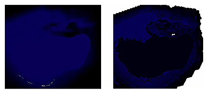
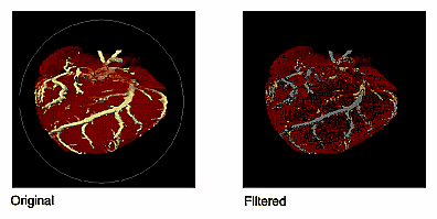
An example of processing by an arithmetic operator is given in Figure 4-6, which shows an original image constructed from simulation data processed with ilNegImg.
The only public member function defined in ilAbsImg, ilNegImg, ilInvertImg, ilSquareImg, and ilSqRootImg is a constructor that takes a single argument, the input image. Thus, to include any of these operators in a chain, you simply call its constructor and pass, as the argument, a pointer to the input ilImage. In this example, assume that inputImg is a pointer to an already existing ilImage:
ilAbsImg* someAbsImg = new ilAbsImg(inputImg); |
The constructors for the ilAbsImg, ilNegImg, ilInvertImg, ilSquareImg, and ilSqRootImg classes all return a pointer to the operator image.
The constructors for the remaining three classes—ilExpImg, ilPowerImg, and ilLogImg—take three additional arguments, all of type double. The second argument for each of these constructors specifies base or power, the third specifies scale, and the fourth bias.
ilExpImg(ilImage* inImg = NULL, double expBase=0,
              double scl=1., double bs=0.);
ilPowerImg(ilImage* inImg = NULL, double pow = 2,
              double scl=1., double bs=0.);
ilLogImg(ilImage* inImg = NULL, double logBase=0,
              double scl=1., double bs=0.);
|
The ilExpImg, ilPowerImg, and ilLogImg classes define a function for setting the value of the second parameter after the operator is created, so that you can dynamically alter the computation:
void setBase(double expBase=0); // for ilExpImg void setPower(double power=2); // for ilPowerImg void setBase(double logBase=0); // for ilLogImg |
As their names suggest, the dual-input operators ilAddImg, ilSubtractImg, ilMultiplyImg, and ilDivImg perform standard arithmetic computations—addition, subtraction, multiplication, and division of two images. The constructors for each of these classes take as arguments pointers to the two input images, which can be different sizes but must have the same number of channels. If they are different sizes, by default the output image is the larger of the two sizes; the smaller input image is padded with its fill value, and then the operator performs its computation on corresponding pixels in the two images. You can explicitly set the desired output size with ilImage.setSize().
You may also offset one image with respect to the other using the following ilPolyadicImg methods:
void setOffset(int x, int y, int z = 0, int input = 0); void getOffset(int &x, int &y, int &z, int input = 0); |
setOffset() offsets the first image with respect to the second by x, y, and z if input is 0. If input is 1, the second image is offset with respect to the first. getOffset() queries the dual-input operator for its offsets. If input is 0, the offset of the first image relative to the second is given; if input is 1, the offset of the second image relative to the first is given.
Here are the constructors for the dual-input operators:
ilAddImg(ilImage* in1 = NULL, ilImage* in2 = NULL,
          double bias=0);
ilSubtractImg(ilImage* in1 = NULL, ilImage* in2 = NULL,
          double bias=0);
ilMultiplyImg(ilImage* in1 = NULL, ilImage* in2 = NULL);
ilDivImg(ilImage* in1 = NULL, ilImage* in2 = NULL, ckDiv=1);
|
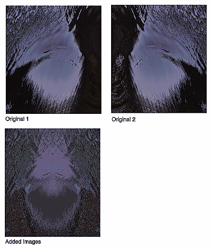
ilAddImg adds the bias value to the sum found by adding the corresponding pixels of in1 and those of in2. The ilSubtractImg operator subtracts the corresponding pixels of in2 from every pixel of in1 and then adds the bias value. ilMultiplyImg multiplies the pixels in the two input images, and ilDivImg divides the pixels of in1 by the corresponding pixels of in2. All of these operators can produce an image containing any data type except iflBit. An example using ilAddImg appears in Figure 4-7. The two original images appear as well; one is the flipped version of the other.
The ckDiv argument for ilDivImg's constructor specifies whether the operator should check for division by zero. By default, it does check and responds as described below:
If the divisor is zero and the dividend is positive, the quotient is set to the maximum value possible for the final image's data type.
If the divisor is zero and the dividend is negative, the quotient is set to the minimum value possible for the final image's data type.
Zero divided by zero produces a zero.
You can use setCheck() to change whether this check is made.
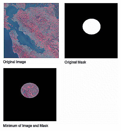
The two classes ilMaxImg and ilMinImg compare each corresponding pixel in the two input images and select the greater or the lesser value, respectively. Their constructors take pointers to the two input images as arguments. These input ilImages must have the same number of channels. The output image can contain any data type except iflBit. (There are also simple, in-line functions defined in the header file il/ilMinMax.h that compare two values and return the greater or the lesser one. See “Minimum and Maximum Comparisons” for more information about these functions.) An example of using ilMinImg appears in Figure 4-8. Two original images are shown, followed by the image that results if you apply ilMinImg to these images.
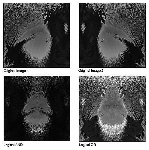
Similarly, the logical-operator classes—ilAndImg, ilOrImg, and ilXorImg—perform their computations (logical AND, OR, and exclusive-OR) by combining each corresponding pixel in the two input images. The constructors for these classes take pointers to the two input images as arguments. The input ilImages must have the same number of channels; the output image can contain any of the following data types: iflChar, iflUChar, iflShort, iflUShort, iflLong, or iflULong. Figure 4-9 shows an example of using ilAndImg and ilOrImg on the original images from Figure 4-7.
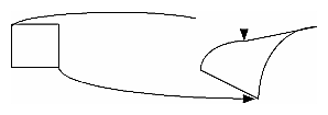
The heart of a geometric transformation, or warp, is the algorithm that maps output image coordinates to input coordinates. (See Figure 4-10.) The general support for such transformations is encapsulated in the abstract class, ilWarpImg. Classes that derive from ilWarpImg— ilTieWarpImg, and ilRotZoomImg—implement specific warping algorithms;. These algorithms are most efficient for images that are relatively square.
The warping classes are shown in Figure 4-11 and discussed in the following sections.
The ilWarpImg class, from which ilTieWarpImg, and ilRotZoomImg derive, performs up to a two-dimensional, seventh-order warp. The output image space is mapped to the input image space with a transformation defined by two sets of polynomials (which can be up to seventh order), one for the x-dimension and one for the y-dimension. Since the coefficients for the polynomials are not always integers, the addresses computed for the output space sometimes contain fractional components. Therefore, a resampling method must be applied to convert these fractional addresses into meaningful pixel locations.
To use ilWarpImg, you must choose a resampling algorithm and specify the coefficients of the warping polynomials. The constructor takes as its arguments a pointer to the input image and a constant that corresponds to a resampling method:
ilWarpImg(ilImage* img=NULL, ilResampType rs=ilNearNb,
    ilWarp* warp=NULL);
|
The ilResampType enumerated type is defined in the header file il/iflDataTypes.h and shown in “Resampling Methods”. It has these six members:
ilNearNb (nearest neighbor)
ilBiLinear
ilBiCubic
ilMinify
ilUserDef (for a resampling algorithm you implement)
If you choose a bicubic resampling method, you can use setBicubicFamily() to fine-tune its algorithm.
ilWarpImg performs output-driven image warps. It uses the abstract. helper class, ilWarp, to define the specific nature of a given warp. An image of any data type may be given as input. The proper data conversions will be performed to ensure output is one of the following valid data types: ilUChar, ilUShort, ilShort or ilFloat.
ilWarpImg is a cached, image operator. It may be linked into operator chains.
The ilWarpImg class supports five built-in resampling methods:
nearest neighbor
bi-linear (the default)
bi-cubic interpolation
filtered minification (ilMinify)
auto resampling
The resampling type can be altered with setResampType(). ilWarpImgSetResampType(). Support for user-defined resampling methods is also provided by the setResampFunc() function.
Nearest neighbor is the fastest method, but produces the lowest quality result. This method merely copies the value of the input pixel that is closest to the computed address. It is most useful when performance is more important than image quality, as for instance when the warp is under interactive control by a human. When the warping parameters have been adjusted to satisfaction, the final output might be produced with the bi-linear or bi-cubic method.
The bi-linear method interpolates over a 2x2 neighborhood around the computed input address, using a simple weighted average. This method is somewhat slower than nearest neighbor, but produces a much higher quality result.
The bi-cubic method interpolates over a 4x4 neighborhood, using an interpolation kernel that approximates a two-dimensional bi-cubic spline. For a given (x, y) point, the interpolation is performed by first interpolating four lines starting at floor(y)-1 and ending at floor(y)+2; each line runs from floor(x)-1 and ends at floor(x)+2. The resulting values are then processed vertically to produce the resulting output point.
In order to speed up the processing, the cubic convolution co-efficients are precomputed to a 1/256 pixel accuracy and stored in a table. This provides more than adequate accuracy for geometric precision. The co-efficient generation is from equation (8) in the paper:
Mitchell, D. and A. Netravali, “Reconstruction Filters in Computer Graphics.” Computer Graphics, Vol. 22, No. 4, pp. 221-228.
The setBicubicFamily() function allows the B and C co-efficients of equation (8) in the cited paper to be defined, allowing a choice of various bicubic resampling.
Filtered minification is used when unaliased minification is desired. The input image is filtered and minified. The user can specify a filter or, if none is specified, a box filter is used. The size of the box filter, depends on the minification factor and it ensures that the entire input image is sampled. If the box filter or kernel is used, the operation can be speeded up by sub-sampling the kernel. By using the setMaxSamples() function, the number of image pixels are averaged to produce an output pixel can be set. So if the number of samples is set to 10, even when using a 5 x 5 kernel, only 10 image pixels used to compute the filtered result.
| Note: When specifying your own kernel, each zero value in the kernel results in one less multiply/add computation. So, sprinkling zeros around the kernel achieves sub- sampling. |
If you choose the ilMinify resampling method, you can use setMinifyKernel() to specify your own kernel instead of the default box (all 1s) kernel. In the default case, the kernel size is dynamically adjusted so that the entire input is sampled (that is, all the input image pixels are used to compute the output). If you use the default kernel, you can speed up the operation by using setMaxSamples() to set the number of input image pixels to be averaged to produce a single output pixel. For example, if you set the maximum number of samples to 10 and you are minifying by a factor of 8, thus necessitating the use of an 8 x 8 kernel, only 10 input pixels (instead of 64) uniformly interspersed throughout the 8 x 8 area are averaged to produce one output pixel.
To define your own resampling method, use setResampFunc() and pass in a pointer to your algorithm. The reference page for ilWarpImg explains what the supported algorithms are, which one you might want to use, and how to define your own algorithm.
You can dynamically change and retrieve the resampling method with setResampType() and getResampType(), which are inherited from ilWarpImg:
void setResampType(ilResampType rs); ilResampType getResampType(); |
Additionally, ilWarpImg lets you determine the amount of error allowed in a warp performed in graphics hardware with setAddressError(). Its one parameter, maxPixelsOff, determines by how many pixels the warped data may be incorrect. The previously set parameter can be retrieved with getAddressError():
void setAddressError(float maxPixelsOff); float getAddressError(); |
For backward compatibility, you can define the coefficients of the warping polynomial using the ilPolyWarpImg.setCoeff() function:
void setCoeff(const ilCoeff_2d& xcoeff, const ilCoeff_2d& ycoeff); |
You can query the ilWarpImg object for its coefficients with ilPolyWarpImg.getCoeff() and for the order of its polynomial with ilPolyWarpImg.getPolyOrder():
void getCoeff(ilCoeff_2d& xcoeff, ilCoeff_2d& ycoeff); int getPolyOrder(); |
The ilPolyCoeff2SD structure contains floating point numbers for the coefficients. It is defined in the header file il/ilPolyDef.h, as shown below:
struct ilPolyCoeff2D {
    float con,
        y, x,
        y2, xy, x2,
        y3, xy2, x2y, x3,
        y4, xy3, x2y2, x3y, x4,
        y5, xy4, x2y3, x3y2, x4y, x5,
        y6, xy5, x2y4, x3y3, x4y2, x5y, x6,
        y7, xy6, x2y5, x3y4, x4y3, x5y2, x6y, x7;
};
|
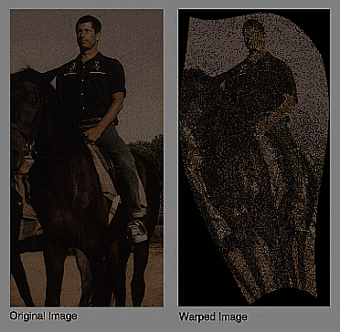
The ilTieWarpImg class performs a two-dimensional warp, but it does not allow you to specify the coefficients of the warping polynomial directly. Instead, you specify pairs of tie points in the input and the output images that should match after the image is warped as shown in Figure 4-12. The coefficients of the polynomial, which you can choose to be first- to seventh-order, are then computed from these tie points. The minimum number of pairs of points necessary to determine the coefficients of a polynomial of order ord is given by the formula:
Thus, you need to specify at least three pairs of points for a first-order polynomial, six pairs for a second-order, and so on.
The constructor for ilTieWarpImg takes the same arguments as that for ilWarpImg. After creating an ilTieWarpImg operator, you must specify the tie points from which the warping polynomial is computed. For this, use setTiePoints):
void setTiePoints(const iflXYfloat* uv,
    const iflXYfloat* xy, int n);
|
This function takes pointers to arrays of n tie points in the input image (xy) and the output image (uv) and computes the polynomial's coefficients. (The data type iflXYSfloat is defined in the header file il/iflCoord.h as an (x, y) coordinate pair of data type float.) The function isWellDefined() can be used to check if the polynomial coefficients can be computed from the specified tie points. If the polynomial is successfully computed, one is returned; if not, zero is returned. Before you call setTiePoints(), you might want to set the order of the polynomial that will be computed by calling setPolyOrder() and passing in 1, 2, 3, 4, 5, 6, or 7 as the desired order. If you do not explicitly set the order, a first-order polynomial is used. The function getPolyOrder() returns the order of the warping polynomial.
To move the tie points, use moveTiePoint(), defined as follows:
ilStatus moveTiePoint(float u, float v, float x, float y, int idx); |
ilWarpImg defines functions (which ilTieWarpImg and ilRotZoomImg inherit) that, given a point in the input (or output) image, compute the corresponding point in the output (or input) image, using the mapping specified by the polynomial:
void evalUV(iflXYfloat& uv, const iflXYfloat& xy); void evalXY(iflXYfloat& xy, const iflXYfloat& uv); |
The function evalUV() takes the input image point xy and returns by reference the corresponding point uv in the output image. Similarly, evalXY() computes the input image point, xy, from the output image point, uv.
Figure 4-12 shows the result of applying ilTieWarpImg to an image.
Unlike the various warping classes, the ilRotZoomImg operator is limited to performing two-dimensional affine transformations on an image. This single operator can rotate, zoom (magnify or minify), and mirror (or flip) image data:
ilRotZoomImg(ilImage* img = NULL, float rotAngle=0, float horizontalZoom=1, float verticalZoom=1, ilResampType rs=ilNearNb); |
The input image, img, is rotated by rotAngle degrees in a counterclockwise direction and magnified or minified in the appropriate dimension by the horizontalzoom and verticalzoom factors. The default resampling method is nearest neighbor (ilNearNb). This method, when there is no hardware acceleration, chooses ilMinify resampling for pure minification (x and y zoom factors < 1.0 and rotation angle = 0.0) and ilNearNb otherwise. If there is hardware acceleration, ilBiLinear is chosen for pure minification and ilNearNb otherwise. This operator is especially efficient when the rotation is a multiple of 90 degrees and when the resampling method is ilNearNb.
Functions are provided for you to dynamically change all the parameters:
void setAngle(float rotAngle); void setZoom(float horizontal, float vertical); void setZoom(float zoom); void setCenter(float h, float v); |
An analogous set of functions is provided to retrieve the parameters:
float getAngle(); void getZoom(float& horizontal, float& vertical); int getCenter(float& h, float& v); |
You can also select a portion of the image to be operated on by using setSize() (inherited from ilImage) and setCenter(). Alternatively, you can ask for only the desired portion using getTile() or copyTile() with the appropriate arguments, or you can define a region of interest.
The setSize() and setCenter() functions limit the transformation to the area specified with setSize(), centered on the point given in setCenter(). The center point is specified in the input image's coordinate space. These functions also translate the image's coordinate space so that the image's origin becomes the corner of the region specified by setCenter() and setSize(). You can clear the center point set with setCenter() by calling clearCenter().
You can zoom the input image to a particular size by calling sizeToFit():
void sizeToFit(float width, float height,
    int keepAspect=FALSE);
|
You specify the desired image width and height with width and height. If you want the image to keep its aspect ratio, set keepAspect to TRUE. The default behavior allows the image's aspect ratio to change.
Spatial operators transform image data by computing a weighted sum of the pixels in the neighborhood surrounding the target pixel. The size of the neighborhood and the weights used for neighboring pixel values are defined by the kernel. Some spatial operators predefine their kernels while others allow the user to specify them. In addition, a method for handling pixels at the edge of an image must be specified, since a pixel's neighborhood is undefined beyond the edge of a page. The spatial operators provided with IL are shown in Figure 4-13.
The ilSpatialImg class, which is an abstract class, defines the basic support for spatial operators that derive from it. The public functions it defines are those that allow you to set and retrieve the kernel and the edge-handling method.:
| Note: Some operators predefine their kernel and thus do not allow you to set it. |
The ilKernel class defines a kernel as consisting of the following elements:
the size of the kernel in the x, y, and z dimensions
the size of the data type used to specify kernel weights
a pointer to the data specifying the weights
The x, y, and z dimensions should be odd numbers so that a neighborhood can be exactly centered on a single, target pixel. If they are even numbers, the data may be shifted. See the reference page for ilKernel, il/ilKernel.h, and “Auxiliary Classes” for more information about this class.
The origin of an ilKernel normally falls at its center pixel. The origin can be specified with ilKernel's setOrigin() function to correspond to any of the pixels in the kernel. The arguments x, y, and z indicate the origin's offset from the upper-left-front corner of the kernel. getOrigin() returns the offset by reference.
void setOrigin(int x, int y, int z=0); void getOrigin(int &x, int &y, int &z); |
ilSpatialImg's setEdgeMode() function specifies how the neighborhood is defined for pixels at the edge of the image. Explanations of the supported edge modes, which are defined in ilTypes.h, follow:
| ilReflect | Sufficient data near the edge of the image is reflected so that a full-sized output image can be processed without producing artifacts at the image edge. This mode gives the best results for most operators. | |
| ilWrap | Sufficient data is taken from the opposite edge of the source image so that a full-sized output image can be processed. | |
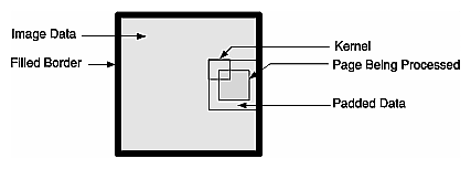
| ilPadSrc | The edge of the input image is padded with the input image's fill value so that a full-sized output image can be processed (see Figure 4-14). See “Fill Value” for more information on an image's fill value. | |
| ilNoPad | No padding is done, and the output image shrinks by the size of the kernel minus one in each dimension. | |
| ilPadDst | Similar to ilNoPad, except that the output, image's border is sufficiently padded with its fill value so that the final image is the same size as the source image. |
The ilConvImg operator performs general image convolution. This class is not an abstract class, so you can use it directly to convolve image data. The constructor for ilConvImg, which is its only public member function, is shown below:
ilConvImg(ilImage* inputImage=NULL,
          ilKernel* inputKernel=NULL, double biasVal = 0.,
          ilEdgeMode eMode=ilPadSrc);
|
This function takes a pointer to the source or input image, a pointer to the kernel, and an enumerated type that matches one of the supported edge modes. The other argument, biasValue, is added to the weighted sum (image data multiplied by kernel weight) for each neighborhood. You can set the bias value with the setBias() function.
You can also perform certain convolutions more efficiently with a separable kernel (one that is specified by row and column vectors). ilSepConvImg, descended from ilSpatialImg, provides this feature. Its constructor accepts the input image, the row and column kernels, the sizes of the kernels, an optional bias value, and an optional edge mode:
ilSepConvImg(ilImage *inputImg = NULL,
       float *xkernel=NULL, float *ykernel=NULL, int xsize=1,
       int ysize=1, double biasVal=0.0,
       ilEdgeMode eMode = ilPadSrc)
       float *zkernel = NULL, int zsize = 1);
|
As shown, the default bias is 0.0, and the default edge mode is ilPadSrc. The default kernel size for each kernel is 5. This operator is especially efficient for kernel sizes 3 x 3, 5 x 5, and 7 x 7.
ilSepConvImg also defines a set of functions to set and get the kernel vectors:
void setXkernel(float *xval); void setYkernel(float *yval); void setZkernel(float *zval, int n = 0); float* getXkernel(); float* getYkernel(); float* getZkernel(); |
setXkernel() allows you to change the row kernel; getXkernel() returns its value. setYkernel() allows you to change the column kernel; getYkernel() returns its value. setZkernel() allows you to change the depth kernel; getZkernel() returns its value. If you replace any kernel with one that has a different size, use ilSpatialImg.setKernelSize() (inherited from ilSpatialImg) to update the sizes.
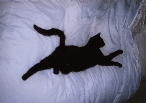
The two blurring operators, ilBlurImg and ilGBlurImg, both blur an image by performing a convolution, but they use different kernels and algorithms for the convolution. ilBlurImg convolves the image with a blurring kernel using the general convolution algorithm defined by ilConvImg. ilGBlurImg (descended from ilSepConvImg) convolves an image with a separable two-dimensional Gaussian kernel. Because ilGBlurImg uses a separable kernel, it is generally more efficient than ilBlurImg. Although different methods are used, often the blurred results do not look significantly different. The reference pages for these classes provide more detailed information on the kernels and convolution algorithms used. Figure 4-15 shows an original image that is used as an example in the following pages.
The ilBlurImg and ilGBlurImg classes have slightly different interfaces:
ilBlurImg(ilImage *img = NULL, float blur=1.,
    float radius=2., ilEdgeMode e=ilPadSrc);
ilGBlurImg(ilImage *inputImg = NULL,
    float blur = 1.0, int xsize = 5, int ysize = 5,
    double biasVal = 0., ilEdgeMode eMode = ilPadSrc);
|
Both constructors take as arguments a pointer to the source image, a blur factor ranging from 0.0 (no blur) to 1.0 (maximum blur), and an enumerated type specifying the edge mode. By default, the blur factor is set to 1.0 and the edge mode is ilPadSrc. The radius argument for ilBlurImg (with a default value of 2.0) and the xsize and ysize arguments for ilGBlurImg (with default values of 5) control the size of the kernel used for blurring. (The ilBlurImg kernel size is equal to 1+radius*2.) ilGBlurImg's biasValue argument, which by default is zero, is added to the final weighted sum.
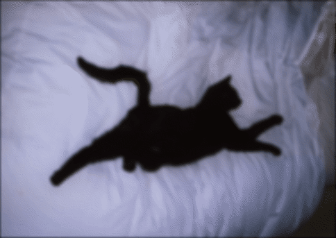
Both classes allow you to dynamically modify the amount of blur by passing a float value to the setBlur() function. You can also change the size of the kernel with setBlurRadius() (for ilBlurImg) or setBlurKernelSize() (for ilGBlurImg). An image blurred with ilBlurImg is shown in Figure 4-16.
The ilSharpenImg class is similar to ilBlurImg, except that instead of using a kernel that blurs, it uses a kernel that sharpens the image data. Its constructor takes a similar set of arguments:
ilSharpenImg(ilImage *img = NULL, float sharpness=.5,
    float radius=1.5,ilEdgeMode e=ilPadSrc);
|
The sharpness factor indicates the degree of sharpening that should occur. This factor can have a value between 0.0 and 1.0, with a default value of 0.5. A sharpened image appears in Figure 4-17.
As with ilBlurImg, you can dynamically change the sharpness factor (with setSharpness()) and the size of the radius (with setSharpenRadius()). getSharpness() and getSharpenRadius() are the query methods that return the values of the sharpness factor and radius. Making the size of the radius too large or repeatedly cycling an image through the sharpening operation can result in a grainy, high-contrast image. Figure 4-18 shows an example of this.
To see additional illustrations of the ilBlurImg and ilGBlurImg transformations, refer to “Spatial Domain Transformations”.
The ilRankFltImg class performs two-dimensional rank filtering, which is typically—though not exclusively—done on black-and-white images. It involves sorting all the pixel values (for each channel) for a neighborhood of pixels. Then, the target pixel is assigned the values corresponding to a specified rank. For example, suppose you have chosen a 3 x 3 neighborhood and a desired rank of 0 (the minimum). In this case, each pixel is assigned the lowest value found among itself and its eight surrounding pixels.
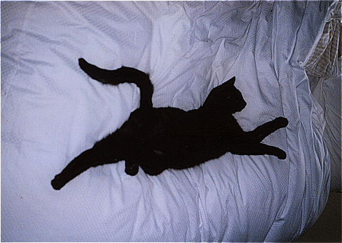
The classes that derive from ilRankFltImg—ilMinFltImg, ilMaxFltImg, and ilMedFltImg—assume that the desired rank is the minimum possible rank, the maximum possible rank, and the median, respectively. Median filtering is useful for removing binary, or impulse, noise in image data. Minimum and maximum rank filtering produce morphological erosion and dilation. An example of an image processed with ilMedFltImg appears in Figure 4-19.
The only public member function defined by these three classes is a constructor, and each of these constructors takes the same set of arguments. ilMinFltImg's constructor is shown below:
ilMinFltImg(ilImage* inputImage = NULL,
    ilEdgeMode edge=ilPadSrc, ilKernel* inputKernel=0);
|
As shown, you need to specify the input image, how pixels at the edge of the image are to be handled, and the kernel. The kernel is treated as a mask. Only nonzero elements are included in the neighborhood; the rest are ignored, as are the kernel weights.
The constructor for the ilRankFltImg superclass takes the same set of arguments and an additional one for specifying the desired rank for the target pixel:
ilRankFltImg(ilImage* inputImage = NULL, int filterRank = -1,
    ilEdgeMode eMode = ilPadSrc, ilKernel* inputKernel=NULL);
|
The default rank of minus 1 indicates that median rank should be used. You can dynamically change the desired rank with the setRank() function. You can also determine what the maximum possible rank is with getMaxRank().
To see additional illustrations of the rank filtering transformations, refer to “Spatial Domain Transformations”.
Morphological operators include shape-dependent, nonlinear image transformations such as erosion and dilation. The operators implemented in IL, ilDilateImg and ilErodeImg, can be used on 1-D, 2-D or 3-D data sets. More powerful morphological operations such as “opening” and “closing” can be performed by chaining together dilation and erosion operations. Opening can be accomplished by an erosion followed by a dilation. Closing can be done with a dilation followed by an erosion.
These operations are defined on binary or grayscale images. Note that you can operate on color images if you remember that “binary” and “grayscale” indicate how the pixel values or intensities in each channel of the image are interpreted. A binary image contains no more than two levels or intensity values: zero and not zero. An 8-bit image with 256 pixel intensities can be treated as a binary image by collapsing the intensities into two groups, for example, a zero pixel intensity could be represented with a zero, and all intensities between 1 and 255 could be represented with a nonzero value. A grayscale image, of course, includes more than two intensity values. Thus, an 8-bit image can be treated as an input image with 256 pixel intensities. Typically, the image has a single channel. (For multichanneled input, the operations are performed on each channel independently.)
Both ilErodeImg and ilDilateImg are derived from ilSpatialImg and thus involve moving a kernel across an image, but the operation performed is not a computed sum. Instead, in morphological operations, the kernel is called a ``structuring element'' (SE) and is represented by an ilKernel. The SE, like the input image, can be interpreted as binary or grayscale. When applied to an image, a morphological operator returns a quantitative measure of the image's geometrical structure in terms of the SE.
The interpretation of the numbers that make up an SE depends on the type of morphological operation being performed. Negative SE elements are always treated as logical “do not cares” when the operation is in progress, image pixels under negative SE elements are ignored. Thus, the support of the SE is limited to those elements that are nonnegative. This permits the creation of odd-shaped SEs. The image pixel under the origin is the one potentially modified.
| Note: You can change the origin of the SE by using ilKernel's setOrigin() method. The default is in the center of the SE. |
The result of erosion or dilation on a binary image (regardless of whether the SE is binary or grayscale) is to turn every pixel either “on” or “off.” A pixel in the output image can then be assigned one of two intensities, corresponding to whether it is on or off. These two intensities are typically the maximum and minimum values of the operator image, which can be set using setMaxValue() and setMinValue() (inherited from ilImage). If they are not explicitly set, the maximum and minimum values are inherited from the input image. For the example of an 8-bit image, the minimum value might be 0 and the maximum 255. A pixel that is 0 in the input image might have a value of 255 in the output image, and a nonzero input pixel might be 0 in the output.
The interpretation of the image or the SE as binary or grayscale can be controlled through the enumerated type ilMorphType, as described below.
If the input image and the SE are binary (ilMorphType = ilBinBin), the SE is used to perform a hit-or-miss transformation. That is, if a zero image pixel falls under a zero SE element, or if a nonzero image pixel falls under a nonzero SE element, the image pixel beneath the SE origin is turned on (assigned the maximum value) for dilation and turned off (assigned the minimum value) for erosion. Typically, for binary images, an SE is composed of negative and positive ones.
If the input image is binary and the SE type is grayscale (ilMorphType = ilBinGray), the nonnegative SE elements determine the support area. In other words, image pixels under negative SE elements are ignored, but if a positive image pixel falls under a non-negative SE element, the target pixel (under the SE origin) is turned on for dilation or off for erosion.
If the input image is grayscale and the SE type is binary (ilMorphType = ilGrayBin), the maximum or minimum (depending on whether dilation or erosion is being performed, respectively) of image pixels falling under positive SE elements is computed.
If the input image and the SE are grayscale and a “set” operation is desired (ilMorphType = ilGrayGraySet), the maximum or minimum (depending on whether dilation or erosion is being performed) of image pixels falling under nonnegative SE elements is computed.
If a “function” operation is desired (ilMorphType = ilGrayGrayFct), the computation is the same as for ilGrayGraySet, except that the SE elements are added to the image pixels before computing the minimum or maximum.
The constructors for erosion and dilation are shown below:
Each operator accepts a pointer to an input image (inputImage), a specification of the type of morphological operation (mtype), a structuring element (the ilKernel pointer se), and an edge mode (eMode).
The morphological transform types, which are members of the enumerated type ilMorphType (defined in il/iflDataTypes.h), are summarized below. These types define whether data in the image and the structuring element (SE) is treated as binary (that is, having a zero or a nonzero value) or as grayscale (that is, with an appropriate range for its data type).
Both ilDilateImg and ilErodeImg define these two functions:
void setMorphType(ilMorphType type); ilMorphType getMorphType(); |
setMorphType() allows you to set the type of morphological operation and getMorphType() returns the type of operation.
The operators described in this section are gradient operators that produce edge-enhanced images by performing orthogonal convolutions with particular kernels. This section focuses on how to use these operators rather than on the specific algorithm implemented by each of these operators. For more information about the algorithms, see the reference pages for the specific class.
The classes described in this section inherit directly or indirectly from ilSpatialImg, as shown in Figure 4-20.
The constructors for the ilRobertsImg and ilSobelImg operators take the same arguments:
ilRobertsImg(ilImage *inputImage= NULL, double biasVal = 0.,
          ilEdgeMode edgeMode = ilPadSrc);
ilSobelImg(ilImage *inputImage = NULL, double biasVal = 0.,
          ilEdgeMode edgeMode = ilPadSrc);
|
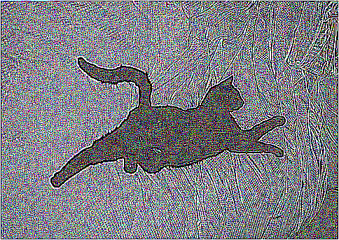
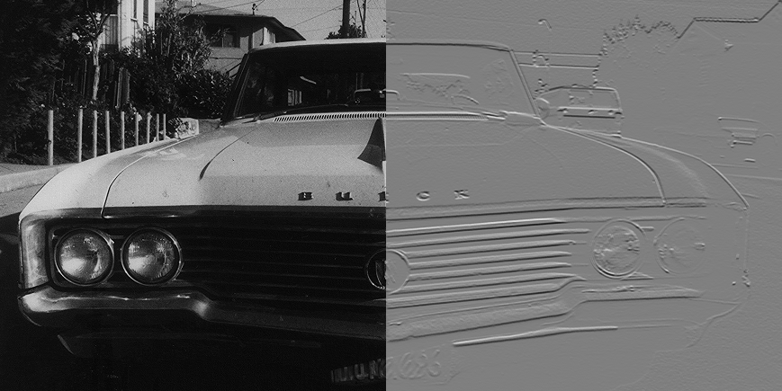
The image to be transformed is specified by inImg. The other two arguments, which have default values, indicate a bias value to be added as each pixelwise convolution is performed and how pixels at the edge of a page are to be handled. These arguments have the same meaning as the ones supplied in the ilConvImg constructor, which is described in the preceding section. As explained in more detail in the reference pages, these operators perform two orthogonal, two-dimensional convolutions, which are then combined with predefined kernels. The resulting images are edge-enhanced images. An example image produced by ilRobertsImg is shown in Figure 4-21.
The constructor for the ilLaplaceImg operator uses the same arguments as the constructors shown above, plus an additional argument that allows you to select one of two predefined kernels:
ilLaplaceImg(ilImage *inputImage= NULL, double biasVal = 0.,
          ilEdgeMode eMode = ilPadSrc, int kerno = 1);
|
The kerno argument can be either 1 or 2; the corresponding kernels are listed in the reference page for ilLaplaceImg. You can use setKernel() to specify either kernel after you have created an ilLaplaceImg object.
A compass operator measures gradients in a specified direction. The ilCompassImg operator allows you to specify the desired direction as an angle between 0 and 360 degrees or as one of eight compass points. You can also specify the size of the kernel to be used. Once all this information is supplied, a square kernel is generated, which is then convolved with the image data. Here's the class constructor:
ilCompassImg(ilImage *inImg= NULL, float angleDir = ilCompassN, double biasVal = 0., int kernSize = 3,ilEdgeMode edgeMode = ilPadSrc); |
The angleDir argument can be a number or one of the following values (see Table 4-2), which correspond to the compass points.
Table 4-2. Compass Directions for the ilCompassImg Operator
Value | Angle (in degrees |
|---|---|
ilCompassN | 0 |
ilCompassNE | 45 |
ilCompassE | 90 |
ilCompassSE | 135 |
ilCompassS | 180 |
ilCompassSW | 225 |
ilCompassW | 270 |
ilCompassNW | 315 |
North, or 0 degrees, is the top of an image (as it is displayed using ilDisplay). Angles are measured from north in a clockwise direction. The bias value and edge mode arguments for the constructor have the same meaning as those for ilLaplaceImg. Since the kernel is always square, only one dimension of its size needs to be specified. You can set and retrieve the bias value with setBias() and getBias(), which are defined by ilOpImg.
Figure 4-22 shows an example image produced by using ilCompassImg.
Once you have created an ilCompassImg operator, you can dynamically change the direction of the gradient with either setAngle() or setXYWt():
void setAngle(float angleDir = ilCompassN); void setXYWt(float Xwt = 0.0, float Ywt = 1.); |
The setXYWt() function specifies weights in the x and y dimensions, which are then used to generate the kernel. The ilCompassImg reference page describes in more detail how the kernel is generated from the angle or weights.
You can query an ilCompassImg about its angle or weights with these functions:
float getAngle(); void getXYWt(float& Xwt, float& Ywt); |
it is often convenient to manipulate data in the frequency domain, particularly when restoring, enhancing, or removing noise from images. The ilRFFTfImg operator described in this section performs a forward fast Fourier transform (FFT) on an image (containing “real-valued” data, not complex). Once you have converted an image into the frequency domain, you can use any of the numerous Fourier operators to manipulate the image data. Then, when you are finished, you can use ilRFFTiImg, which performs an inverse FFT, to convert back to the spatial domain. Figure 4-23 shows the frequency domain operators and how they fit into IL inheritance hierarchy.
As shown in Figure 4-23, both ilRFFTfImg and ilRFFTiImg inherit publicly from ilOpImg and privately from ilFFTOp. You should think of these two classes as operators that simply use the forward and inverse transform functions defined by ilOpImg. ilRFFTiImg tries to set the page size large enough to hold an entire channel of the image.
The FFTs are performed using the Prime Factor algorithm, using floating point arithmetic. (For more information on the specifics of this algorithm, see the ilFFTOp reference page and the article “Symmetric FFTs,” by Paul N. Swarztrauber, Mathematics of Computation, Vol. 47, Number 175, July 1986, pp. 323-346.) The only restriction this algorithm places on the input image is that it have a real (non-complex) data type other than iflBit. However, the algorithm is most efficient if the image already contains floating point data (so it does not have to be converted for processing and then converted back again), has an iflSeparate order, and has dimensions that are products of small primes. Dimensions that are a power of two yield the most efficient computation. The reference pages for each of the Fourier operators described in this section contain more information about the methods used to perform the computations as well as hints about how to achieve the greatest possible efficiency.
The constructor for the ilRFFTfImg operator and the member function, ilFFTOp.ilRfft(), perform a forward FFT.
ilRFFTfImg(ilImage *img = NULL, short option = ilFFTxform2D);
ilStatus ilRfftf(ilImage* src, int srcCh, void* dst,
    short opt = ilFFTxform2D, ilMpCacheRequest* req = NULL);
|
Using the ilRFFTfImg operator to perform a forward FFT is relatively easy. The first argument is a pointer to the source image that is to be transformed. The second argument, called option, allows you to choose whether a one- or two-dimensional transform is performed; if it is:
1, a one-dimensional FFT is performed on the rows of data
2, a one-dimensional FFT is performed on the columns of data
3, a two-dimensional FFT is performed (the default)
You can dynamically change this parameter with the setOption() function.The first four arguments to ilRFFTfImg() function specify which channel of the source image is to be transformed and into which channel of the destination image the result should be put. In this example, channel 0 of srcImg is transformed and placed into channel 0 of destImg. The size of both of these images must be the same. The last argument for this function specifies which of the three options described above is desired. (It has the same meaning as the second argument to the ilRFFTfImg constructor.)
Since the source image must contain real data (not complex numbers), the output is conjugate-symmetric. In other words, only two of the four quadrants are unique, and only these are computed for the output. The output is complex, however, so both the real and imaginary results must be reported. Because of this, the destination image has the same x and y dimensions as the source image. Table 4-3 shows the format of the output from the ilRFFTfImg operator function. (The origin is in the upper left corner.)
Table 4-3. Output of a Forward Fourier Transform (if nx and ny are even)
| 0 | 1 | 2 | 3 | 4 | ... | nx-3 | nx-2 | nx-1 |
|---|---|---|---|---|---|---|---|---|---|
0 | real | real | imag | real | imag | ... | real | imag | real |
1 | real | real | imag | real | imag | ... | real | imag | real |
2 | imag | real | imag | real | imag | ... | real | imag | imag |
3 | real | real | imag | real | imag | ... | real | imag | real |
4 | imag | real | imag | real | imag | ... | real | imag | imag |
... | ... | ... | ... | ... | ... | ... | ... | ... | ... |
ny-3 | real | real | imag | real | imag | ... | real | imag | real |
ny-2 | imag | real | imag | real | imag | ... | real | imag | imag |
ny-1 | real | real | imag | real | imag | ... | real | imag | real |
Columns 1 through nx-2 contain the real and imaginary components of a complex transform, for example, column 1 contains the real component and column 2 the corresponding imaginary component of the first complex FFT output. The column 0 represents the 0-frequency (or DC) component, and column nx-1 represents the highest (Nyquist) frequency along the x-direction. These two columns resemble the output of a real-valued FFT. In the example shown, both nx and ny are assumed to be even. If nx were odd, the Nyquist column would be missing. If ny were odd, the last row shown would be missing. Table 4-4 shows the output format if both nx and ny are odd.
Table 4-4. Output of a Forward Fourier Transform (if nx and ny are odd)
| 0 | 1 | 2 | 3 | 4 | ... | nx-2 | nx-1 |
|---|---|---|---|---|---|---|---|---|
0 | real | real | imag | real | imag | ... | real | imag |
1 | real | real | imag | real | imag | ... | real | imag |
2 | imag | real | imag | real | imag | ... | real | imag |
3 | real | real | imag | real | imag | ... | real | imag |
4 | imag | real | imag | real | imag | ... | real | imag |
... | ... | ... | ... | ... | ... | ... | ... | ... |
ny-2 | real | real | imag | real | imag | ... | real | imag |
ny-1 | imag | real | imag | real | imag | ... | real | imag |
This format is what is expected as input by all the Fourier operators described in this section. In particular, the constructor for the ilRFFTiImg operator expects this format in their source image. They perform an inverse FFT, which is to say they convert the input Fourier data back to the spatial domain:
ilRFFTfImg(ilImage *img = NULL, short option = ilFFTxform2D);
ilStatus ilRfftf(ilImage* src, int srcCh, void* dst,
    short opt = ilFFTxform2D, ilMpCacheRequest* req = NULL);
|
The ilRFFTiImg constructor takes a pointer to the source image and the same option argument described above. (The ilRFFTiImg operator also defines the same setOption() function described above.) For the ilRFFTiImg() function, the source and destination images (src and dst) must be the same size; the srcCh and dstCh arguments specify the channel to be transformed and the destination channel number. Both the constructor and the function produce output data that is real. The output of the forward transform is multiplied by 1.0/(nx*ny) so that the forward transform followed by the inverse returns the original image unscaled.
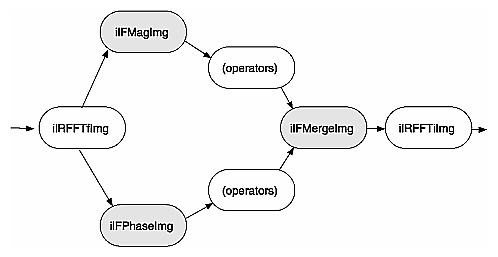
The operators described in this section allow you to separate the magnitude and phase components of a complex Fourier image so that you can process or filter them independently and then combine them into a complete image when you are finished. Such an operator chain would look like Figure 4-24.
As you might expect from their names, the ilFMagImg operator computes the magnitude of an input complex Fourier image, and ilFPhaseImg determines the phase component. The constructors for both of these operators expect the format produced by ilRFFTfImg (which is described above):
ilFMagImg(ilImage *img = NULL); ilFPhaseImg(ilImage *img = NULL); |
The x -dimension of the output image for both these operators is half of the input image's size, plus one; the y dimension is unchanged. The x dimension shrinks because the input image uses two columns for each Fourier element, one for the real component and one for the imaginary, whereas the magnitude and phase are not complex. For a complex number represented by a + ib,
the magnitude is
and the phase is
atan (b/a)
An operator that is similar to ilFMagImg, ilFSpectImg, computes the spectrum of a Fourier image. The computation is the same as that performed by ilFMagImg, but all quadrants are represented in the output image, not just the two that are unique. As a result, the size of the output image is the same as that of the input image, and the origin of the output image is at its center rather than its upper left corner. You might use an ilFSpectImg object for displaying, although you probably want to scale the spectral values using ilHistScaleImg. (This operator is described in “Radiometric Transformations”.) An ilFMagImg object is more efficient for processing since redundant calculations are not performed.
The constructor for ilFSpectImg simply takes a pointer to the source image:
ilFSpectImg(ilImage *img= NULL); |
The ilFMergeImg operator merges an ilFMagImg and an ilFPhaseImg to produce the original whole Fourier image. The merged image is converted from polar to rectangular form so that it is in the format expected by ilRFFTiImg. The constructor for ilFMergeImg takes pointers to the two images and an int that specifies the desired x dimension of the final image:
ilFMergeImg(ilImage *mag, ilImage *ph, int xsize); |
The xsize argument is required because the x dimension of a merged image can't be uniquely determined from the x dimension of mag or phase. For example, if mag and phase have x dimensions of 129, the merged image could have an x dimension of either 256 or 257. You can explicitly set the x dimension with setXsize().
Two filter operators are provided for use on Fourier images: ilFExpFiltImg and ilFGaussFiltImg. These operators derive from ilFFiltImg, an abstract class that implements the basic support for frequency domain filtering. (You can derive your own filter as described in “Deriving From ilFFiltImg”.) Both ilFExpFiltImg and ilFGaussFiltImg expect input in the format produced by ilRFFTfImg. Typically, you'll apply the ilRFFTiImg operator to the filtered image in order to view the results in the spatial domain.
The constructors for these operators are shown below:
ilFExpFiltImg(ilImage *img, float alpha, float beta,
    float gamma,float eccent, float theta);
ilFGaussFiltImg(ilImage *img, float hfgain, float dcgain,
    float minhalf, float majhalf, float theta);
|
For more information about what these arguments mean, see the filter equations below and the reference pages for these two operators.
This is the filtering equation used by ilFExpFiltImg:
 |
This is the filtering equation used by ilFGaussFiltImg:
 |
where for both equations:
H() = transfer function of the filter
u,v = two-dimensional frequency coordinates
 |
xSize = x dimension of the source image
ySize = y dimension of the source image
and where for ilFExpFiltImg:
 |
the filter and where for ilFGaussFiltImg:
hf = gain of filter at the Nyquist (highest) frequency
dc = gain of filter at zero frequency
 |
minHalf = frequency of half-power point along the minor elliptical axis
majHalf = frequency of half-power point along the major elliptical axis
Table 4-5 shows two examples of specific values that might be passed in for ilFGaussFiltImg.
Table 4-5. Sample Parameter Values for ilFGaussFiltImg
Parameter | High-pass | Low-pass | |
|---|---|---|---|
dc | 0.004 | 1.0 | |
hf | 3.0 | 0.002 | |
minHalf | 0.01 | 0.05 | |
majHalf | 0.01 | 0.05 | |
0.0 | 0.0
|
The high-pass values create a two-dimensional circular high-pass filter with a cutoff value of 0.01 on both axes; its DC gain is 0.004, and its gain at the highest frequency is 3.0. A high-pass filter diminishes the constant or slowly-changing portions of an image and thereby accentuates the edge portions (creating a high-contrast, edge image). The low-pass values create a two-dimensional circular low-pass filter with a cutoff value of 0.05 on both axes; its DC gain is 1.0, and its gain at the highest frequency is 0.002. A low-pass filter diminishes the dramatically changing values at edges in an image and thereby accentuates the constant or slowly varying portions (creating a blurry image). See Figure 4-25 and Figure 4-26.
Functions are defined in ilFExpFiltImg.h and ilFGaussFiltImg.h to set the value of all the parameters used in the constructors for both operators.
In ilFExpFiltImg.h:
void setAlpha(float val); void setBeta(float val); void setGamma(float val); void setEccent(float val); void setTheta(float val); |
In ilFGaussFiltImg.h:
void setHFgain(float val); void setDCgain(float val); void setMinHalf(float val); void setMajHalf(float val); void setTheta(float val); |
See the reference pages for more information about these functions.
The two operators described in this section are ilFConjImg and ilFRaisePwrImg, both of which derive from ilFMonadicImg. (See “Deriving From ilFMonadicImg or ilFDyadicImg” for more information about deriving your own operator from this class.) ilFConjImg and ilFRaisePwrImg expect a source image in the format produced by ilRFFTfImg. Typically, you'll need to convert ilFRaisePwrImg's output to the spatial domain by using ilRFFTiImg. (You do not typically need to convert the result of applying ilFConjImg to an image back to the spatial domain; usually, it is used in the middle of a chain of operators in the frequency domain.)
As its name suggests, ilFConjImg computes the complex conjugate of an image; it also multiplies the complex values by a real factor:
ilFConjImg(ilImage *img=NULL, float scale = 1.0); |
The scale argument is used to multiply or scale the values; the default value of 1.0 results in no scaling. You can change the scaling factor with setScale(). ilFConjImg is useful in computing the magnitude squared of the Fourier transform. For example, assume theImg is a pointer to a valid ilImage in the spatial domain:
ilRFFTfImg forwardImg(theImg); ilFConjImg conjugateImg(&forwardImg); ilFMultImg magSquaredImg(&forwardImg, &conjugateImg); |
You can then display magSquaredImg.
The ilFRaisePwrImg operator raises the natural log of the magnitude values of a Fourier image by a power, exponentiates the result, and writes the values back in complex rectangular form:
This root-filtering operation is useful for image sharpening. The constructor for this class is shown below:
ilFRaisePwrImg(ilImage* src, float power); |
The log of the magnitude values of the source image, src, are raised by power, exponentiated, and converted back to complex rectangular form. The valid range for power is 0.0-1.0. You can set this value dynamically with setPower().
Three operators take two Fourier images as inputs:
These classes derive from ilFDyadicImg, which implements the basic support for dual-input Fourier operators, and they expect input images in the format produced by ilRFFTfImg. To convert the processed data back to the spatial domain, you need to apply the inverse transform implemented by ilRFFTiImg. See “Deriving From ilMonadicImg or ilPolyadicImg” for more information about deriving your own dual-input Fourier operator.
The constructors for ilFCrCorrImg, ilFMultImg, and ilFDivImg expect two images, which must be the same size:
ilFCrCorrImg(ilImage *img1 = NULL, ilImage *img2 = NULL);
ilFMultImg(ilImage *img1 = NULL, ilImage *img2 = NULL);
ilFDivImg(ilImage *img1 = NULL, ilImage *img2 = NULL,
    int ckDiv = 1);
|
To compute the cross-correlation, ilFCrCorrImg multiplies src1 by the conjugate of src2 and then normalizes the result using the DC (or (0,0)) coefficient of src1. One of the principal applications of cross-correlation in image processing is in prototype matching, where one tries to match a given unknown image to a known image. The closest match can be found by selecting the image that yields the correlation function with the largest value.
Multiplying two Fourier images is equivalent to convolving them in the spatial domain. Since the Fourier algorithm is very efficient, you might want to choose ilFMultImg over one of ilConvImg's subclasses if you are using a large kernel for the convolution.
ilFDivImg divides src1 by src2 and, by default, checks for division by zero according to the following rules:
If the numerator of the real or imaginary part is positive and the denominator is zero, the result is the largest possible floating point value (3.40282346e+38).
If the numerator of the real or imaginary part is negative and the denominator is zero, the result is the smallest possible floating point value (-3.40282346e+38).
If both the numerator and the denominator are zero, the result is zero.
You can call setCheck() and pass in a 0 to prevent ilFDivImg from checking for division by zero.
You can use ilFDivImg in image restoration. Given the Fourier transform of a degraded or noisy image and the Fourier transform of the noise function (or “noise image”), you can retrieve a clean image by dividing (in the frequency domain) the degraded image by the noise image. Once converted back to the spatial domain, you can then display the clean image.
it is often desirable to collect statistical information about an image, such as how frequently various pixel values occur and what the minimum and maximum pixel values are. The ilImgStat class computes this kind of information for an entire image or for a specified region within an image. More specifically, for each channel of image data, it computes:
The ilImgStat class inherits from ilLink, as shown in Figure 4-27.
ilImgStat does not derive from ilImage, so its constructor does not create an ilImage. It derives from ilLink. Thus, an ilImgStat object cannot be passed as an image to another operator, but it might be one of an operator's input arguments.
Multiprocessing on an ilImgStat object can turned on or off and queried using the enableMP() and isMPenabled() functions.
ilImgStat has two parents: the input image from which the data is derived, and the ROI, if any. If either of these objects is altered, the two ilLink inheritance mechanism ensures that the ilImgStat object reconfigures itself.
Calculation of the statistics is deferred until it is triggered by one of the get...() methods. If only the minimum-maximum is requested, a histogram is not computed. For any other get...() method, the histogram is computed. If the data order is separate, on the minimal subset of the channels is analyzed. The analysis results (minimum, maximum, historicity, mean, standard deviation, are cached in the ilImgStat to avoid recalculation. If the object is altered either directly or indirectly with inheritance, the cached data id discarded.
| Note: There is an “auto calc” flag that modifies this default behavior. For more information, see the ilImgStat man page. |
The constructor for the ilImgStat class allows you to specify whether the data should be computed for the entire source image or for just a portion of it, as shown in the next code fragment. The portion is defined as a region of interest (ROI); see “Defining a Region of Interest” for more information about the ilRoi class, which defines an ROI within an image.
ilImgStat(ilImage* img=NULL, ilRoi* roi=NULL,
    int xoffset=0, int yoffset=0, int zoffset=-1, nz=0);
|
The xoffset, yoffset, and zoffset parameters represent the offsets into the input image, img, at which the ROI is placed. The z argument specifies the starting z value, and nz indicates the size of the z tile. Thus, you can use these values to effectively create a 3-D ROI. The coordinates of the roi image are specified in the coordinate space of the input image.
You can also specify an ilRoi and its offsets for the ilImgStat with the following setRoi() functions:
ilImgStat::setROI(ilRoi* roi, int xoffset=0, int yoffset=0); ilImgStat::setZ(int z, int nz=1); |
If no ROI is specified, ilImgStat performs its computations over the whole image.
ilImgStat::clearZ() unsets the tile in the Z dimension.
An image's histogram, which is computed for each channel of image data, is defined by:
the starting and ending pixel values—these establish the endpoints of the histogram's range.
the number of bins—the range is evenly divided into a specified number of bins.
the size of each bin—the size is the range covered by each bin; this is computed by dividing the total range by the number of bins.
You use the following methods to determine the number of bins, the bin size, and the lower limit of the first bin for any particular channel:
double lowerLimit = myImgStat.getStart(1); double upperLimit = myImgStat.getEnd(1); double binSize = myImgStat.getBinSize(1); int binCount = myImgStat.getBinCount(1) |
The argument for these functions is an int that specifies the desired channel.
Once you have created an ilImgStat object, you can specify the limits of a histogram using the following methods:
void setInput(ilImage* in) void setLimits(double start, double end); void setBinCount(int count); |
where in is the image associated with the histogram, start and end specify the lower and upper endpoints of the range of pixel values, and count is the number of bins in which pixel values are collected. The maximum number of bins allowed is 4096.
To access the histogram of the source image's pixel values, use the getHist() function:
unsigned long* getHist(int chan=0); |
where chan is the color channel.
The getHist() function returns a pointer to an array that is allocated by ilImgStat. The values in the array correspond to the number of pixels that have values within each bin's respective range. To represent a probability distribution, copy the long array into a float array, and then divide each element of the array by the total number of pixels used to compute the histogram for that particular channel. You can obtain the number of pixels used with getTotal():
long totalPixelCount = myImgStat.getTotal(1); |
The argument for this function is an int that specifies the desired channel. (The number of pixels used for each of the channels might vary if you have specified different endpoints for the different channels.)
If the image's pixel ordering is iflSeparate, you can make multiple calls to getHist() for each channel and specify varying numbers of bins and starting points and endpoints. However, the histograms for all channels of iflInterleaved or iflSequential images are computed on the first call to getHist(), so the number of bins and the starting points and endpoints are fixed for subsequent calls. If you need to change the histogram's attributes for subsequent calls, use reset(). This function deallocates the array created with getHist() and enables you to start over. (In general, you should call reset() or the ilImgStat destructor as soon as you are finished with a histogram to minimize memory usage.) If you need a histogram you have already computed, copy it into your own buffer before calling reset().
The ilImgStat class defines functions that return the minimum value, maximum value, mean, and standard deviation of a particular channel:
double getMin(int c=0); double getMax(int c=0); double getMean(int c=0); double getStdDev(int c=0); |
These functions all return the desired number as a double, regardless of the data type of the image.
Two other support functions are provided:
void setHwEnable(ilHwAccelEnable enable); ilHwAccelEnable getHwEnable(); void qCalcStats(ilMpNode* parent, ilMpManager** pMgr=NULL); |
You can use the first function shown above to enable and disable hardware acceleration by passing in TRUE or FALSE, respectively. You can use getHwEnable() to determine whether or not acceleration is enabled.
The last function allows your application to calculate a histogram asynchronously.
This section describes a set of operators that adjust all the pixels of an image so that together they have certain specified characteristics. Three of the operators described in this section—ilHistNormImg, ilHistEqImg, and ilHistScaleImg—modify an image's pixel values channel by channel, so that the image's histogram has certain desired properties. You can limit the area for which statistics are computed by specifying an ROI and its offsets when you create these operators; the operators then adjust all the pixels of the image so that the entire image's histogram matches that computed for the ROI. (See “Defining a Region of Interest” for more information about ROIs.) If you have already created an image's histogram using ilImgStat as described in the previous section, you can pass a pointer to the existing ilImgStat object to speed the transformations performed by these operators.
The following radiometric operators are described in this section:
ilScaleImg | linearly scales the pixel data of an image so that it falls in a new specified range |
ilHistNormImg | transforms an image so that its histogram is normalized (Gaussian) and so that it has a specified mean and standard deviation |
ilHistEqImg | transforms an image so that its pixel values are uniformly distributed (so that the cumulative histogram is linear) |
ilHistScaleImg | clamps values to a specified percentage distribution of the high- and low-intensity pixels and scales the remaining data between the clamp values |
ilThreshImg | sets each pixel to the image's minimum or maximum value, depending on whether the pixel is less than or greater than a specified threshold value |
ilLutImg | transforms a source image using a specified lookup table |
ilPiecewiseImg | transforms a source image using a lookup table created with a piecewise linear mapping function |
The operators that perform radiometric scaling, ilScaleImg and ilHistScaleImg, are accelerated on certain hardware platforms. The ilLutImg operator and the operators derived from it, such as ilPiecewiseImg, ilHistNormImg and ilHistEqImg, are also accelerated provided they meet the constraints specified in “Using Hardware Acceleration”. The ilThreshImg operator is also accelerated through the LUT mechanism, even though it is not derived from ilLutImg. All these classes derive directly or indirectly from ilMonadicImg, as shown in Figure 4-28.
The ilScaleImg operator linearly scales the pixel data of an image so that it falls in a specified range. If you do not know the range of the input pixels, the first constructor shown below must be used. This constructor uses the minimum and maximum value fields of the input image to determine the input range, and it assumes an output range of 0 to 255. If you want to override the range of the input pixel data, you can use the second constructor and also specify an output range. The default is 0 to 255.
ilScaleImg(ilImage* img = NULL); ilScaleImg(ilImage* img, double inMin, double inMax, double outMin=0, double outMax=255.999); |
Pixels of value inMin are scaled to outMin, while those of value inMax are scaled to outMax. Pixels channel values lying between these extremes are scaled accordingly. Pixels outside the input domain are clamped between outMin and outMax.
The scaling function is normally computed based on inMin and inMax (the domain) and outMin and outMax (the range). To do this scaling, ilScaleImg computes the slope and intercept of a linear function of the form:
Thus, an input pixel of value x becomes an output pixel of value f(x). The slope and intercept are computed as follows:
 |
You can alter the operator's parameters with these member functions:
void setRange(double outMin, double outMax); void setDomain(double inMin, double inMax); |
You can control the scaling behavior with these functions:
void resetDomain(); void resetRange(); void resetScaling(); void setScaling(double slope, double intercept); |
resetDomain() invalidates the current input levels and, if none are specified using setDomain(), the minimum and maximum values of the input images are used for the domain.
resetRange() invalidates the current output levels and, if none are specified using setRange(), default values are computed using the input domain and the scaling values (slope and intercept). An example image produced using ilScaleImg is shown in Figure 4-29.
resetScaling() forces the operator to forget any values explicitly set for slope and intercept and to compute them as shown above.
setScaling() allows you to explicitly set the values of the slope and intercept of the scaling function.
Both ilHistNormImg and ilHistEqImg derive from ilHistLutImg, which itself derives from ilArithLutImg. This inheritance allows the histogram operators to use lookup tables to determine resulting values, rather than perform the computations on a per-pixel basis. As a result, the histogram operators are more efficient.
The constructors for ilHistNormImg are:
ilHistNormImg(ilImage *img, iflPixel &mn, iflPixel &std,
    ilImgStat *imgstat = NULL, ilRoi *Roi = NULL,
    int xoffset = 0, int yoffset = 0, int zoffset = 0);
ilHistNormImg(ilImage *img=NULL, ilImgStat *imgstat=NULL,
    ilRoi *Roi=NULL, int xoffset=0, int yoffset=0,
    int zoffset=0);
|
The first constructor allows you to specify the source image and the desired mean, mn. and standard deviation, std. The second constructor takes a source image and computes default values for the mean and standard deviation. The mean for each channel is computed as the average of the minimum and maximum values of the source image for that channel. The standard deviation is set to 1.0 for each channel.
The iflPixels can use any data type, but their number of channels must match that of the source image. If you have already created an ilImgStat object (for the source or even a different image), you can pass a pointer to it. This makes ilHistNormImg more efficient. If you supply both an ilImgStat and an ilRoi, the histogram computed for the ilImgStat is used and the ilRoi is ignored.
You can dynamically change the mean, the standard deviation, the ilImgStat object, and the ilRoi and its offsets with the following ilHistNormImg.h functions:
void setMean(iflPixel& mean); void setStdev(iflPixel& stdev); void setImgStat(ilImgStat* imgstat); void setRoi(ilRoi* Roi, int xoffset = 0, int yoffset = 0); |
The setImgStat() and setRoi() functions are inherited from ilHistLutImg.
Histogram equalization and histogram scaling of an image are often performed to enhance the contrast of an image. Histogram equalization results in an image with pixel values that are more evenly distributed.
The constructor for ilHistEqImg is shown below:
ilHistEqImg(ilImage *img = NULL, ilImgStat *imgstat = NULL,
    ilRoi *Roi = NULL, int xoffset=0, int yoffset=0,
    int zoffset=0);
|
As shown, you specify the source image, the ilImgStat object if one exists, and an optional ROI along with its offsets. This class also inherits setImgStat() and setRoi() functions as does ilHistNormImg.
The constructor for ilHistScaleImg is more complicated:
ilHistScaleImg(ilImage* img = NULL, double lowClip=0,
    double highClip=0, double outMin=0, double outMax=255,
    ilImgStat* imgstat=NULL, ilRoi* Roi=NULL,
    int xoffset = 0, int yoffset = 0);
|
The src argument specifies the source image. The next four arguments specify how the source image should be transformed. The highClip and lowClip arguments indicate what percentage of the high and low intensity pixels should be clamped to the values specified by outMax and outMin, respectively. Imagine that the pixels are sorted in order of increasing intensity, as in a histogram. Then, highClip percent of the highest-intensity pixels are set to the outMax value, and lowClip percent of the lowest-intensity pixels are set to the outMin value. After the desired pixels have been clipped, the remaining pixels are scaled linearly between the clamp values. The optional ilImgStat and ilRoi objects (and offsets) each have the same meaning as with ilHistNormImg.
You can dynamically change all these arguments with the following ilHistScaleImg functions:
void setImgStat(ilImgStat* imgstat); void setRoi(ilRoi* Roi, int xoffset = 0, int yoffset = 0); void setClip(double lowClip, double highClip); void setRange(double outMin, double outMax); |
One other useful function, setHistLimits(), allows you to change the limits between which the histogram is to be computed:
void setHistLimits(double low, double high); |
The two arguments, low and high, define the histogram's limits.
Be careful when changing the input to any of the histogram operators by using setInput(). (See “Dynamically Reconfiguring a Chain” for more information.) If an ilImgStat has already been specified in a histogram operator constructor and then setInput() is called, the old ilImgStat is used unless you call setImgStat() with a new one. You can use NULL in setImgStat() to force a new one to be computed.
The ilThreshImg operator sets each pixel (on a channel by channel basis) to the image's minimum or maximum allowable value, depending on whether the pixel is less than or greater than a specified threshold value. (See “Minimum and Maximum Pixel Values” for more information about how to set an image's minimum and maximum pixel values.)
To create an ilThreshImg operator, you can use one of the following constructors:
ilThreshImg(ilImage* img, const iflPixel& thresh); ilThreshImg(ilImage* img= NULL, float val = 0); |
In the first constructor, the threshold is specified as an iflPixel, and a different threshold level can be applied to each channel of the source image. In the second constructor, the same threshold, val, is applied to all channels.
Each channel or each pixel of the source image is compared to the threshold value, thresh or val. If the channel value is less than the threshold value, it is set to the image's minimum channel value. If the channel value is greater than or equal to the threshold value, it is set to the maximum channel value. (If thresh is a single-channel pixel, its value is used for all channels of the source image.)
You can query an image about its threshold value and dynamically change this value with these functions:
void getThresh(iflPixel& thresh); void setThresh(float val); void setThresh(const iflPixel& thresh); |
getThresh() returns the threshold value by reference, and setThresh() sets the threshold value.
The ilLutImg class transforms a source image using a specified lookup table (LUT). As mentioned previously, ilArithLutImg (see “Single-input Operators”) and ilHistLutImg (see “Histogram Operators”) derive from ilLutImg. Normally, the LUT and the image have the same number of channels. However, two other possibilities are allowed: if the LUT has only one channel, it is applied to each channel of the image. If the source image has only one channel while the LUT has n channels, each LUT channel is applied to the source image in turn, producing an ilLutImg with n channels. (For any other combination, the ilStatus value ilLUTSIZEMISMATCH is returned by any data access operations.)
The first constructor below allows you to specify the source image and the LUT. The second one lets you specify the source image and sets the LUT to NULL. You can later specify a LUT using the setLookUpTable() function.
ilLutImg(ilImage* src, const iflLut& table); ilLutImg(ilImage* src = NULL); |
See “Using iflLut” for more information about the iflLut class and also for an explanation of how lookup tables can be stored and retrieved using SGI image files.
You can dynamically change or retrieve the LUT with these functions:
ilStatus setLookUpTable(const iflLut& table); |
If you change the LUT, the output number of channels and data type are updated, if necessary, to accommodate the new LUT.
The ilPiecewiseImg class, derived from ilLutImg, simplifies the task of constructing a lookup table when only a piecewise linear mapping is needed from the input pixels to the output data. The constructor accepts the source image, a list of breakpoints, and the length of that list:
ilPiecewiseImg(ilImage* inputImage = NULL,
    const iflXYSfloat* bkpts=NULL, int length=0);
|
A breakpoint is a point on a piecewise continuous function where two continuous segments meet, as shown in Figure 4-30.
The endpoints, 0 and 255, are made breakpoints by default (this does not affect the length of the breakpoints list). If a breakpoint is entered outside the range, it is clamped to the appropriate endpoint.
Several functions are provided to manipulate the breakpoints:
ilStatus setBreakpoints(const iflXYSfloat* bkpts=NULL,
          int length=0, int chan=-1);
ilStatus insertPoint(const iflXYSfloat& point, int index,
int chan=-1);
ilStatus replacePoint(const iflXYSfloat& point, int index,
int chan=-1);
ilStatus removePoint(int index, int chan=-1);
|
allows you to specify a new list of breakpoints (of length). You can specify a list for a specific channel with the chan argument; if this is minus 1 (the default), the list is used for all channels in the image. | |
inserts a breakpoint point after the one at index in the list for channel chan. | |
replaces the breakpoint at index in the breakpoint list for channel chan with point. | |
removes the breakpoint at index; you specify which channel's breakpoint list with chan. |
You can query an ilPiecewiseImg about its breakpoints with these functions:
int getBreakpoints(iflXYSfloat* bkpts, int chan=0);
int getNumBreakpoints(int chan=0);
void getPoint(iflXYSfloat& point, int index, int chan=0);
float findPoint(iflXYSfloat& loc, int& index,
    int forInsert=0, int chan=0);
|
accepts a pointer to a list of breakpoints and returns the length of the breakpoint list for chan as an int and the breakpoint list itself through bkpts (you must allocate enough space in bkpts before this function call). | |
returns the number of breakpoints in the breakpoint list for chan. | |
returns the breakpoint at index in the breakpoint list for chan by reference in point. | |
accepts a location (loc), an index into the breakpoints list for chan, and a flag specifying whether the closest breakpoint should be found (forInsert = 0) or whether the closest edge should be found (forInsert = 1). In either case, the distance between the given location and the found location is returned as a float, the breakpoint is returned by reference in loc, and the index of that breakpoint is returned in index. |
In all of the above functions, chan is 0 by default, specifying the first channel of the image.
Figure 4-31 shows an example of an application with a graphical user interface (imgview) that can be written with ilPiecewiseImg.
The three operators described in this section—ilBlendImg, ilMergeImg, and ilCombineImg—combine two or more images into one using different methods:
ilBlendImg blends two images using a specified alpha value or alpha images that indicate how to weight the images relative to each other.
ilMergeImg merges a series of images into a single multiple-channel image.
ilCombineImg combines two images using a mask to define which portions of the two images to use in the final combined image.
These three classes have very different pedigrees, as shown in Figure 4-32.
The constructors for ilBlendImg allow you to specify a constant alpha value or to specify third and fourth images that contain alpha values for each pixel of the foreground and background images. You can also select the way in which the foreground and background images are blended:
ilBlendImg(ilImage* fore, ilImage* bkgd, float alpha);
ilBlendImg(ilImage* fore = NULL, ilImage* bkgd = NULL,
          ilImage* alphaf = NULL, ilImage* alphab=NULL,
          ilCompose comp=ilAplusB);
|
The first constructor specifies one constant alpha value (which should fall between 0.0 and 1.0) that is used to calculate a foreground and background alpha. If the second constructor is used, the alpha values are taken from the first channel of alphaf (for the foreground alphas) and alphab (for the background alphas). The other channels, if any, are ignored. In the default mode (ilAplusB), if alphab is NULL, then the background alpha values for each pixel are computed from alphaf as 1 - alphaf. Figure 4-33 shows an example image produced using the ilBlendImg operator and the ilAplusB compose mode.
The second constructor also allows you to specify the composition mode. See Figure 4-34 for an explanation of these modes. The default is ilAplusB. The composition modes are defined in the header file il/iflDataTypes.h.
The foreground, background, and alpha images must all be the same size. The alpha values defined by alphaf and alphab are normalized to the range (0-1), based on the minimum and maximum allowable pixel values of alphaf and alphab. The foreground and background alphas are calculated as follows:
 |
The blending function, which is used for each pixel, is:
The composition mode determines FA and FB. For the default composition mode (ilAplusB), they are both equal to 1.0, see Figure 4-34.
If ilImgA is the foreground image and ilImgB is the background image, then
However, when alphaB=NULL, then
You may set the composition method with setBlendMode(). It takes one argument of type ilCompose:
void setBlendMode(ilCompose mode = ilAplusB); |
You can explicitly set the minimum and maximum allowable pixel values of the alpha images alphaf and alphab using these functions:
void setAlphaRange(float fmin, float fmax); void setAlphaRange(float fmin, float fmax, float bmin, float bmax); |
The first function sets the normalizing values for the foreground alpha. The second sets the minimum and maximum values of the alpha for the foreground and background images.
To query an ilBlendImg about its normalizing values, use:
void getAlphaRange(float& fmin, float& fmax); void getAlphaRange(float& fmin, float& fmax, float& bmin, float& bmax); |
The first function returns the normalizing values for the foreground alpha, and the second function returns the normalizing values for both the foreground and background alphas. You can also dynamically change the alpha images or the constant alpha value:
ilStatus setAlphaPlane(ilImage* alphaImg); ilStatus setAlphaPlane(ilImage* alphaf, ilImage* alphab) ilStatus setConstAlpha(float val); |
The first function shown above sets the foreground alpha image, while the second function sets both the foreground and background alpha images. The third function sets the constant alpha value. You can also use setOffset() (inherited from ilPolyadicImg) to offset the foreground image with respect to the background image.
An ilMergeImg consists of a single ilImage formed by merging a number of images. The number of channels of the merged image equals the sum of the number of channels in all the individual input images. All the input images should be the same size, but you can assign a different data type or order to the final ilMergeImg as it is created:
ilMergeImg(ilImage** imgPtr, int nimg,
    iflOrder order=iflInterleaved,
    iflDataType dtype=iflDataType(0));
ilMergeImg(int nimg, ilImage** imgPtr);
|
In both of these constructors, imgPtr is an array of pointers to the ordered input ilImages. The first nimg ilImages in the array are merged and the rest are ignored. (imgPtr should have at least nimg pointers.) The first constructor lets you specify an order and data type for the merged image. If the default data type numilTypes is used, the data type of the merged image is the largest data type of the ilImages. If the second constructor is used, the order and data type of the merged image are the same as those of the first ilImage pointed to in the imgPtr array.
An ilCombineImg takes two ilImages of the same size and uses an ROI (and its offsets) to determine which pixels to use in the final image (pixels that are inside the ROI are taken from the foreground image, and pixels that are outside the ROI are taken from the background image):
ilCombineImg(ilImage* fore=NULL, ilImage* bkgd=NULL,
    ilRoi* roi=NULL,int xoffset=0, int yoffset=0,
    int zoffset=0);
|
See “Defining a Region of Interest” for more information about creating an ilRoi object. The xoffset and yoffset parameters specify the offsets at which the ROI is placed in the foreground and background images; they are specified in the coordinate space of the fore image. You can change the ROI and its offsets after the combined image is created, and you can obtain a pointer to it with these ilHistScaleImg functions:
void setRoi(ilRoi* roi, int xoffset = 0, int yoffset = 0,
    zoffset = 0);
ilRoi* getRoi();
|
The ilConstImg class allows you to create an object that returns a constant value whenever its data is read. You might use this class as an input to one of the operators described in the “Dual-input Operators”, for example, to multiply each pixel in an image by a constant value. Remember that ilConstImg is not an operator since it derives directly from ilImage.
The ilConstImg class defines only one function, its constructor:
ilConstImg(const iflPixel& fill); |
The specified iflPixel is the value returned whenever the image's data is read, regardless of how much data is read. Since an ilConstImg stores only one iflPixel, it uses much less memory than, for example, an ilMemoryImg filled with pixels. To change an ilConstImg's pixel value after you have created an ilConstImg object, use the setFill() function defined in ilImage and described in “Fill Value”.
As its name suggests, the ilNopImg operator performs no operation at all. It is useful for caching the results defined by a non-cached class, such as ilMemoryImg (described in “Importing and Exporting Image Data”). it is also useful if you just want to change some of the attributes of any image (for example, data type, data ordering, or page size) and need to cache the result. Note that this class is a real operator, as it derives from ilMonadicImg.
The ilNopImg class defines one public member function, its constructor:
ilNopImg(ilImage* inputImage = NULL); |
An image stored as an ilMemoryImg cannot take advantage of IL's on-demand paging mechanism, since it does not derive from ilCacheImg. ilNopImg, however, is derived (indirectly) from ilCacheImg. Thus, storing that ilMemoryImg as an ilNopImg allows you to page that image.
Some IL programs, especially those that deal with large images, may need to apply an operator to only a portion of an entire image. When this is the case, you can restrict the processing area to a region of interest (ROI). An ROI allows you to modify irregular regions of an image. IL provides two principal classes that let you restrict the data that can be accessed:
In some situations, these two classes might appear to have similar effects, but they actually achieve their results through very different means, and they have different uses. ilRoiImg, derived from ilCombineImg, is the same size as the initial image. The difference is that portions of the ilRoiImg are “masked out”—set to a specified background value—so that they will not be affected by processing. You use an ilRoiImg when you wish to modify a portion of an image while leaving the rest of the image intact. This is the traditional masking, or ROI, concept.
ilSubImg, derived from ilOpImg, does not actually hold any data itself; it merely implements the standard data access ilImage functions—getSubTile3D(), setSubTile3D(), and copyTileCfg()—so that they access only the data in the subimage. When you call one of the access functions, you specify the origin and size of the desired tile in the subimage. The ilSubImg maps the coordinates of the desired tile to the source image so that the correct data is accessed. An ilSubImg can be used as a rectangular ROI, but it is most useful for manipulating the input images to an operator to achieve particular results. For example, you can use an ilSubImg to offset two images relative to each other before they are fed into an ilAddImg operator to be added together. (You can also do this with the ilPolyadicImg.setOffset() function in ilPolyadicImg.) Or you can select the red and blue channels of an image using two ilSubImgs and then add them together.
Once you have created either an ilSubImg or an ilRoiImg, you can use it in an operator chain just as you would any other ilImage. You can also write data back into ilSubImg or ilRoiImg, which you cannot do with an operator (since all operators are read-only). When you do write data back into an ilSubImg or an ilRoiImg, the input image is modified appropriately. The next sections describe how to use these two classes.
Typically, you use an ilRoiImg when you are displaying processed data or writing it to a file. By restricting the area that needs to be processed, you can prevent data from being processed unnecessarily.
Before you can create an ilRoiImg, you need to create the following:
the source ilImage that is to be masked with the ROI
the actual ROI itself, in the form of an ilRoi object
the x and y offsets for placing the ROI into the source image
the background value, an iflPixel, that is used to fill areas outside the ROI
The source image can be any ilImage, and it can be part of an already existing operator chain. The background value defines the ilImage's values outside the ROI. As shown below, the constructor for the ilRoiImg class takes pointers to all three of these objects:
ilRoiImg(ilImage *Img, ilRoi *Roi, iflPixel &bkgd,
    int xoffset=0, int yoffset=0);
|
This constructor associates the ilRoi with the source ilImage and sets the ilRoiImg's background value. The xoffset and yoffset values determine where the ROI is placed; they are specified in the src image's coordinate space. Subsequent operations to the ilRoiImg affect only the image data inside the specified ilRoi. Any attribute of an ilRoiImg that is not explicitly set is inherited from its source image.
Once an ilRoiImg is created, you can modify its associated ilRoi or the background value by calling ilHistScaleImg.setRoi() or ilRoiImg.setBkgd(). These ilHistScaleImg functions take a pointer to the desired ilRoi or iflPixel:
void setRoi(ilRoi* roi, int xoffset = 0, int yoffset = 0); void setBkgd(iflPixel& bkgd); |
You can also query an ilRoiImg about its ROI or background value:
ilRoi* getRoi(); void getBkgd(iflPixel& bkgd); |
The ilRoi base class defines the basic concept of a region of interest in IL. It is an abstract class, so you must use one of the classes that derive from it to create an ROI. (You can also derive your own class to define an ROI that more specifically matches your needs. See “Deriving From ilRoi” to learn more about deriving from ilRoi.) An ilRoi is a two-dimensional object with its own x and y dimensions and its own coordinate space. If you imagine the ilRoi placed on top of the image and yourself viewing it from above, you would see regions of the image inside and outside the ilRoi. The regions inside are considered valid and are accessible for image processing operations; those outside the ilRoi are invalid and are typically set to a background value for processing. The same ilRoi can be associated with different images (which can be different sizes), and it can be placed at different offsets within each image. This functionality is achieved through the ilRoiMap class, which is described later. You manage the ilRoi's coordinate space with ilRoi.setOrientation() and ilRoi.getOrientation().
Currently, IL provides two classes derived from ilRoi, as shown in Figure 4-35.
An ilRectRoi defines a rectangular ROI, and an ilBitMapRoi defines a bitmap of any shape that can be used as an ROI.
As its name suggests, ilRectRoi allows you to define a rectangular ROI:
ilRectRoi myRoi(20, 30, 1); |
All the arguments for the ilRectRoi constructor are of type int. The first two specify the sizes in the x and y dimensions (20 and 30) of the rectangle to be used as the ROI. The optional last argument, which can be either 1 or 0, indicates whether the area inside or outside the rectangle should be considered the valid area. The default value is 1, which defines the inside of the rectangle as the valid area. You specify the image that the ilRectRoi is associated with and the offsets into the image later so that the same ilRectRoi can be used for different images at different offsets. In addition, operators that take an ROI as an input also take the offsets as arguments.
You can also determine which is the valid area (the inside or the outside of the rectangle) and change the current designation:
int getValidValue(); ilStatus setValidValue(int val); |
The first function returns either a 1 or a 0 to indicate that the inside or the outside is valid, and the second function sets the valid area.
The ilSubImg class defines three constructors that let you create a subimage that is a different size from the source image. The first constructor is for two-dimensional images, the second for three-dimensional images, the third for four-dimensional images, and the last for use as a NULL constructor.
ilSubImg(ilImage *src, int xs, int ys, int xsz, int ysz,
    ilConfig* config = NULL);
ilSubImg(ilImage *src, int xs, int ys, int zs, int xsz,
    int ysz, int zsz, ilConfig* config = NULL);
ilSubImg(ilImage *src, ilConfig *config);
ilSubImg();
|
The first argument in all of these functions is a pointer to the source image. The next arguments specify the location of the origin of the subimage (xs, ys, zs, and cs), measured in pixels in the source image, and the dimensions of the subimage (xsz, ysz, zsz, and csz), as shown in Figure 4-36. (This figure assumes that the subimage's coordinate space is iflLowerLeftOrigin.) If the dimensions are larger than the source image, the subimage is padded with the source image's fill value.
The last, optional argument for these constructors is a pointer to an ilConfig object that specifies the configuration of the subimage. If this argument is not supplied, the subimage inherits its configuration from the source image.
Another constructor is provided for convenience when the subimage has the same size as the source image but a different configuration:
ilSubImg(ilImage* src, ilConfig* config); |
You can use the ilConfig argument for any of these constructors to select a subset of the source image's channels and to reorder them; you can also use it to set the coordinate space, data type, and pixel ordering of the subimage.
Once you have created an ilSubImg, you can modify several of its attributes—size, data type, order, color model, and coordinate space—using the functions defined in ilImage. To change an ilSubImg's configuration after you have created it, use setConfig(). This function takes a pointer to an ilConfig and modifies the ilSubImg accordingly. Any attribute of an ilSubImg that is not explicitly set is inherited from its source image.
You can also translate the origin of a subimage after it is been created:
const int xorigin = 20; const int yorigin = 20; mySubImg.setMouse(xorigin, yorigin); |
As shown, setMouse() expects const int arguments. For a three-dimensional image, supply a third argument for the z dimension. For a four-dimensional image, supply a fourth c dimension. The ilSubImg's origin, not its size, is affected by setMouse(), as shown in Figure 4-37.
You can also query a subimage about its origin using one of the following methods:
ilDisplay.getMouse(int& x, int& y);
ilDisplay.getMouse(int& x, int& y,
    iflOrientation orientation);
|
As shown, the overloaded getMouse() retrieves the origin by reference.
The virtual method, ilImage.hasPages(), indicates whether a class implements paging and is defined by ilSubImg. It returns TRUE if its parent implements paging and FALSE otherwise.
