This chapter explains the general architecture and design philosophy of the ImageVision Library (IL). All subsequent chapters assume knowledge of the basic concepts presented in this chapter. This chapter contains the following major sections:
“The IL Class Hierarchy” gives a brief overview of the main classes that compose the IL.
“Foundation Classes” introduces the IL foundation classes, particularly ilLink and ilImage, from which most IL classes derive.
“Image Attributes” discusses in detail the attributes used to describe an image and the functions available for retrieving and setting these attributes.
“The Cache” describes the role of the cache in holding raw and processed image data.
“Accessing Image Data” discusses the general capabilities for reading and writing image data that are common to all image classes.
“The IL Execution Model” discusses the IL's demand-driven model that optimizes memory usage and performance as image data is processed.
“Working with Image Chains” shows how you can manipulate image chains in a dynamic environment.
“Object Properties” describes how you can assign property values to objects and retrieve these values.
The architecture and functionality of the IL is contained in a hierarchy of C++ classes. Most of this chapter is devoted to a discussion of the principal image class (ilImage), from which most IL classes derive, and the ilMemCacheImg class, which implements image data caching. However, a brief look first at the IL base classes provides a perspective for better understanding the role of the ilImage and ilMemCacheImg classes.
The base classes can be divided into four functional groupings:
| ilLink | The ilLink class defines the linking of image operators in succession and the images associated with these operators. See “The ilLink Class” for more information about the ilLink class. | |
| Multi-threading |
| |
| ilDisplay | The ilDisplay class allows you to create and manage one or more processed images in a graphics window. Read Chapter 5, “Displaying an Image.” to learn more about this class. | |
| Miscellaneous | Some base classes, like iflLut, iflPixel, and iflSize, provide a variety of auxiliary functions to support the function of the IL. For example, ilPage defines a page of image data and iflLut defines a color palette lookup table (LUT) used to interpret the data in some images. “Auxiliary Classes” contains more detail about many of these miscellaneous base classes. |
All the IL classes are briefly summarized in “Summary of All Classes”.
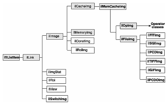
Figure 2-1 shows the portion of the IL class hierarchy that derives from ilLink. These classes provide much of the functionality and flexibility of the ImageVision Library.
The foundation classes shown in shaded boxes in Figure 2-1 are abstract classes and cannot be used directly. Understanding the capabilities these classes provide is key to understanding how the IL works and how to use it. Also, if you extend the IL to meet your specific image processing needs, you will derive your own classes from these abstract classes.
The IL allows you to access, manipulate, store, and display images. You can perform a series of operations on one or more images by creating a chain of operators and passing the image or images down this chain. An operator is a class derived from ilOpImg (the base class for all IL operators) that applies its image processing algorithm to an image. The image output from each operator becomes the input to the next operator in the chain.
An element in a chain of operators can be:
an image file, for example, an ilFileImg object
a processing operation, which generates an image from one or more input elements, for example, an ilAddImg object
an object containing statistical information about an image, for example, an ilImgStat object
a region of interest (ROI), used to restrict the scope of an operator to a sub-portion of its input elements, for example, an ilRectRoi object
a subsection element, which selects a portion of its input(s) to be produced as an output, for example, an ilSubImg or ilSwitchImg object
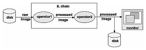
The result of a chain of operations is either a display of the processed image or a file on disk containing the processed image. Figure 2-2 illustrates this concept by showing a generalized image processing chain whose elements are raw and processed images.
The ilLink class implements the chaining model by defining the mechanism for linking the image objects together. This model defines the concept of parent (input) and child (output) images.
The ilLink class also provides functions that allow you to manipulate image attributes by providing functions that keep track of whether an attribute is allowed to change or has been altered. For more information about chaining operators, see “The IL Execution Model”.
The ilImage class is the root for the majority of the IL's image class hierarchy. It provides the IL's abstract concept of what images are and how they are manipulated. The IL defines an image as a four-dimensional array of pixels, x, y, z, and c. An image has certain attributes, such as the size (in pixels) of the image, the data type of the pixel elements (for example, float or int), and the color model that should be used to interpret the data (for example, RGB or CMYK).
The ilImage class provides two main categories of functions to support this abstraction of an image:
image attribute functions, for querying an image about its attributes and setting these attributes (Programmers can explicitly set some attributes, even though many attributes are determined at the time the image is instantiated.)
data access functions, for reading, writing, and copying image data
All classes that derive from ilImage (see Figure 2-1) inherit these general capabilities for querying and setting attributes and accessing data. Thus, the IL allows you to manipulate all images in the same way, regardless of the actual source or destination of the data. The same mechanism is used for data that is associated with any type of image, for example:
Classes derived from ilImage implement their own versions of the data access functions as necessary to add specificity. For example, ilMemCacheImg defines versions of the data access functions that read data from or write data to a partial copy of the image buffered in main memory. Similarly, ilTIFFImg adds capabilities specifically for reading and writing TIFF file headers and data. The ilSharpenImg class incorporates a sharpening algorithm into its access functions.
In the IL, an image has many descriptive attributes. These include:
image size
data type of image pixels
data ordering of channels in an image
color model
color palette
image type
orientation
fill value
minimum and maximum pixel values
data compression
page border
image format
Many of these attributes are assigned default values when an image is created. Some of them are changed subsequently, usually as a result of applying—or preparing to apply—an image operator. Some can be changed explicitly by the programmer. Each class that derives from ilImage chooses which attributes it allows to be explicitly modified. (For more information about how this mechanism works, see “Propagating Image Attributes” and “Managing Image Attributes”.)
This section describes the image attributes and the functions available for retrieving and setting them. These functions are defined by the ilImage and ilLink classes and therefore can be used on any type of image.
Table 2-1 provides a summary of the image attribute functions. All of these functions are described later in this section except for the image format (described in “Querying a File Image”) and the page border (described in “Page Borders”).
Table 2-1. Image Attribute Summary
In addition to the functions shown above, which allow you to set image attributes individually, you might decide to use the IL's ilConfig class, which allows you to specify several image attributes at once. An ilConfig object contains several elements that describe pixel data: the data type, pixel ordering, number of data channels, ordering of data channels, channel offset, orientation, and zoom factors. This class is defined in the header file il/ilConfig.h and described in more detail in “iflConfig” as well as in its reference page.
As you read the following sections, you will note that many of the functions described return a value of data type ilStatus. This enumerated type, which is defined in the header file il/ilError.h, contains the error codes used by the IL to indicate that an unexpected result occurred. If no unexpected result occurred, an image's status is ilOKAY. The error codes and their meanings are listed in “Error Codes”.
At any point, you can query an ilImage about its current status by using getStatus(), a function defined in ilLink that takes no arguments and returns a value of type ilStatus. You can also set an image's status to ilOKAY by using clearStatus() (a function defined in and inherited from ilLink).
One key attribute of an image's its size, which is determined initially when an image is created. In Example 1-1 in Chapter 1, “Writing an ImageVision Library Program,” the size of the image data is determined when the ilFileImgOpen() function is called. An image's size can be described with an iflSize data structure, which consists of four integers that correspond to the image's size in the x, y, and z dimensions and the number of data channels, c, per pixel.
The x and y dimensions specify the width and height of the image as measured in pixels. The z dimension, or “depth,” may refer to the number of xy planes of image data. The xy planes are usually related in some way; for example, they might be a time-series of a single animation scene or a set of CAT scan images. (CAT stands for computerized axial tomography, a medical imaging technique used to create three-dimensional images.) Different image representations require different numbers of data channels to describe each pixel of data. An RGB (red, green, blue) image, for example, requires three channels, one for each of the three colors.
The ilImage class defines functions for retrieving the entire iflSize structure for an image at once and functions for returning each of the elements separately:
You can change an image's size by applying an image operator that affects its size or by setting its size explicitly (if you are allowed to set it). For example, in most cases, the ilRotZoomImg operator produces a processed image with a size that differs from that of the original image, as shown in Figure 2-3:
You can set an image's size explicitly by using setSize(), which takes a reference to the desired iflSize structure as an argument. A separate function, setCsize(), allows you to restrict the number of channels associated with an image.
An image's pixel components must all be of the same data type. The IL defines an enumerated set of data types (iflDataType) and a function, getDataType(), to return the data type of an image's pixels:
iflDataType imgType; imgType = myImg.getDataType(); |
The iflDataType returned can be one of the following: iflBit, iflChar, iflUChar (an unsigned char), iflShort, iflUShort, iflLong, iflULong, iflFloat, or iflDouble. (These types are defined in the il/iflDataTypes.h header file and listed in “Describing Image Attributes”.)
Use isSigned() to query an ilImage about whether its data type is signed:
int sign = myImg.isSigned(); |
As shown, this function takes no arguments and returns TRUE (nonzero) if the image's data type is signed and FALSE (zero) otherwise.
Operators accept input images of any data type. Internally, however, operators may use a different data type than the input data type to process the image. In this case, the data is converted as needed to perform the computation. If you know what data type you need at the end of the computation, you can use the setDataType() function to force the data type.
The channels composing an image's pixel data can be ordered in three ways: iflInterleaved, iflSequential, or iflSeparate. These are the three possible return values of the enumerated type, iflOrder. To return the data ordering, use its member function, getOrder(), as follows:
iflOrder imgOrder; imgOrder = myImg.getOrder(); |
The meanings of the three orders are illustrated in Figure 2-4.
| Interleaved | In interleaved ordering, all pixel components are clustered together. For an interleaved RGB image, data is stored as: RGBRGBRGB.... | |
| Sequential | With sequential ordering, each component is stored as a separate line. In the example, three lines of data (one each for red, green, and blue data) are needed to describe one line of pixels. | |
| Separate | An image using separate ordering stores each component in a separate page. (See “The Cache” for more information about pages.) |
Thus, the order defines that dimensions that vary most rapidly relative to the others in a chunk of data. For example, in the interleaved case, the channel dimension varies most rapidly, and the z dimension varies least rapidly. Here is how the dimensions vary for each of the orders, listed from most to least rapidly: iflInterleaved (c,x,y,z), iflSequential (x,c,y,z), iflSeparate (x,y,z,c).
In the rare cases where you need to set an image's order, use the setOrder() function. Some classes derived from ilImage, such as ilFileImg, do not let you change an image's order.
An image's color model determines the meaning of the data channels from which a pixel is constructed. The IL defines an iflColorModel enumerated type (in the header file il/iflDataTypes.h) that can refer to the following color models:
The getColorModel() function allows you to query an image about its color model. If necessary, you can change the data interpretation by using the setColorModel() function.
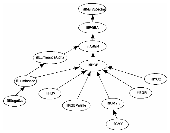
If an application or derived class does not use the setColorModel() function to explicitly set the color model of an ilOpImg object, the color model defaults to the lowest common ancestor of the input images as shown in Figure 2-5:
All classes derived from ilOpImg have specified output data types, data ordering, working data types, and fields that can be set on an object. You can identify them by finding the following functions in each class: setValidType(), setValidOrder(), setWorkingType(), and setAllowed(), respectively. For example, the ilWarpImg operator uses an iflUChar as the output data type, can use any output ordering, uses iflFloat as the working type, and can have any of its fields set.
You can set the data type or data order explicitly to a valid type or ordering by calling the ilImage member function setValidType() or setValidOrder(), respectively. If the data type or order is not set explicitly in this manner, they default to the “smallest” of the valid types or ordering that is at least as “great” as each input type or order. Here “small” and “great” refer to the numeric values of the types and ordering, as defined in il/iflDataTypes.h.
An ilOpImg object has a “working type”, which is the data type used for calculations. The working type is often the same as the output data type. When this is not the case, the setWorkingType() function is used to define the working types.
The setAllowed() function specifies which fields can be set on an object that is an instance of a class derived from ilOpImg.
Some images include a color palette that is used to interpret their data. A color palette is also referred to as a lookup table or LUT. The most common use of such a table is to store color map values. The iflLut class, defined in the header file ifl/iflLut.h and described in “Using iflLut”, is provided for such purposes. To set an image's LUT, use setColorMap():
ilStatus setColorMap(const iflLut& lut); |
The table pointed to by lut is established as the image's look-up table. This function copies the specified iflLut but not its data. The getColorMap() function returns by reference an image's LUT:
void getColorMap(iflLut& lut); |
Two other functions—iflSGIColormap() and ilSGIFileLut()—create look-up tables for use in managing color map data. They are described in “Using iflLut” and in their own reference pages.
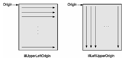
Different file formats arrange their data in different ways. By default, a TIFF file image considers its origin to be the upper left corner; if you scan through the data, you should read from left to right, working your way down the image. An SGI RGB image considers its origin to be the lower left corner; to read through its data, again read from left to right, but work your way up the image.
The IL defines an iflOrientation data type to represent the possible orientations of image data. To query an image about the orientation of its data, use getOrientation(), which returns one of the eight values listed below. (You can set an image's orientation with the setOrientation() function.) These four orientations use the traditional orientation of the x and y dimensions (the x dimension runs horizontally, and the y dimension runs vertically):
iflUpperLeftOrigin | The origin is in the upper, left corner and you read data from left to right, working your way down the image |
iflLowerLeftOrigin | The origin is in the upper, left corner and you read data from left to right, working your way up the image |
iflUpperRightOrigin | The origin is in the upper right corner, and you read data from right to left, working your way down the image |
iflLowerRightOrigin | The origin is in the lower right corner, and you read data from right to left, working your way up the image |
The following four orientations have the x and y dimensions transposed so that the x dimension runs vertically, and the y dimension runs horizontally.
iflLeftUpperOrigin | The origin is in the upper left corner, and you read from top to bottom, working your way across the image to the right. |
iflLeftLowerOrigin | The origin is in the lower left corner, and you read from the bottom to the top, working your way across the image to the right. |
iflRightUpperOrigin | The origin is in the upper right corner, and you read data from top to bottom, working your way across the image to the left. |
iflRightLowerOrigin | The origin is in the lower right corner, and you read data from bottom to top, working your way across the image to the left. |
Figure 2-6 illustrates the difference between iflUpperLeftOrigin and iflLeftUpperOrigin orientation of image data.
When a function tries to access pixels that are beyond an image's edge, those pixels are set to the image's fill value. By default, an image's fill value is 0, but you can set a different fill value with the setFill() function:
static float fillData[3] = {127.0, 127.0, 127.0};
myImg.setFill( iflPixel(iflFloat, 3, fillData) );
|
As shown, setFill() takes a reference to an iflPixel as an argument. An iflPixel defines the pixel is data type (in this case, iflFloat), the number of data channels (3), and the pixel data itself (fillData[]). (In this example, the iflPixel value is passed in-line so that the compiler automatically constructs and deletes the object.) The image makes its own copy of the pixel data.
Use getFill() to query an image about its fill value:
iflPixel theFillValue; myImg.getFill(theFillValue); |
You use the allocFillData() and freeFillData() functions in the ilImage class to create and free fill values in the native image format from an RGB triplet. The functions are defined as follows:
void* allocFillData(float red, float green, float blue); void freeFillData(void* data); |
By default, no restrictions are placed on the range of allowable pixel values. However, when an image is displayed—for example, using the ABGR color model—its pixel values may need to be converted to the range that is meaningful for the framebuffers, which is 0 to 255. If you explicitly set an image's minimum and maximum allowable pixel values, they are used to color-scale the data as it is displayed.
You might want to set the allowable pixel values for a processed image so that the resulting data has certain characteristics, especially if you display the data. For example, suppose you are using an edge detection filter that theoretically produces data ranging in value from -1000 to +1000. However, you know that the images you'll be filtering will actually yield filtered data ranging from -100 to +100. If you set the allowable values to match this range and then display the filtered data, the display will be more useful, since the data will be scaled and stretched out over the framebuffer is meaningful range.
Minimum and maximum values are image attributes that are stored with an image. You can set the minimum and maximum allowable values for an image's pixel data by using the setMinPixel() and setMaxPixel() functions. Both these functions take an ilPixel reference as an argument:
ilStatus setMinPixel(const ilPixel& pix); ilStatus setMaxPixel(const ilPixel& pix); |
Use getMinPixel() and getMaxPixel() to query an image about its minimum and maximum allowable pixel values:
void getMinPixel(ilPixel& pix); void getMaxPixel(ilPixel& pix); |
These functions return the minimum or maximum pixel value by reference.
You can also set the minimum and maximum values for an individual channel of an image:
ilStatus setMinValue(double val, int c=0); ilStatus setMaxValue(double val, int c=0); |
These functions set channel c's minimum or maximum value to val.
To query an image about its channel value limits, use getMinValue() and getMaxValue():
double getMinValue(int c=-1); double getMaxValue(int c=-1); |
These functions return the minimum or maximum allowable value for the specified channel (the default, -1, returns the minimum or maximum of all channels).
Minimum and maximum scaling values are used by the IL during color conversion. By default, the scale minimum and maximum are the same as the image minimum and maximum values. The IL provides functions you can use to set and retrieve maximum and minimum scaling values.
The initScaleMinMax() function initializes the scale minimum and maximum to the image minimum and maximum values. If scale minimum and maximum have already been set, they are unchanged, unless force is TRUE.
void initScaleMinMax(int force=0); |
The function setScaleMinMax() sets the minimum and maximum scaling values to min and max. The setScaleType() function sets the scale minimum and maximum to the minimum and maximum values of the data type passed in type.
ilStatus setScaleMinMax(double min, double max); ilStatus setScaleType(iflDataType type = iflDataType(0)); |
The getScaleMax() and getScaleMin() functions return the maximum and minimum values used for scaling during color conversion.
double getScaleMax(); void getScaleMin(); |
Often, images stored in a file on disk are compressed to minimize their size. Such images need to be decompressed before they can be read. There are many different compression algorithms. Each file format (for example, TIFF) determines which algorithms it supports. See “Setting a File's Compression” for more information about which compression algorithms the IL supports. From a programmer's point of view, as data is read or written in an IL program, its compression or decompression is handled transparently.
The IL uses the term cache to mean a portion of memory that holds raw and processed image data that can be accessed by a process. This is not the same as the hardware cache that is accessed by the CPU. The IL cache holds image data in rectangular pieces called pages. The cache does not necessarily hold all the pages for each image being processed, but only those pages that have been referenced and have not been bumped out of the cache to make room for more recently-referenced pages. Thus, only part of an image may reside in the cache.
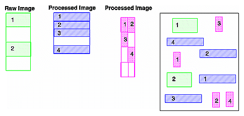
Figure 2-7 shows a cache that contains three images being used by an IL application. The three rectangles on the left show a logical map of the pages for each image. The shaded boxes indicate the pages of each image resident in the cache. For example, the raw image contains four pages, only two of which are in the cache. The rectangle on the right shows the cache as it might contain the pages from the three images.
The IL keeps track of the pages in the cache, brings in a page when the program requests data on a page not in the cache, and chooses a page to be overwritten when additional room is needed in the cache.
Every IL class that derives from ilMemCacheImg uses the cache and the caching mechanism defined by ilMemCacheImg. Both ilOpImg and ilFileImg inherit directly from ilMemCacheImg and use caching in these ways:
IL operators (those classes that derive from ilOpImg) use the cache to hold their output.
Classes that derive from ilFileImg place raw, uncompressed data in the cache.
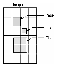
While the cache holds image data in pages, an IL program can access image data in rectangular blocks of any size, without regard to page boundaries. These rectangular blocks are referred to as tiles. As shown in Figure 2-8, tiles can cross page boundaries or can be smaller than a page.
When a program requests a data tile, the IL checks the cache. If the data corresponding to the tile is not among the pages already in the cache, the IL brings additional pages into the cache as necessary. If the cache is already full, it must discard some of the resident pages in order to make room for the new pages. The page replacement algorithm is based on a combination of the following factors:
The number of times each page has been referenced; the more times a page is referenced, the more likely it will remain in the cache.
The priority of the references; higher priority requests tend to have their pages retained longer.
The relative time since each page was last referenced; the pages that have been in the cache the longest without being referenced are discarded first.
The overall effect of the page replacement algorithm is that data toward the end of a chain tends to get preferentially cached. Other data that is frequently referenced (for instance, the input to an operator whose parameters are being repeatedly adjusted) also tends to remain in the cache. To prevent data from being recomputed for successive tile requests, the cache must be large enough so that pages just discarded aren't reread. (See the following two sections for more information on setting the size of the cache and adjusting priorities.)
Since operators place processed image data in the cache, data is operated on as it is brought into the cache. To maximize efficiency under this execution model, only the pages needed to satisfy any given tile request are brought into the cache. For example, if a getTile() request specifies only a single channel of an image that is stored in a separate format, only the pages containing that channel are accessed. Thus, processing multispectral data (or any data stored in a separate format) is made as efficient as possible.
By default, the cache size is set to 30% of the total user memory on the host system. The IL provides two functions to override the default size of the cache, ilSetMaxCacheSize() and ilSetMaxCacheFraction(), which are defined as shown below:
void ilSetMaxCacheSize(int maxBytes); void ilSetMaxCacheFraction(float fraction); |
The first function sets the cache size to the number of bytes indicated. The second function computes the size of the cache as the indicated fraction of the total user memory on the host computer.
You can change these limits without modifying an IL- based program by using the environment variables IL_CACHE_SIZE or IL_CACHE_FRACTION to set either the size in bytes or the fraction of user memory, respectively. The IL_CACHE_SIZE value overrides the value specified by IL_CACHE_FRACTION. Any value established with these environment variables is overridden by calls to ilSetMaxCacheSize() or ilSetMaxCacheFraction().
The current value of these cache size limits can be obtained with either ilGetMaxCacheSize() or ilGetMaxCacheFraction(). The current actual size of the object is cache can be retrieved with ilGetCurCacheSize(). These functions are defined as follows:
int ilGetCurCacheSize(); int ilGetMaxCacheSize(); float ilGetMaxCacheFraction(); |
The IL maintains the global cache in a special memory pool that allows the cache memory to be compacted to eliminate memory fragmentation problems. When fragmentation exceeds a defined threshold, the pool is automatically compacted. You can use the ilSetCompactFraction() function to set the fragmentation threshold to the maximum fraction of the pool that is allowed to be wasted space before compaction occurs. The current value of this threshold can be obtained with ilGetCompactFraction(). The default compaction fraction value is .2 or 20%.
ilSetCompactFraction(float maxWastedFraction); float ilGetCompactFraction(); |
You can force compaction of the pool at any time by calling ilCompactCache(). If the pool is more fragmented than the fraction passed to this routine, it is compacted. You can pass zero to cause the pool to be unconditionally compacted.
ilCompactCache(float maxWastedFraction=0); |
You can use the getCacheSize() function of ilMemCacheImg to query the cache size for an individual object:
int getCacheSize(); |
You can use the flush() member function of ilMemCacheImg to flush the cache for an individual object:
ilStatus flush(int discard=FALSE)); |
You can free the memory in the global cache to get it down to a desired maximum size with ilFlushCache(). This call also compacts the cache memory.
int ilFlushCache(int maxsize); |
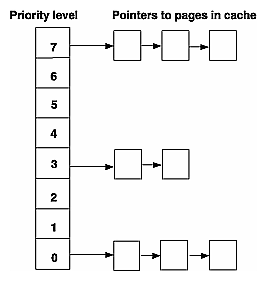
The IL assigns priorities to pages in the cache and uses these priorities to make decisions about which pages to discard. The priority associated with pages in cache ranges from zero (lowest) to seven (highest); the higher the priority, the greater the likelihood the page will remain resident.
The IL maintains a linked list of the pages in cache for each of priority levels 0 through 7. Figure 2-9 illustrates this concept. This simplified diagram shows a cache with three pages at priority level seven, two pages at priority level three, and three pages at level zero.
The initial (default) priority level of a page is zero. The following events can cause a change to the priority level:
The priority of a page is incremented each time the page is accessed (for example by a copyTile() or ilMemCacheImg::executeRequest()). This is essentially a reference count; the more times a page is referenced, the higher its priority.
The priority of the page is incremented when you use the lockPage() method to lock a page.
If you use the setPriority() method to set the priority of the image containing the page, the IL increases the priority of the page by one plus the value specified in setPriority() each time the page is referenced. The setPriority() definition is shown below:
void setPriority(int priority);
The maximum number of pages at each priority level is one eighth of the total number of pages in cache. If the number of pages at any one priority level exceeds this limit, the priority level of the last page at that level is reduced by one. In other words, the page is moved to the head of the list at the next lower priority level.
You can use the ilmonitor utility to monitor the activity of pages in cache. See the ilmonitor reference page or “Image Tools” for more information about ilmonitor.
The page size for each operator is defined by its input images. For an ilFileImg, the page dimensions match those used to store the image on disk. Some images also let you set the size of the pages in the cache, the data type, and the ordering of the cached data. The data type and ordering affect how data is cached, so if you change these attributes, you might also want to change the size of the cache. To set the data type or the ordering of data in the cache, use the appropriate functions defined by ilImage, setDataType() and setOrder(). These functions are described in “Image Attributes”. “Managing Cache” describes how to set the size of the cache.
Only image operators allow you to set the page size of an image. If you change the page size of an image, you should follow the suggestions in “Cache Priority”.
To set the size of the pages used in the cache for a particular image, use setPageSize(), which is defined in the ilImage class as follows:
ilStatus setPageSize(int nx, int ny, int nz, int nc)
    { return setPageSize(iflSize(nx, ny, nz, nc)); }
ilStatus setPageSize(const iflSize& pageSize);
ilStatus setPageSize(int nx, int ny);
|
The following functions are related:
ilStatus setPageSizeZ(int nz); ilStatus setPageSizeC(int nc); |
The arguments specify the x, y, z, and c dimensions of the page in pixels. This function calculates the number of bytes needed to store a page with the specified dimensions.
You can use any of the following functions to query an image about its page size, depending on whether you want the answer in page dimensions, bytes, or pixels:
size_t getPageSize(); size_t getPageSize(int& nx, int& ny, int& nz, int& nc); size_t getPageSize(int& nx, int& ny) size_t getPageSize(iflSize& pageSize, iflOrientation workOrientation); size_t getPageDimensions(iflSize& pageSize) int getPageSizePix(); int getPageSizeVal(); |
The ilImage class provides functions to support paging in a multi-threaded environment. These functions allow you to lock pages to ensure that those pages stay in memory until you unlock them. The five virtual functions that control paging are:
virtual int hasPages();
virtual ilPage* lockPage(int x, int y, int z, int c,
          ilStatus& status, int mode=ilLMread);
virtual void unlockPage(ilPage* page);
ilStatus lockPageSet(ilLockRequest* set,
          int mode=ilLMread, int count=1);
void unlockPageSet(ilLockRequest* set, int count=1);
|
These methods provide a mechanism to bypass the overhead of getTile() and setTile(), but they require that you consider all of the attributes of the page: size, data type, and order.
All classes derived from ilImage read, write, and copy image data using the same set of data access functions defined by the ilImage base class. Each derived class implements the functions as necessary to suit its particular requirements. A key feature of these functions is that they allow you to access any arbitrary rectangle, or tile, of image data, regardless of how that data is stored. This flexibility allows the IL is demand-driven execution model to be implemented. As part of this model, calls to some of these functions are generated automatically. However, you can also call these functions explicitly as needed. The execution model is discussed in detail in “The IL Execution Model”. The ilImage class defines both three-dimensional and, for convenience, two-dimensional data access functions, as shown in Table 2-2.
Table 2-2. Data Access Functions
Three-dimensional | Two-dimensional | Description |
|---|---|---|
getTile3D() setTile3D() copyTile3D() or << [a]copyTileCfg() | getTile() setTile() copyTile() or << | reads, writes, and copies a tile of data |
getSubTile3D() setSubTile3D() | getSubTile() setSubTile() | reads and writes a subtile of data |
getPixel3D() setPixel3D() | getPixel() setPixel() | reads and writes a pixel |
fillTile3D() | fillTile() | fills a tile with a constant value |
[a] << is the left-shift or output operator; it is redefined in the C++ version of the IL. | ||
The two-dimensional data access functions work through their three-dimensional counterparts. Since the two-dimensional versions are slightly easier to comprehend, they are discussed first, in the next section.
The two-dimensional functions you are likely to use most frequently are getTile(), setTile(), and copyTile(). As their names suggest, these functions read (get), write (set), and copy a tile of data. They assume the data buffer being read into or written from is the exact size necessary to hold the tile being read or written; if the buffer is larger use getSubTile() or setSubTile().
Another pair of functions, getPixel() and setPixel(), allow you to read and write pixels rather than tiles. The fillTile() function allows you to fill a two-dimensional tile of data with a specified constant value.
The calling sequences for getTile() and setTile(), which take the same arguments, are shown below:
ilStatus getTile(int x, int y, int nx, int ny,
    void* data,const ilConfig* config=NULL);
ilStatus setTile(int x, int y, int nx, int ny, void* data,
    const ilConfig* config=NULL);
|
getTile() retrieves a tile of data from a source image and places it in the location pointed to by data. This source image is the one whose getTile() function is called. The tile that is retrieved is specified by its origin in the source image (x,y) and its size (nx and ny), which is measured in pixels. (Since the tile's origin is specified in the image's orientation, the (x,y) point is specified relative to the image's origin.) The optional config argument allows you to change the configuration of the data (including the orientation) as it is read and placed in the buffer. If this argument is not supplied, the configuration of the source image is used. One element of an ilConfig object is an ordered list of the image's channels. See “copyTile()” for an example of using this channel list to reorder channels as data is retrieved.
The setTile() function writes a tile of data from the location pointed to by data to the destination image. The location of the tile being written is specified by its origin in the destination image (x,y) and its size (nx and ny). The optional config argument for setTile() describes the configuration of the data being written; if necessary, the data is automatically reconfigured to match the configuration of the destination image. If this argument is not supplied, it is assumed that the data being written already has the same configuration as the destination image.
The copyTile() function is an efficient way to copy a tile of data from one ilImage to another:
ilStatus copyTile(int x, int y, int nx, int ny, ilImage* image, int ox, int oy, int* chanList=NULL); |
The tile is copied to the location (x, y). (nx, ny) specifies the size of the tile. (ox, oy) specifies the location in the source image from which the data is copied. (If the tile is at the same location in both the source and destination images, then x=ox and y=oy.) If the source and destination images have different orientations, the data is transposed automatically as necessary.
No configuration argument is needed for copyTile() because the destination image's configuration is always used. Data is automatically converted as necessary to match the destination image's data type, order, and orientation. However, you can choose a subset of the source image's channels and/or reorder them using the optional chanList argument. This argument is an int array that specifies a channel mapping between the other image and the calling image. The number of entries in the array should always match the number of channels in the calling image; a negative one (-1) in the array means that no data will be written for that channel.
As an example, suppose you have an RGB image (with red, green, and blue channels) that you want to display as an ABGR image (with alpha, blue, green, and red channels). The code for accomplishing this conversion is:
/* allocate the data buffer */
int xsize = 20;
int ysize = 10;
char data[xsize*ysize*3];
/* specify the channel list and configuration */
static int chans[] = {3, 2, 1};
ilConfig config(iflUChar, iflInterleaved, 3, chans);
/* read the data from one image and write it to the other */
RGBImg.getTile(0, 0, xsize, ysize, data);
ABGRImg.setTile(0, 0, xsize, ysize, data, &config);
|
| Note: You can do this conversion most simply with the color conversion operators that derive from ilColorImg, but this example using getTile() and setTile() is presented for discussion purposes. |
First, a buffer, data, is allocated to hold the 20-pixel by 10-pixel three-channel tile as it is copied. Next, the configuration that the data should be mapped into is specified. The channel list, chans, maps the channels of the RGB data to the channels of the ABGR image, as follows:
Channel 0 of the RGB data (the red channel) is mapped to channel 3 of the ABGR image (also the red channel).
Channel 1 of data (green) is mapped to channel 2 of the ABGR image (also green).
Channel 2 of data (blue) is mapped to channel 1 of the ABGR image (blue).
Nothing is available to map to channel 0 of the ABGR image (the alpha channel).
Finally, the data is read into the buffer from RGBImg and then it is written to ABGRImg from the buffer.
The following code performs the same task using copyTile() instead:
int xsize = 20;
int ysize = 10;
static int chans[] = {-1, 2, 1, 0};
ABGRImg.copyTile(0, 0, xsize, ysize, RGBImg, 0, 0, chans);
|
In this case, an intermediate data buffer is not needed; the tile is copied directly from RGBImg to ABGRImg. The channel list specifies how the channels of RGBImg are mapped to those of ABGRImg, as shown in Table 2-3.
Channel List | RGBImg Channel | ABGRImg Channel |
|---|---|---|
-1 | none | 0 (alpha) |
2 | 2 (blue) | 1 (blue) |
1 | 1 (green) | 2 (green) |
0 | 0 (red) | 3 (red) |
The interpretation of the channel list is the same if the direction of the copy is reversed. If the same channel list were used with a call to copyTile() that specified 0 as the direction argument, data would be copied from ABGRImg to RGBImg as follows:
Channel 0 of ABGRImg is not copied at all.
Channel 1 of ABGRImg is copied to channel 2 of RGBImg.
Channel 2 of ABGRImg is copied to channel 1 of RGBImg.
Channel 3 of ABGRImg is copied to channel 0 of RGBImg.
If you need to offset channels, you must use copyTileCfg() instead of copyTile(). copyTileCfg() is discussed in “Three-dimensional Functions”. To force a two-dimensional interpretation of copyTileCfg(), specify zero values for the z, nz, and oz parameters.
The C++ language allows you to overload the definition of operators as long as the arguments of the constructors are different. The IL overloads the operator << so that it requires a reference to an ilImage as an argument and so that it becomes a shorthand for copyTile(). Here is how you invoke this operator (assume the two ilImages srcImage and destImage are already created):
destImage<<srcImage; |
This operator copies srcImage's data to destImage, aligning the data with destImage`s origin. If the two images are different sizes, the size of destImage is equal to the smaller of destImage or srcImage.
The << operator works for two- and three-dimensional images.
One limitation of getTile() and setTile() is that the data buffer must be the exact size needed to hold the data being read or written. If the buffer you are reading data into or writing it from is larger than the tiles being read or written, use getSubTile() or setSubTile() to specify a subtile of the larger buffer. (Be sure the buffer is at least as large as the tile being read or written and that the tile is completely contained in the buffer.) The calling sequences for these functions are as follows:
ilStatus getSubTile(int x, int y, int nx, int ny, void* data,
               int dx, int dy, int dnx, int dny,
               const ilConfig* config=NULL);
ilStatus setSubTile(int x, int y, int nx, int ny, void* data,
               int dx, int dy, int dnx, int dny,
               const ilConfig* config=NULL);
|
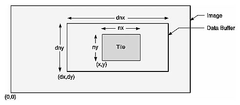
The x, y, nx, ny, data, and config parameters have the same meanings as they have in getTile() and setTile(). The remaining parameters specify the origin of the data buffer (dx,dy) relative to the image and the size of the buffer (dnx and dny), as shown in Figure 2-10. (This figure assumes that the image's orientation defines the origin as the lower left corner.)
With either function, if the data buffer is the same size as the source tile, then x=dx, y=dy, nx=dnx, and ny=dny.
If you would rather read or write pixels than tiles, use getPixel() or setPixel():
ilStatus getPixel(int x, int y, ilPixel& pix); ilStatus setPixel(int x, int y, ilPixel& pix); |
These functions read or write the pixel at location (x,y) in the calling image. When a pixel of data is read, it is placed in the location referenced by pix. The pix argument for setPixel() references the data that is written into the calling image at (x,y).
As a special case of writing a tile of data, you can set an arbitrary rectangular area of an image to a constant value with fillTile():
ilStatus fillTile(int x, int y, int nx, int ny,
              const void* data, const ilConfig* config=NULL,
              const iflTile3Dint* fillMask=NULL);
|
The rectangular area to be filled is specified by its origin (x,y) and size (nx and ny), measured in pixels. The data argument specifies the value used to fill the tile; it is typically an iflPixel object (for C++ programmers). For example, to fill a tile with white, use an iflPixel with these values: 255, 255, 255. The optional config argument describes the configuration of data. If it is omitted, data is assumed to have the same configuration as the image being filled.
The last argument, fillMask, allows you to define a mask that prevents a portion of the tile from being filled. (See “Auxiliary Classes” for a detailed description of the iflTile class.) If it is not NULL, only the portion outside of the fillMask is filled.
The three-dimensional data access functions are the same as their two-dimensional counterparts, except that they take extra arguments as necessary to handle an image's z dimension. For example, getTile3D(), setTile3D(), and copyTile3D() take arguments to specify the origin and size in the z dimension:
ilStatus getTile3D(int x, int y, int z, int nx, int ny,
        int nz, void* data, const ilConfig* config=NULL);
ilStatus setTile3D(int x, int y, int z, int nx, int ny,
        int nz, void* data, const ilConfig* config=NULL);
ilStatus copyTile3D(int x, int y, int z,
        int nx, int ny, int nz,
        ilImage* image, int ox, int oy, int oz,
        int* chanList=NULL);
|
The copyTileCfg() function works similarly to the copyTile3D() function, except that it allows the channels of the copied data to be offset as well as reordered when it is copied:
virtual ilStatus copyTileCfg(int x, int y, int z,
        int nx, int ny, int nz,
        ilImage* image, int ox, int oy, int oz,
        const ilConfig* config=NULL);
|
| Note: This function takes an ilConfig* argument rather than an int*. Only fields in the ilConfig that refer to the number of channels, channel list, and channel offset are used during the copy; the other fields are ignored. |
The getSubTile3D() and setSubTile3D() functions require several additional arguments to specify the origin and size of the z dimension in both the source and the destination:
ilStatus getSubTile3D(int x, int y, int z,
        int nx, int ny, int nz,
        void* data, int dx, int dy, int dz,
        int dnx, int dny, int dnz,
        const ilConfig* config=NULL) = 0;
ilStatus setSubTile3D(int x, int y, int z,
        int nx, int ny, int nz,
        void* data, int dx, int dy, int dz,
        int dnx, int dny, int dnz,
        const ilConfig* config=NULL) = 0;
|
The fillTile3D() function takes arguments that are similar to the two-dimensional versions:
virtual ilStatus fillTile3D(int x, int y, int z,
        int nx, int ny, int nz,
        void* data, const ilConfig* config=NULL,
        const iflTile* fillMask=NULL);
|
This section discusses a few functions designed to perform tasks related to accessing data. getStrides() helps you step through a buffer of image data. clipTile() clips a tile to the dimensions of the image.
In some situations, you might want to step through a buffer of image data pixel by pixel, rather than simply reading or writing a single tile of data. Or you might want to move some specific number of pixels in a particular direction. To do this, you need to know where one pixel's data ends and the next one's begins. This information, called the stride, depends on the image's data type, pixel ordering, and the size of the data buffer. getStrides() returns data strides by reference:
void getStrides(int& xs, int& ys, int& zs, int& cs, int nx=0, int ny=0, int nz=0, int nc=0, iflOrder ord=iflOrder(0)); |
You specify the size of the data buffer, nx, ny and nz, and the pixel ordering, ord. The default value, iflOrder(0), means that the calling image's ordering should be used. The remaining values are returned by reference:
xs, the x stride, steps to the next pixel in the same row.
ys, the y stride, steps to the next pixel in the same column.
zs, the z stride, steps to the next pixel along the z axis at the same xy location.
cs, the channel stride, steps to the next channel of the same pixel.
nc is the number of channels in the data.
Another useful function, clipTile(), clips a specified tile to an image's boundaries:
ilStatus clipTile(int& x, int& y, int& z,
        int& nx, int& ny, int& nz, int includeBorder=FALSE);
|
The arguments specify, by reference, the origin (x, y, z) and size (nx, ny, nz) of the tile. The includeBorder argument specifies whether the page borders of the image should be used to determine clipping. If includeBorder is TRUE, the clipped tile includes a border at the edge of the image whose size is determined by the IL (or by setPageBorder() if you choose to use this function). If includeBorder is FALSE (which it is by default), the tile is clipped to the actual image edge, not including any borders. If any part of the tile lies outside the image's boundaries, the corresponding argument is adjusted as necessary to clip the tile. You can then use the parameters in a call to getTile() or setTile(), for example. If the tile is clipped, clipTile() returns ilDATACLIPPED; otherwise, it returns ilOKAY.
Several functions are defined to help you translate image data between different orientations:
The mapFlipTrans() function determines the flips and/or transpositions necessary to map coordinates from the fromSpace orientation to workSpace (and returns them by reference). The mapTile() and mapXY() functions map the specified tile or (x,y) point from fromSpace to workSpace. The mapXYSign() function reverses the sign of the (x,y) values if workSpace is flipped with respect to fromSpace; it also swaps the values (that is, exchanges x for y and vice versa) if the orientations are transposed. The mapSpace() function returns the orientation that results from performing the specified flips, transpositions, or both. The other two functions return information related to an image's orientation. The getSize() function maps the image's size to the workSpace orientation and returns it by reference. The isMirrorOrientation() function returns whether otherSpace is a mirror image of workSpace.
For more information about these functions, see the ilImage reference page.
Four functions are defined in ilImage to support image processing operators that perform geometric transformations:
void mapToSource(iflXYfloat& src, const iflXYfloat& self); void mapFromSource(iflXYfloat& self, const iflXYfloat& src); virtual void evalXY(iflXYfloat& xy, const iflXYfloat& uv); virtual void evalUV(iflXYfloat& uv, const iflXYfloat& xy); |
mapToSource() transforms the coordinates in self into the source image's orientation and places them in src. mapFromSource() transforms the coordinates in src into the calling image's orientation and places them in self. evalXY() maps from the calling image's orientation to the immediate input image's orientation. evalUV() maps from the immediate input image's orientation to the calling image's orientation.
This section describes the IL execution model and explains, in general, how it works in an IL program. Features of the IL execution model are:
on-demand processing of image data using chains of IL operators
multi-threading to allow some portions of an IL program to execute in parallel
the use of hardware acceleration whenever possible to improve the performance of operators in an IL chain
The IL incorporates these features into your program automatically. You need to understand them, however, to tune your program for optimum performance.
In the IL's execution model, image data is processed only on demand. This technique minimizes both the need to store intermediate results and the frequency of disk input and output operations so that overall program performance is optimized. IL programs that apply multiple successive image processing operators or that deal with large images especially benefit from this execution model.
| Note: An operator is a class derived from ilOpImg that applies its image processing algorithm to the data encapsulated in an ilImage object. See Chapter 4, “Operating on an Image,” for more information. |
An IL program implements the demand-driven execution model in two stages:
It creates a chain of image processing operators by creating the desired operator classes.
It pulls data through the chain as it is needed. The impetus for pulling data through the processor chain is the need for the image data at the end of the chain, either for display or storage on disk. The data is pulled by processing one to several pages at a time.
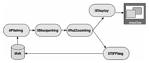
In Example 1-1, a relatively simple image chain is constructed. Figure 2-11 shows this chain with arrows indicating the path that image data follows as it is read from disk, processed (sharpened and rotated), displayed, and written to disk.
An image processing library that uses the conventional execution model shuffles data in and out of memory at each stage of the chain. Such a program:
Reads the initial image data from disk into a buffer.
Sharpens it.
Writes the sharpened data into a different buffer.
Rotates the sharpened data.
Writes the final, processed data into another buffer.
Writes the final data into the framebuffer and back to disk.
If the image is too large to be cached in memory, a conventional library will write at least some of the processed data to disk for each intermediate stage. This data then needs to be read back in from disk for each successive stage.
In contrast, the IL pulls one or several pages of image data at a time all the way through the chain. After a page is completely processed—in this example, read from disk, sharpened, rotated, displayed, and written to a file on disk—the next page is pulled through the chain. When multi-threading is enabled, several pages can be in process through the chain at any one time. This execution model eliminates the need to save intermediate processing results for all images, regardless of their size. The IL's model also minimizes startup time for IL programs, particularly those that allow the user to roam around a large image. The data for the entire image is not processed before startup; it is processed only as needed, which, in this case, is as the user roams.
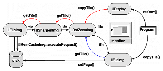
The arrows in Figure 2-12 show how data is pulled through the image chain in Example 1-1.
In this example, the redraw() and copyTile() function calls issued by the program instigate the processing of image data. They cause successive tiles of image data to be pulled through the chain and sent to the display or back to the disk. As each tile is written, another tile is requested from the previous stage of the chain with a getTile(), copyTile(), or ilMemCacheImg::executeRequest() calls. If the tile requested does not already reside in the cache, the page containing that tile is pulled through the chain—read from disk, sharpened, and rotated. The ilDisplay class manages the transfer of data from the end of the chain to the framebuffer.
In Example 1-1 in Chapter 1, “Writing an ImageVision Library Program,” the instigating functions—ilDisplay's redraw() and ilTIFFImg's copyTile()—are actually called in the program. The other function calls are generated automatically as the program executes. Thus, only data that is actually needed is pulled through the chain.
Example 1-1 displays and writes to disk the entire processed image one tile at a time. Other image processing programs might not even process an entire image. For example, suppose that instead of simply displaying the entire final image, a program allows the user to roam around the image, viewing only a fraction of it at a time. This kind of user interface is typically provided with programs that deal with huge images. Since IL programs process data only as it is needed, only those portions of the image that the user demands to see are processed. It is often the case that the user will never view some portions of a large image; those portions are not read from disk or processed. Thus, the IL helps minimize your program's overall processing requirements.
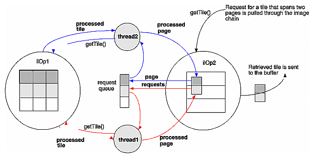
The multi-threading part of the IL's execution model optimizes overall program performance by allowing portions of an IL program to execute in parallel. For example, when a tile covering several pages is copied from one operator to the next in a chain and the tiles are not resident in cache, they must be fetched from disk. The IL implements the parallel fetching of pages by queueing a request for each page and creating a process thread to service each request.
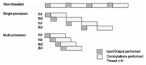
Figure 2-13 shows how long it takes to read in and perform computations on four pages in a non-multi-threaded application, a multi-threaded application running on a single-processor machine, and a multi-threaded application running on a multiple-processor machine. As you can see, the multi-threaded applications complete this transaction more quickly than the non-multi-threaded application.
Figure 2-13. Performance Comparison of Non-threaded, Single-processor, and Multi-processor Applications
 |
IL supports parallel execution on single- and multiple-CPU machines by creating process threads that execute portions of an IL program simultaneously. This multi-threading facility is implemented transparently and automatically: there are no special function calls to make or header files to include. When you derive new classes from the existing classes in the library, however, you must ensure that the code you produce is reentrant, that is, able to be called from several process threads running concurrently. Chapter 7, “Optimizing Your Application,” explains how to do this.
When debugging your application or linking with other libraries that perform multi-threading, you may want to turn off IL's multi-threading facility. The preferred way to do this is to set the environment variables IL_COMPUTE_THREADS and IL_SPARE_THREADS to zero by using the convenience function ilMPSetMaxProcs(), as follows.
ilMPSetMaxProcs(0,0); |
This global function does not belong to any class.
When the IL processes a getTile() or copyTile() call, it determines the pages needed for the requested tile and dispatches a request for each page. It then maintains these requests in a queue and creates process threads to service the queue. Figure 2-14 illustrates the concept of multi-threading as well as the on-demand processing described in the preceding section.
The hardware acceleration facility built into the IL allows your application to automatically take advantage of specialized graphics hardware whenever possible in order to make certain IL operations more efficient. IL does this by performing one or more operations at the end of a chain in the graphics hardware instead of the CPU. On some architectures, it does this by reserving part of the framebuffer as a pixel buffer for IL. Computations are then performed on the data stored in the framebuffer and displayed more quickly than if the data were being operated on in the CPU and brought in from main memory. If the IL needs a tile that is not in the reserved part of the framebuffer, the tile is brought into the framebuffer from main memory. This model is implemented transparently and automatically; there are no header files to include or function calls to make.
Sometimes you need to disable the hardware acceleration facility, for example:
when you are debugging your program. You cannot debug with this facility enabled if the operator you need to test is a CPU operation that is accelerated in the hardware.
when you need more accurate results. Computing some operations in the CPU (for example, those that require a resampling method) gives more accurate results at the expense of speed.
You can enable and disable the hardware acceleration facility:
globally for all features of the IL
for specific objects of an operator class
for all objects of a specified class
“Using Hardware Acceleration” gives detailed information about how to enable and disable hardware acceleration.
Some image processing operations, for example, those that perform image warps, require the data in the pages of the cache to overlap a bit. A set of page borders determines how much the pages in the cache can overlap for these operations. The page borders are set automatically for you by IL and should rarely be changed. You can use the setPageBorder() and getPageBorder() functions, however, to query and set page borders.
Your IL programs always contain image chains. An image chain is a string of operators that define the operations you want to perform on your images and the order in which these operations are performed. You can manipulate these chains after they are created.
Some IL programs need to construct new image chains dynamically as the program executes. For example, imagine a program with a graphical user interface that allows its user to specify input images and select operations to be performed on them. Once processing has been performed, the user can choose to operate further or to start again with new images and operators. Such a program is most easily implemented by taking advantage of the IL's facility for reconfiguring an image chain.
Each image in a chain maintains two lists, one of the images directly preceding it in the chain (its inputs or parents) and one of the images succeeding it in the chain (its children). In the chain shown in Figure 2-15, for example, the ilRotZoomImg object has one parent, the ilSharpenImg object, and two children, the ilTIFFImg and ilDisplay objects.
The first item on a list is at index 0.
Let's say you want to modify Example 1-1 so that it can dynamically add a threshold operator in place of the ilSharpenImg operator. The ilThreshImg operator examines each pixel in an image and potentially sets each pixel to a new value, depending on whether its value is higher or lower than a specified threshold value. If a pixel is higher than or equal to the threshold, it is set to the image's maximum pixel value; if the pixel is lower, it is set to the minimum value.
Here is what the code might look like to replace the ilSharpenImg operator with an ilThreshImg operator (this code can be inserted just before step 3 in Example 1-1 in Chapter 1, “Writing an ImageVision Library Program”):
// set the threshold value to 127.5 float threshValue = 127.5; iflPixel threshPixel(iflFloat, 1, &threshValue); // create the ilThreshImg operator ilThreshImg myThresher(inImg, threshPixel); // replace ilSharpenImg with ilThreshImg rotatedImg.setInput(&myThresher); |
This example is simplified, but it demonstrates the use of setInput() to reconfigure a chain. A more realistic program would let the user specify the threshold value to be used and also might let the user specify any of a number of different operators to be replaced or added to the chain.
In this code fragment, the threshold value is explicitly set to 127.5. An iflPixel object is created with this value. Next, the ilThreshImg operator is created and given the input image inImg (which is the ilFileImg created in the sample program to read an image file from disk) and the iflPixel.
The setInput() function removes the ilSharpenImg operator from the chain by replacing it with the new ilThreshImg operator. This function, which is declared in ilImage, takes a pointer to the new, already created input ilImage as its first argument. In this example, the ilThreshImg operator is now the input image for the ilRotZoomImg object, rotatedImg. The old input, which in Example 1-1 was an ilSharpenImg object, is not deleted by IL, so you might want to delete it if it is not needed anymore. The attributes of the new input image are propagated down the operator chain as described in “Propagating Image Attributes”.
A second, optional argument for setInput() is of type int. It specifies the index position where the input should be added. By default, this argument is 0, indicating the first position on the list. Before the setInput() call, the ilSharpenImg operator occupies position 0 on ilRotZoomImg's list of inputs. Afterward, the ilThreshImg operator is at position 0, having replaced the ilSharpenImg operator.
Although you probably will not frequently need to query a chained image about the operators it is chained to, the ilImage base class defines functions for you to do so. The function getNumInputs() returns an int, indicating the number of inputs or links backward; getNumChildren() (inherited from ilLink) returns the number of children which are forward links.
You can also obtain a pointer to the preceding or succeeding linked images using the following functions:
ilImage* myInput; ilImage* myChild; myInput = theImg.getInput(0); myChild = theImg.getChild(0); |
As its name implies, getInput() returns a pointer to the ilImage preceding it in the chain; getChild() (inherited from ilLink) returns a pointer to the ilImage succeeding it. Since there can be multiple inputs and children, both of these functions allow you to specify the indexed position of the image you wish to retrieve. By default, this argument is 0, indicating the first position on the indexed list.
Some operator images can have a variable number of inputs. For such operators, you may need to dynamically change the number of inputs as a chain is reconfigured. The following two functions that are provided for this purpose:
ilStatus addInput(ilImage* img); ilStatus removeInput(int index = 0); |
The addInput() function adds the ilImage supplied as an argument to the end of its current list of inputs. As its name suggests, removeInput() removes the ilImage located at the specified index from its list of inputs. An ilImage object removed from the chain is not deleted, so you might want to delete it if it will not be used anymore.
The setNumInputs() function sets the maximum number of inputs to the int passed in as its argument. Since this function is declared protected, you can use it only when you are deriving a class from ilImage.
One important property of image chains is that they propagate attribute values to succeeding stages of the chain. In other words, each stage of the chain receives some or all of the attributes of the preceding stage. The attributes that are propagated—image size, data type, order, orientation, color model, lookup table, page size, minimum and maximum pixel values, and the fill value—are defined in ilImage and discussed in “Image Attributes”.
Image attribute values can change, either from being set explicitly or as a result of performing an operation. You can override a propagated value by explicitly setting it (if the operator allows you to do so), in which case the IL discards any data residing in the cache.
Operators can restrict the values for certain attributes. A supported value will not be overridden by an unsupported propagated one. In addition, chains can be constructed so that one link has more than one preceding link (for example, ilBlendImg blends two images). In these cases, the most appropriate value is propagated; usually, this is the largest (for the size attribute, for example) or the most general value.
Typically, if you have explicitly set an attribute value using one of the appropriate functions defined in ilImage, for example, setDataType() or setPageSize(), you do not want it overridden automatically by a propagated value. IL makes this assumption so it keeps track of any attributes that you have set. These attributes are not allowed to change through propagation down the chain unless you indicate they should be. To allow an attribute to change even though you have set it, call clearSet() (inherited from ilLink). In the following line of code, the call allows the data type to be reset:
myImg.clearSet(ilIPdataType); |
The argument to clearSet() can be any logical combination of the enumerated type ilImgParam, which is defined in the header file il/ilImage.h and discussed in more detail in Chapter 6, “Extending ImageVision Library.” For more information about how the propagation mechanism is implemented, see “Deriving From ilImage”.
If the input(s) to an operator does not match its color model (either as inherited from multiple inputs or as set by the user), an ilColorImg object is inserted automatically between the operator and its input(s). The ilColorImg object converts any mismatched input to match the operator's color model.
In some cases, this automatic conversion is not desired, especially for operators such as ilColorImg and ilFalseColorImg that perform color conversions as part of their operations. These operators can prevent the insertion of an ilColorImg by setting the member variable allowDiffCM to TRUE, either in their constructor or when they initialize their state. When allowDiffCM is TRUE, the operator must be prepared to handle inputs of any color model for proper operation to be guaranteed. The default value is FALSE.
The IL allows you to assign and query property values and associated property names to objects derived from ilLink. This functionality allows you to tag an object with arbitrary attributes. A property value can be an integer, a floating point number, or a pointer. The property name is a character string.
The IL provides three scope levels for property values:
ilInstanceScope – defines the scope as a specified object
ilClassScope – defines the scope as an object class
ilGlobalScope – defines a global scope
IL provides several redundant functions to set and query property values. In each of these functions, a scope argument specifies the search range for property lookup. This argument can be any logically OR'ed combination of ilInstanceScope, ilClassScope, and ilGlobalScope. If ilInstanceScope is specified, the object's property set is searched. If ilClassScope is specified, the object's class property set is searched. Finally, if ilGlobalScope is specified, the global property set is searched. If more than one of the search scopes is specified, each of the specified scopes is searched in this order: the object instance scope, then the object class scope, then the global scope. The default value for scope is ilInstanceScope.
The functions provided for a property value refer to a property associated with a character string name or, alternatively, with an ilName pointer that is used as a search key. It is more efficient to look up a property using an ilName pointer than a string because hashing is avoided. See the ilGlobalName reference page to find out how to obtain an ilName pointer from a string.
The getIntProp() functions return the integer property value associated with either the string, s, or an ilName pointer. These functions return 0 if no such property has been defined.
int getIntProp(Char *s, ilScope scope_ilInstanceScope); int getIntProp(ilName* n, ilScope scope_ilInstanceScope); |
The getFloatProp() functions return the float property value associated with the string, s, or an ilName pointer. These functions return 0 if no such property has been defined.
float getFloatProp(char* s, ilScope scope=ilInstanceScope); float getFloatProp(ilName* n, ilScope scope=ilInstanceScope); |
The getPtrProp() functions return the pointer property value associated with the string, s, or the ilName. These functions return NULL if no such property has been defined.
void* getPtrProp(char* s, ilScope scope=ilInstanceScope); void* getPtrProp(ilName* n, ilScope scope=ilInstanceScope); |
The getProp() functions return the property associated with the string, s, or an ilName pointer. These functions return NULL if no such property has been defined.
ilProperty* getProp(char* s, ilScope scope=ilInstanceScope);
ilProperty* getProp(ilName* n,
              ilScope scope=ilInstanceScope);
|
You can use one of the following setProp() functions to associate a property value with the string, s, or an ilName pointer. These functions return ilOKAY if scope is one of the following: ilInstanceScope, ilClassScope, or ilGlobalScope. Otherwise, it returns ilUNSUPPORTED. The object is not marked altered as a result of setProp().
ilStatus setProp(char* s, int i,
             ilScope scope=ilInstanceScope);
ilStatus setProp(ilName* n, int i,
             ilScope scope=ilInstanceScope);
ilStatus setProp(char* s, float f,
             ilScope scope=ilInstanceScope);
ilStatus setProp(ilName* n, float f,
             ilScope scope=ilInstanceScope);
ilStatus setProp(char* s, void* p,
             ilScope scope=ilInstanceScope;
ilStatus setProp(ilName* n, void* p,
             ilScope scope=ilInstanceScope);
ilStatus setProp(char* s, const ilPropValue& val,
             ilScope scope=ilInstanceScope);
ilStatus setProp(ilName* n, const ilPropValue& val,
             ilScope scope=ilInstanceScope);
|
The removeProp() functions remove the property associated with the string, s, or the ilName pointer n from the specified property set.The object is not marked altered as a result of removeProp().
ilStatus removeProp(char* s, ilScope scope=ilInstanceScope);
ilStatus removeProp(ilName* n,
             ilScope scope=ilInstanceScope);
|
The getClassPropSet() function returns a pointer to the property set associated with the object's class.
ilPropSet* getClassPropSet(); |
The getPropSet() function returns a pointer to the object's property set.
ilPropSet* getPropSet(); |
