This chapter is intended for programmers who are somewhat familiar with IL and who want to optimize their applications. This chapter has two major sections:
“Managing Memory Usage” describes how to optimize the memory usage of your application.
“Using Hardware Acceleration” describes what operations can be accelerated on different graphics hardware.
You can optimize the performance of your application by making knowledgable decisions about the use of memory resources. Three areas in which you can optimize use of memory are:
use of cache
page size
buffer size
The following sections describe these three areas in greater detail.
You can optimize the use of cache in your application in a number of ways. You can change the size of the cache, control the automatic growth of cache that can occur if multi-threading is turned on, set priority on an image in cache, and use tools to monitor the use of cache.
Before reading further, you might want to refer to other parts of this manual that describe caching. To learn about:
caching and paging, read “The Cache”.
changing cache size using the functions ilSetMaxCacheSize() and ilSetMaxCacheFraction(), read “Managing Cache”.
using the ilCompactCache() and ilFlushCache() functions to compact global cache memory, read “Managing Cache”
This section describes how to determine the cache size that is most appropriate to your application. Every class descended from ilMemCacheImg (including all the image operators) needs memory for a cache, which holds pages of image data. By default, IL cache size is 30% of the total user memory on the system. In some applications this is too large, in others it is too small.
The optimum cache size for any particular IL program depends on the size of the images that the program manipulates and on the type of operations it performs on the data.
If your application:
operates on small images, you can set the size of the cache to be the size of the image, minimizing both memory and total processing needs.
operates on large images, you will need a larger cache. A program with a large image cache improves performance because it saves the processing overhead required to move data in and out of memory. However, if the cache is too large and uses up main memory, you could potentially be swapping pages in and out of virtual memory on your system, which degrades performance.
displays image data, its cache should be large enough to hold the displayed window of data.
just produces a reduced resolution version of an image in another image file, you can get by with a smaller cache.
Typically, the cache will not be able to hold everything needed for an operation. For these cases, set the cache at least large enough to hold both:
one page of output data
the number of pages of input data required to produce that page
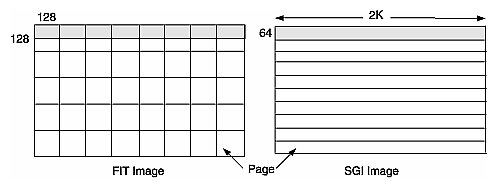
For example, suppose that you are copying an image with pages that are 128 pixels square (these are the default page dimensions for FIT images) to an image that sets the page width to match the width of the image (this is true for SGI RGB images). Further, suppose that both images are 2K pixels wide and that the SGI image sets its page height to 64 pixels. Figure 7-1 shows the two images and the pages contained in them. (This figure is not drawn to scale.)
To write a single 2 KB x 64 SGI page, you need data from all the FIT pages that span the width of the image. Thus, in this example, set the cache size to (2 KB x 64 + 2 KB x 128) x 3 bytes (assuming that there are 3 channels and that the data type is iflChar). Add about 10% to this figure to allow for the size of page descriptors and other overhead. This allows all needed pages to be held in the cache. If the cache is smaller than this, the data can still be processed, but FIT pages are bumped out of the cache and then read back in as successive SGI pages are written.
The use of multi-threading can affect the size of cache in an application (see “Multi-threading”). With multi-threading enabled, the cache can grow larger than its preset limit if all the pages contained within it are locked down and another page must be brought into the cache. This growth of cache prevents deadlock, but can cause the application to use more memory than you wish. To prevent this behavior, do one of the following:
reduce the number of threads (so that there are never more threads than pages in the cache)
reduce the size of each page (so that there are enough pages in the cache for all the threads)
increase the size of the cache (so that there is one page for each thread)
For example, if there is room in the cache for only two of the operator's pages but there are four threads, the cache may be grown so that it contains four pages. If this is unacceptable, either reduce the number of threads to two or reduce the size of a page by half (so that the cache can contain twice as many, or four, pages). Multi-threaded applications always need more memory to run efficiently; the best solution is to add more memory to your system. If this is not possible, the next best solution is to reduce the page size.
As explained in “Priority”, the pages of an image that are brought into cache as the result of an operation on the image are kept there until the cache becomes full. When the cache is full, decisions must be made about which pages are kept in cache and which are discarded and replaced by new pages.
IL attempts to optimize the use of cache. You can also affect the caching process by using the setPriority() and lockPage() methods. It is helpful, when you are optimizing your use of cache, to understand actions IL is also taking to accomplish this. IL considers these factors as it manages the contents of cache:
time since the last reference to a page. Pages most recently referenced are least likely to be overwritten.
number of references made to a page. Pages that are frequently referenced are least likely to be overwritten.
the destination of a page. IL automatically raises the priority of a page request for data that is directly displayed. This has the effect of caching data at the end of a displayed chain.
Sometimes it makes sense to cache data at points other than at the end of a chain. The reference counting used in the page replacement algorithm can help to accomplish this caching, but in cases where explicit knowledge of the application is required, you can use the setPriority() method of ilImage to set the priority of the image containing the specified page. For instance, you may want to raise the priority of the file input to a long chain to avoid rereading the input if the chain is expected to be altered.
You may also want to raise the priority of the input to an operator that is having its parameters interactively modified, although again the reference counting built into IL will tend to automatically increase the priority for you.
You can monitor image data cache usage in two ways:
by using the image tool ilMonitor. This provides an interactive means for you to monitor the use of the cache. See “Image Tools” for more information about ilMonitor.
by setting the environment variable IL_MONITOR_CACHE to a value of 1. This causes IL to print a message for each page loaded into the cache or deleted from the cache. The message identifies the page location in its associated image and the class and address of that image.
It is often important to know about the operator images (such as color converters) that are automatically inserted by IL. You can use ilDumpChain() to print out a simple description of an IL chain.
An example using this environment variable is shown below:
% setenv IL_MONITOR_CACHE 1 % imgview /usr/demos/data/images/weather.fit Page (0,0,0,0) loading in Color(0x10034ec8) Page (0,0,0,0) loading in FIT(0x1001d010) |
This example shows that a color converter operator image has been used to cache the data from the FIT image in frame-buffer format. It also shows the background view with ilConstantImg as input that is automatically created by ilDisplay. You can use this technique to identify cache thrashing if you suspect it is occurring. You can eliminate such problems by one of the techniques described in the preceding sections.
For more challenging situations, you may want to use the setPagingCallback() method in ilCacheImg. Refer to the ilCacheImg reference page for more details.
| Note: Do not attempt to use setPagingCallback() and ilMonitor at the same time since ilMonitor uses the setPagingCallback() mechanism. |
Image data is always cached in pages. A file image's page dimensions match those used to store the image on disk. By default, an operator's page size is defined by its input images. Certain operators override this default size, which can affect the caching of images. Some images also let you set the size of the pages in the cache and the data type and ordering of the cached data. The data type and ordering affect how data is cached, so if you change these attributes, you might also want to change the size of the cache.
Operators (ilOpImg objects) can set minimum pages sizes to increase efficiency. ilSpatialImg, for example, sets the minimum page size to a multiple of the kernel size.
Operators are usually the only images that allow you to set the page size. The ideal page size depends on the particular application, but in general you want an image's page size to be as close as possible to that of whichever image it is being copied to or read from. If the application involves roaming on a large image, however, the page size should be relatively square. The functions that change page size are defined by ilImage and are explained in “Page Size”.
Large pages use up more memory, which is a problem when the cache grows beyond its limit and starts allocating extra pages to get around deadlock. See the previous section for suggested solutions. Making pages too small, however, forces too much processing overhead. A page should not be smaller than 32 x 32 pixels, and in general the total number of bytes in a page should be between 16KB and 64KB. This range typically works out to be 128 x 128 to 256 x 256 when measured in pixels. Some operators, such as the frequency domain ones, are more efficient when the page size is a power of 2.
The copyTile() method is an efficient way to copy a tile of data from one ilImage to another:
ilStatus copyTile(int x, int y, int nx, int ny,
               ilImage* other, int ox, int oy,
               int* chanList=NULL);
|
By default, the tile is copied to the calling image from the image pointed to by other. The x and y arguments specify the origin of the tile in the destination image, and nx and ny specify the size of the tile. The tile that is to be copied is located at (ox,oy) in the other image. (If the tile is at the same location in both the source and destination images, then x=ox and y=oy.) If the source and destination images have different orientations, the data is transformed automatically as necessary.
You may sometimes need a temporary buffer to work on image data. Using copyTile() instead of getTile() or setTile() to transfer data between images eliminates the need for temporary buffers, saving you memory. copyTile() is explained in “Accessing Image Data”.
In addition to temporary buffers you may allocate to hold data, IL allocates buffers to operate on data internally. The amount of buffer space that IL can allocate at any one time depends on the number of threads running concurrently. If three threads are performing image processing operations on three tiles, in general, three buffers of the necessary sizes must be used. However, extra buffer space is not used if the operator in question is locking down pages, transferring data from input cache to output cache, and operating on the data “in-place.” Certain operators derived from ilMonadicImg do this. If you derive a new operator from ilMonadicImg or any of its descendants, you might want to ensure that your derived class operates on its data in-place by setting its inPlace member variable in the constructor.
IL can accelerate some image processing sequences on SGI computers that result in a displayed image (as opposed to sequences that result in a file). This section describes which IL operations can be accelerated, the constraints on these operations, and the underlying graphics resource required for these operations.
This section describes the operators that can be accelerated for display and the related OpenGL functions that are required to accomplish the operators.
These operators use the OpenGL blend facility to arithmetically combine two or more input images. The primary (zero-th) input is rendered first to the frame buffer. Then the subsequent inputs are rendered to the same location with the appropriate OpenGL blend function enabled to accomplish the operation.
ilMultiplyImg can only be accelerated if both input min values are zero.
ilSubtractImg is accomplished by negating the secondary input. Only constant-alpha-type blending can be accelerated.
In some cases, the operation cannot be accelerated if the input data ranges differ.
These operators use the OpenGL logic OP facility to logically combine two or more images. They use multi-stage rendering operations similar to that of ilBlendImg. ilInvertImg, however, is done in a single rendering operation.
Convolution operators use the OpenGL 2D convolution extension. To facilitate acceleration, the kernel data must
be of type float
be of one of the following sizes: 3x3, 5x5, 7x7
have the origin in the center of the kernel
IL uses the OpenGL color matrix. The matrix size must be less than or equal to 4x4. The bias must be zero. Some matrices with negative weights may not be accelerated because they cannot be scaled correctly.
IL uses OpenGL color tables. OpenGL provides four color tables (see Table 3-3). The color table that is used for a particular operator depends on the LUT input (see Composition). LUTs can be up to 4K long.
IL uses OpenGL pixel scale, bias, and clamping facilities. These facilities are also used to normalize input data ranges to the intrinsic zero to one ranges and to compensate for convolution kernel and colormetric affects on the operator value ranges.
IL uses OpenGL texture rendering. There are two cases, depending on the type of warp, associated with operators:
affine or perspective warp
any other type of warp
The first case sets the modelview matrix to perform the desired warp. The second case represents the warp with a regular triangular mesh. For certain simple zooms, for example, affine and perspective warp, the OpenGL pixel zoom facility is used instead of texture.
The texture required for other warp cases is associated with the input of the warp operator. Thus, multiple warp operators that share input also share the same texture. See for more information about IL's use of texture.
IL uses OpenGL's histogram and minmax facility. The number of histogram bins must be less than or equal to 4096. The input data order must be interleaved. An ImgStat with a rectangular ROI can be accelerated, but one with any other kind of ROI cannot.
| Note: ilHistLutImg and ilHistScaleImg use ilImgStat. Therefore, they accelerate statistics-gathering and the rendering parts of the operations. |
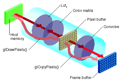
The OpenGL Imaging Extension (OIE) specifies a sequence of image processing operations that can be enabled during a pixel transfer operation. A pixel-transfer operation can be one of the following:
an image is drawn from the host memory to the frame buffer
an image is copied from one frame buffer to another
an image is loaded from the host to texture
an image is copied from the frame buffer to texture
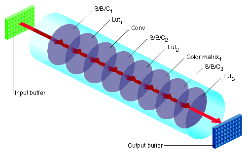
In each case, a rectangle of pixels is transferred from one buffer to another. During the transfer, any of the image processing operations shown in Figure 7-2 can be active.
In Figure 7-2, the input can be the host memory or a GL buffer, the output can be a GL buffer, texture, or host memory, and S/B/C stands for scale/bias/clamp operators. To use hardware acceleration, the operators must follow the order in Figure 7-2. Not all of the operators need to be enabled. What is not allowed, for example, is Lut1 to precede S/B/C1. If you need to use operators out of order, you need to use pixel buffers, as described in “Pixel Buffers and Multi-Pass Acceleration”.
Most of the accelerated IL operators use one or more elements in the Image Processing pipeline.
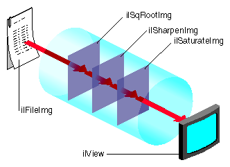
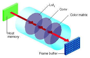
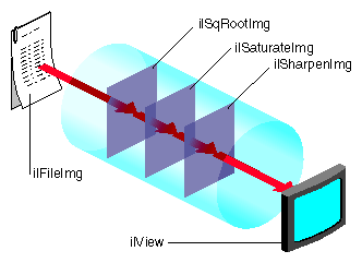
Since the OGLIP supports a sequence of operations in a single operation, it is possible to compose several IL operators for acceleration, provided they occur in the right order, for example, IL chain shown in Figure 7-3 can be displayed by copying the file image cache directly to the frame buffer while enabling the subsection of the OGLIP pipeline shown in Figure 7-4.
Figure 7-4 shows that all three operators are accelerated. ilSqRootImg, ilSharpenImg, and ilSaturateImg correspond to Lut1, Conv, and Color Matrix, respectively.
However, if the chain is reordered, as shown in Figure 7-5, so that the sharpen occurs after the FalseColor, the sequence cannot be fully accelerated because it does not match the sequence of operators in the OGLIP pipeline. When a sequence cannot be wholly mapped to the OGLIP, IL selects the longest subsequence to run as a single operator.
Given the IL chain shown in Figure 7-5, only the sharpen operator would be accelerated with a single-pixel transfer. The other two operators would be evaluated in the normal, unaccelerated manner.
The next section describes how chains as shown in Figure 7-5 can be fully accelerated through the use of pixel buffers.
OpenGL provides non-volatile, off-screen framebuffer memory, called pixel buffers, for storing intermediate results. This feature enables IL to fully accelerate chains that do not completely map onto the OGLIP as a single transfer operation. For example, the IL chain, shown in Figure 7-6, is accelerated with the two-pass sequence of transfer operations.
Pixel buffers are, in general, eight to twelve bits per component. The exact depth of the pixel buffers can be determined by examining the attributes of the glx visual associated with the pixel buffer. The command
% glxinfo -fbcinfo |
prints a summary of the available visuals. The limited depth of the pixel buffers limits the precision of the stored image data.
Pixel buffers are allocated by IL in units of the display size. The total number of allocated pixel buffers can be limited either programmatically through calls to ilSetNumPBuffers() and ilGetNumPBuffers(), or through the environment variable IL_NUM_PBUFFERS.
IL employs the OpenGL texture facility to accelerate warp operators. From the standpoint of hardware accelerators, a texture is an intermediate storage buffer similar to a pixel buffer. However, the size of the texture is usually smaller and the component depth is shallower. The component depth is dependent on the resampling mode for the warp (for example, ilNearNb, ilBiLinear, and ilBiCubic) and the color model.
A texture is associated with the input of a warp. If several warp operators share the same input, they also share the same texture. The texture cache is unaffected if the warp is interactively altered to enable fast, interactive displays of changing warps.
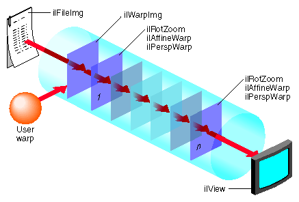
IL provides limited support for displaying a combination of warps in a single rendering pass. Specifically, you can string together any number of perspective (ilPerspWarp) and affine (ilAffineWarp) warps into a single step. This combination of warps is called a transform matrix. Figure 7-7 shows an IL chain of operators.
Figure 7-8 shows the underlying data path of the IL chain in Figure 7-7.
Figure 7-8. Data Path of the IL Chain in Figure 7-7
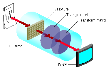 |
Figure 7-8 shows that IL associates a texture with the ilFileImg object and derives a triangular mesh from the user-defined warp. All of the perspective warps, affines, and rotzooms are combined into the transform matrix. When any of these warp values change the images change accordingly, however, changing the transform matrix does not change the cached values for the texture and the triangular mesh. By preserving these cached values, the use of the transform matrix accelerates image processing.
When the input image is larger than the texture, the data must be paged into texture according to what is currently being viewed. When the texture requirement for a particular rendering operation greatly exceeds the texture capacity, performance degrades. In this situation, rendering is limited by the rate that texture can be loaded into the cache rather than by the rate that it can be rendered.
The triangular mesh associated with a general warp is also paged into memory so that only the displayed portion of the warp is evaluated. The results are cached and reused in subsequent rendering operations.
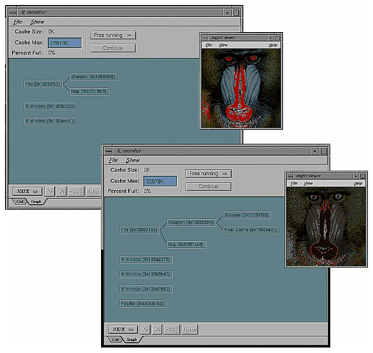
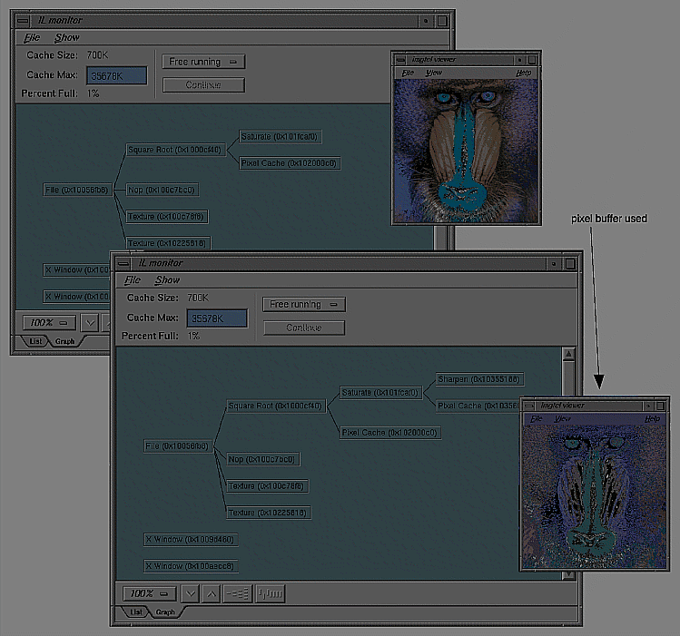
The difference between the pipelines in Figure 7-3 and Figure 7-5 is that Figure 7-5 uses a pixel buffer as an intermediary to create the final image. By turning on the monitor, you can view the use of the pixel buffer in each pipeline by using the imgtcl program, which is included in the software distribution. To view the results of Figure 7-3 at each stage of the pipeline, use the following commands:
% setenv IL_MONITOR 2 % imgtcl imgtcl> ilfileimgopen monkey /images/monkey.rgb monkey imgtcl> view monkey imgtcl> ilSqRootImg sqroot monkey sqroot imgtcl> view sqroot imgtcl> ilSharpenImg sharp sqroot sharp imgtcl> view sharp imgtcl> ilSaturateImg sat sharp sat imgtcl> view sat |
To view the results of the pipeline in Figure 7-5, reverse the ilSharpenImg and ilSaturateImg commands, as follows:
% setenv IL_MONITOR 2 % imgtcl imgtcl> ilfileimgopen monkey /images/monkey.rgb monkey imgtcl> view monkey imgtcl> ilSqRootImg sqroot monkey sqroot imgtcl> view sqroot imgtcl> ilSaturateImg sat sqroot sat imgtcl> view sat imgtcl> ilSharpenImg sharp sat sharp imgtcl> view sharp |
Because the first two operators are the same in the pipelines shown in Figure 7-3 and Figure 7-5 their images and monitor displays are identical. Figure 7-9 and Figure 7-10, however, show the differences in the images and monitor displays caused by reversing the ilSaturateImg and ilSharpenImg operators.
Qualitatively, you can see that changing the order of the operators introduces added complexity in the monitor displays shown in Figure 7-10. More specifically, you can see that the ilSharpenImg operator in Figure 7-10 introduces the use of a pixel buffer.
The total number of bytes of texture is configurable. The installed amount is encoded in the OpenGL renderer string. For more information, see the man page for glGetString.
Texture is divided into two logical banks. Bilinear and nearest neighbor textures are allocated within a single bank. Therefore, the maximum texture size for bilinear and nearest neighbor texture is half the installed amount. Bicubic texture allocation is split across the two banks. Therefore the maximum size of a bicubic texture is the same as the installed amount.
Whenever a warp image is accelerated with texture, an auxiliary texture is managed that shadows the input to the warp image. The size of this texture must be a power of two. If the image is larger than the maximum allocatable texture size, then the maximum size texture is used and maintained as a wrap-around image cache.
This section describes the limitations and operating parameters for hardware acceleration on different platforms.
The following restrictions apply to all platforms:
The default pbuffer depth is based on the available X Visuals on the system. The depth is determined by selecting the greatest-order visual class, usually TrueColor, that has at least 8 bits per component, and includes alpha planes. It is not possible to copy from a pbuffer to a window (or another pbuffer) with a different visual class.
Convolution kernel sizes must be 3x3, 5x5, 7x7, separable or general, and of type float. The edge mode must be ilPadSrc, ilPadDst, or ilNoPad.
The color matrix (for ilFalseColorImg and ilSaturateImg acceleration) has. at most, 4 x 4 entries. The bias vector for ilFalseColorImg must be all zeros and the matrix should have equal gain for each output channel, that is, the sum of the positive elements and the sum of the negative elements should be the same for each matrix row.
The look-up table size must be limited to 4096 entries.
The histogram size must be limited to 4096 entries.
Multiply is accelerated only if the minimum scale value of the input images is zero.
Add is not accelerated for images with greater than two inputs.
Statistics are accelerated only for interleaved data.
The amount of texture available depends on the amount of texture memory available in the system and the texture data format. An application should use ilHwConnection::getTexCapacity() to determine the amount of texture available on any given platform.
For any platform, an application should get at least one pbuffer for any framebuffer configuration unless another application has taken all of the pbuffers.
Currently, the maximum amount of texture memory is 64 MB. The number of pbuffers depends on the number of installed Raster Manager (RM) boards and the depth (in bits) of the pbuffer. At the default depth, 12 bits, a 1 RM system can allocate 2 pbuffers.
The maximum texture lookup table size is 4096 entries if the texture and lookup table format is single component, 2048 if neither format is more than 2, 1024 otherwise. These numbers assume another application has not already taken the pbuffers.
Restrictions for the Reality Engine are the same as for the InfiniteReality, except for the following conditions:
The maximum amount of texture memory is 16 MB.
The OpenGL imaging pipe is restricted. It contains none of the extended lookup tables, except for the texture lookup table.
Color matrix cannot be concatenated onto a convolution.
No pixel transformations in the imaging pipe can be active when loading texture. The same is true for statistics operations.
The maximum texture lookup table size is 256.
Textures (and display lists) cannot be shared across GLX contexts.
InfiniteReality does not support bicubic texture resampling.
Cannot accelerate conversions from color palette data to RGB.
Cannot load texture from pbuffer safely. (The data cannot be swapped and may be obliterated due to a contending process.) It is disabled by default. It can be enabled by setting the hint, IL_TEXTURE_FROM_PBUFFER_OK_HINT.
Restrictions for the Impact are the same as for the InfiniteReality, except for the following conditions:
Max Impact has 1 MB of texture memory, High Impact has 1 MB of texture memory, and Certain Impact has no texture memory.
The maximum texture lookup table size is 256.
Impact does not support bicubic texture resampling.
Impact cannot convolve if the input is float type.
Impact cannot convolve into texture.
Some framebuffer configurations of High Impact do not support pbuffers.
The ilHwHint class provides a mechanism for setting hardware-specific attribute values. You can use this mechanism with the hints provided in the ImageVision library or you can create hints of your own.
You can set hints globally or on operators. Hints set on operators take precedence over globally-set hints.
An example of a hint is IL_TEXTURE_FORCE_HINT, which is defined in IL. This hint is used on warp objects to force the warp operator to use texture even when a pixel zoom could be used.
Because ilHwHint::setHwIntHint() is overloaded, you can set a hint using either a hint name or ID. Using a hint name causes a hit in performance because it requires a lookup of the hint name. It is more convenient, however, to set a hint using its name. If you set a hint repeatedly, use the hint ID to set it. If you set a hint only once, use the hint name to set it.
Because hint IDs are set at runtime, your application must first lookup a hint ID, save the ID so that it does not have to be looked up again, and set the hint using the hint ID. Example 7-1 shows this procedure.
int texSizeIntHintID; // Find and save the hint ID using its name. texSizeIntHintID = ilHwFindHintID(“IL_TEXTURE_SIZE_HINT”); // Create a RotZoom object to rotate the image by 30 degrees ilRotZoomIMg rz(input, 30, 1, 1, BiLinear); // Set the hint on the RotZoom object to limit the texture size // to 1 million texels. input->ilImage::setHwIntHint(texSizeHintID, 1024*1024); |
Instead of going through the trouble of finding the runtime hint ID and then setting the hint based on it, you can just set the hint using the hint name, as follows:
input->setHwIntHint(IL_TEXTURE_SIZE_HINT, 1024*1024); |
The trade-off for this easier construction is slower performance.
Table 7-1 describes the ilHwHint values currently recognized by IL.
Table 7-1. ilHwHint Definitions
Name | Description |
|---|---|
IL_TEXTURE_SIZE_HINT | Uses int-valued hint to control the size in texels of a warp operator input texture. |
IL_TEXTURE_COMPONENT_SIZE_HINT | Uses int-valued component size hint to control the warp operator input texture. |
IL_TEXTURE_MESH_STEP_HINT | Uses int-valued hint to control the warp mesh step size. |
IL_TEXTURE_MESH_PAGE_X_HINT IL_TEXTURE_MESH_PAGE_Y_HINT | Controls warp mesh page size (should be a power of two). |
IL_PIXEL_BUFFER_WIDTH_HINT IL_PIXEL_BUFFER_HEIGHT_HINT | Uses int-valued hints to control pixel buffer dimensions. |
IL_TEXTURE_FROM_PBUFFER_OK_HINT | Uses int-valued hint to enable sourcing texture from pixel buffer on RE (off by default because correct texture swapping is not guaranteed). |
IL_TEXTURE_LIMIT_HINT | Uses int-valued limit in bytes to control global texture allocation for an application. |
IL_TEXTURE_FORCE_HINT | Makes a warp object use texture, even if it could use pixel zoom. |
IL_FORCE_PASS_HINT | Disables composing with input pass; effectively creates a multipass operation with pixel buffer cache between them. |
IL_ROAM_VIEW_HINT | Chains a texture onto an image when displayed in an ilView; allows for fast roaming over an image. |
IL_HW_HINT_ALERT_PROP_NAME | Marks an ilLink-derived object as altered when a parent's hints are changed or when the global hints are changed. |
If you are implementing your own hardware acceleration, you may need to create your own hints to control it. The ilHwHint class pairs a name with a value. You use these values to optimize the performance of your application. The base class provides the means to set and get the name in the following methods:
ilHwHint(const char* hintName); const char* getHintName(); ilHwHint(int hintID); ilHwFindHintID(const char* hintName) |
The base class does not. however, provide methods to set or maintain values associated with hint objects; that job is left for ilHwHint-derived classes. For example, you could provide access to some integer value associated with a derived hint-class object, ilHwIntHint, as follows:
class ilHwIntHint : public ilHwHint {
public:
    ilHwIntHint(int hintVal) : ilHwHint(“ilHwIntHint”)
        { val = hintVal; }

private:
    int val;
};
|
| Note: You can use the base class directly only if the hint object does not need to define an explicit value. In some cases, the presence of a hint on a hint list is sufficient. |
When you create a hint object, it is assigned an ID. The first object has an ID of zero and the following objects have ID numbers of 1, 2, 3, and so on. You can retrieve the ID of a hint using the following ilHwHint method:
int getHintID() |
You can use hint IDs to accelerate hint lookups in a list of hints. To look up a name, use the name of the hint or its ID, if the derived class caches it. Hint lists are described further in “Hint Lists”.
ilHwHintList manages a hint list, which is an array of hints. Using hint lists can dramatically improve performance by reducing lookup delays.
To add a hint to a hint list, use one of the following methods:
ilStatus setHint(ilHwHint* hint, int adopt = FALSE); ilStatus setIntHint(int hintID, int val); ilStatus setIntHint(const char* hintName, int val); |
To return the hint specified by a name or ID, use one of the following methods:
const ilHwHint* getHint(int hintID) const; const ilHwHint* getHint(const char* hintName) const int getIntHint(int hintID, int& val) const; int getIntHint(const char* hintName, int& val) const; |
To remove a hint, specified by a name or ID, from a hint list, use one of the following methods:
ilStatus removeHint(int hintID); ilStatus removeHint(const char* hintName) ilStatus removeHint(ilHwHint* hint) |
