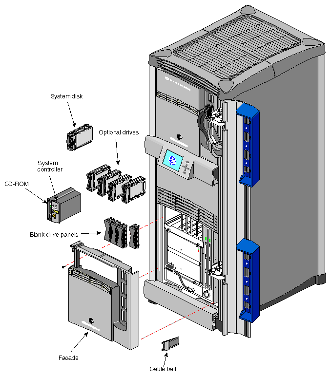
This chapter describes the installation and removal procedures for customer-replaceable units (CRUs) in the Origin2000 rackmount system. The CRUs are hardware components that can be safely removed by an end user without undue exposure to high electrical power potentials. CRUs are limited to the following major components (see Figure 6-1):
drive modules
module System Controller (MSC)
| Warning: Do not attempt to remove or replace hardware components (such as boards) that are not listed above. This system uses internal electrical power that is hazardous if the equipment is improperly disassembled. Failure to heed this warning may not only void the system warranty but could cause personal injury. |
Read the following subsections for additional safety information and required tools.
Before beginning the replacement procedures, observe these precautions.
| Warning: This equipment uses electrical power internally that is hazardous if the equipment is improperly disassembled. Board removal and replacement should be performed only by Silicon Graphics-certified personnel. |
| Caution: Do not attempt to move CrayLink Interconnect cables. These cables are made of sensitive copper strands and insulation material that can be damaged if they are excessively bent, stretched, or stepped on. |
This equipment is extremely sensitive and susceptible to damage by electrostatic discharge (ESD) which is caused by the buildup of electrical static potential on clothing and other materials. Use proper ESD preventive measures and observe these precautions:
Wear a properly grounded wrist strap when connecting and disconnecting peripherals.
Be sure that you and all the electrical equipment you handle are at ground potential to avoid damage from ESD. Do not rely on the power source ground; the ground is lost when the system is disconnected from the power source.
Keep boards in their antistatic bags until you are properly grounded to the chassis ground with a ground strap.
Do not use an ohmmeter or a digital voltmeter on a board.
This section describes related activities that are common to most CRU installation and removal procedures for the Origin2000 rackmount chassis.
You can either power off an individual module or power off the entire rack configuration using the multimodule System Controller (MMSC). If you power off an individual module, the other module(s) in the configuration can still operate fully.
Use these procedures to power off a module in a rack:
Ensure and verify that the desired file systems are backed up and make sure that all users are off the target system.
Become superuser, then shut down the system software as follows:
# shutdown -y g0
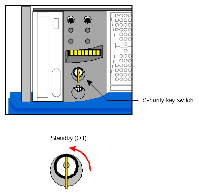
Turn the module controller key switch to the Standby position (see Figure 6-2).

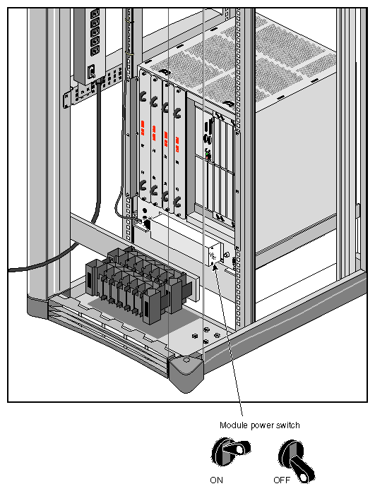
Caution: The “Standby” mode does not turn power completely off to the module. Voltage is still present in the system. Power off the module. The switch is located in the rear of the chassis, near the AC power cord receptacle (see Figure 6-3). Disconnect the system from the power source.
Use these procedures to power off a single-rack system.
Power off the individual system modules, see “Powering Off an Individual Module System”.
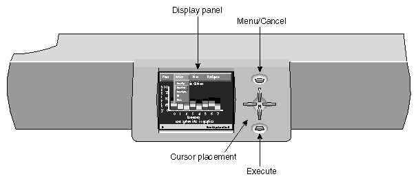
Power off the MMSC display (see Chapter 7, “Using the System Controller” for additional information).
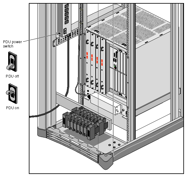
Turn off power to the power distribution unit (PDU), see Figure 6-5.
See Chapter 7, “Using the System Controller” then use these procedures to completely power down an entire multi-rack configuration.
Power down the individual system modules (see “Powering Off an Individual Module System”).
Power off the individual racks. It is recommended that you start from the rightmost rack and then continue with the rack to the left. This helps ensure a cleaner and more efficient shutdown process.
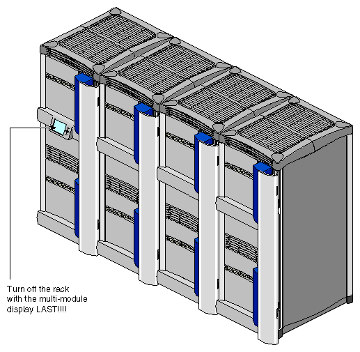
Turn off the rack with the MMSC last (see Figure 6-6).
Turn off the PDU on the last rack (see Figure 6-5).
Use these procedures to open the drive door on a rackmount system:
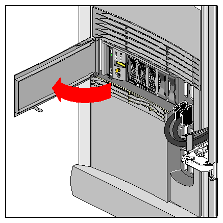
Swing open the drive door as shown in Figure 6-7. When closing the door, push it all the way in to engage the plastic tab on the bottom of the door.

Note: The door should normally be in the closed position to help keep out dust and other possible contaminants from the drives and MSC.
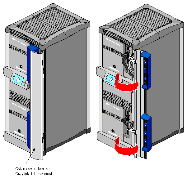
The cable cover door (see Figure 6-8) provides aesthetic shielding for the CrayLink Interconnect cabling on the rackmount chassis and between side-by-side rackmount systems.
The following section provides instructions for replacing the customer-replaceable units (CRUs). To replace a CRU, use Figure 6-1 to identify the appropriate unit and its position in the chassis. Then proceed to the appropriate section and perform the steps.
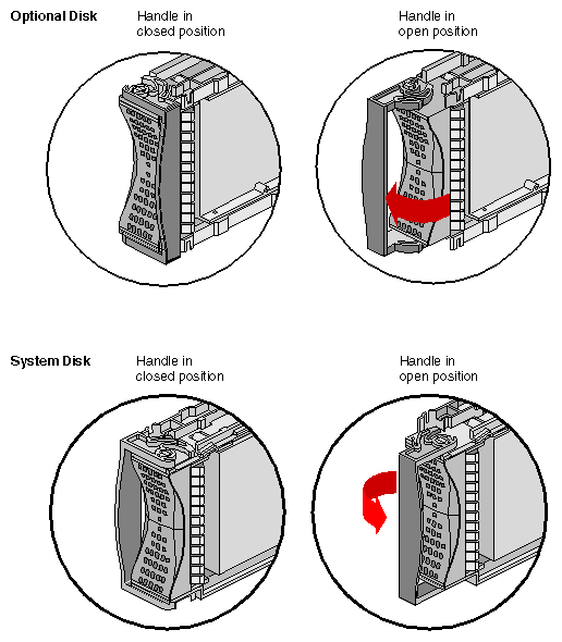
Disk drive modules are aligned vertically at the front of the chassis. Note that the leftmost disk drive—the system drive—is oriented differently from the others as shown in Figure 6-9.
Ensure that the system is powered off and unplugged.
To remove a disk drive module, snap the handle to the right or left (depending on the drive orientation) to the open position. The handle is centered, as shown in Figure 6-9.
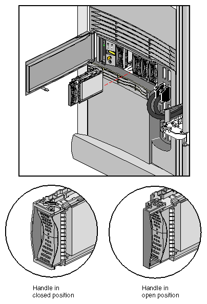
Pull the disk straight out (see Figure 6-10).
To insert a disk module, follow these steps:
Ensure that the system is powered off and unplugged.
If necessary, snap the handle to the open position so that it is centered, as shown in Figure 6-10.
If you are adding a drive, remove the drive filler plate that covers the drive slot you want to use.
Align the new disk module with the drive guide, as shown in Figure 6-9.
Gently but firmly slide the disk module on the guides over the pin. When the disk module is all the way in, it snaps.
When the disk module is in all the way, snap the handle right to the closed position, as shown in Figure 6-10. In the case of the system disk module, which is upside down relative to the other drives, snap the handle left.
Use the packaging for the new disk module to repackage the old disk module.
The facade must be taken off before you can remove the System Controller and CD-ROM assembly. Use these procedures to remove the facade:
Lift off the cable bales that hold the CrayLink and Xpress link cables in place.
Remove the CrayLink Interconnect and Xpress link cables from the Rack Router board ports (as required).

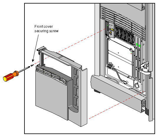
Caution: Be sure that the connectors are labeled before you remove them, so that you know where to replug them afterwards. Remove the screw that secure the facade to the chassis (see Figure 6-11).
Lift up to disengage the facade from the chassis; then pull it straight out.
Reverse these steps to install the facade.
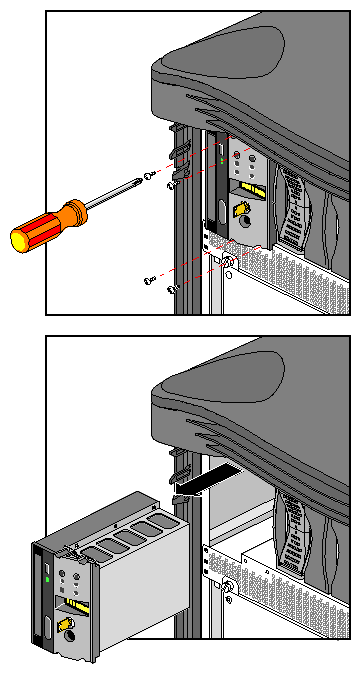
The System Controller and CD-ROM drive are packaged together in one assembly. To replace either component, you must remove and insert an entire new assembly.
| Caution: Do not attempt to remove the MMSC and display. This procedure should only be performed by Silicon Graphics-certified personnel. |
Power off the system (see “Powering Off a Rackmount System”).
Remove the facade (see “Removing the Facade”).
Remove and reserve the screws that hold the assembly in place, as shown in Figure 6-12.
Insert the new assembly, using the reserved screws.
Repackage the old assembly.
Each Origin2000 system comes with 12 XIO board slots. Various types of optional interface boards are supported in the XIO slots. These may include
peripheral component interface (PCI)
high-performance parallel interface (HIPPI)
Fibre Channel
graphics interface (SI Viz Console Board Set)
There are certain installation restrictions that must be followed when XIO boards are installed or removed. Failure to follow these configuration rules may result in system or peripheral malfunction.
Always
Keep the BaseIO (IO6S or IO6G) board installed in XIO slot 1
Fill the top XIO slots first (XIO slots 3 and 5 should be filled first)
Have the PCI module installed in XIO slot 2
Have the SI Viz Console installed in XIO slots 3 - 12
Never
Move the BaseIO (IO6S or IO6G) board to a slot other than XIO 1
Have a SCSI board installed in XIO slot 2
Have an XIO board installed in an unsupported slot (see “Board Configuration and Layout”)
Have more than one Si Viz Console board installed in one Origin2000 system
