This chapter describes how to use the two system controller types in a rackmount system.
multimodule System Controller (MMSC) and display
module System Controller (MSC) and display
The MMSC in a rackmount system is an intelligent communcations device that can monitor one or more system “modules” within a rack.
The MSC in a deskside system or a rackmounted system “module” is less sophisticated than the MMSC. Each MSC in a rack reports to and can be controlled by the MMSC.
The MMSC subsystem is composed of two main components:
the MMSC itself
the front display and input panel
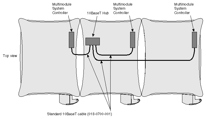
10BaseT Ethernet hub (only in systems with three or more racks)
The MMSC's front display and input panel interface is only necessary in the primary rack of a fabric-interconnected multiple-rack system.
A MMSC must be installed in each rack in a fabric-interconnected multiple-rack system.
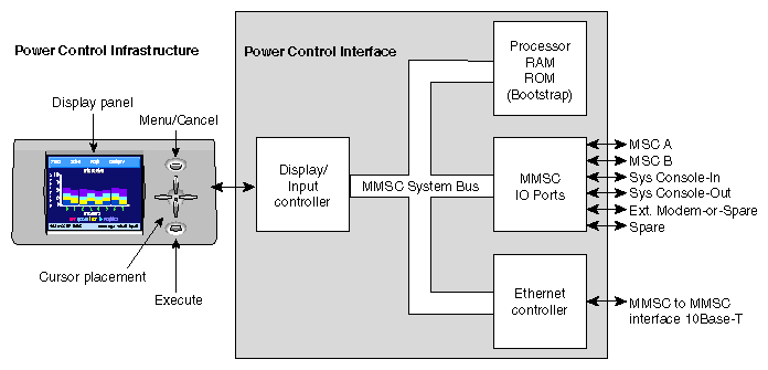
Figure 7-1 shows a functional block diagram of the MMSC.
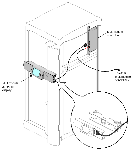
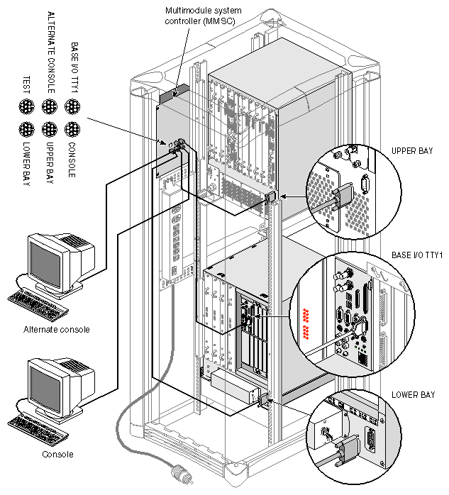
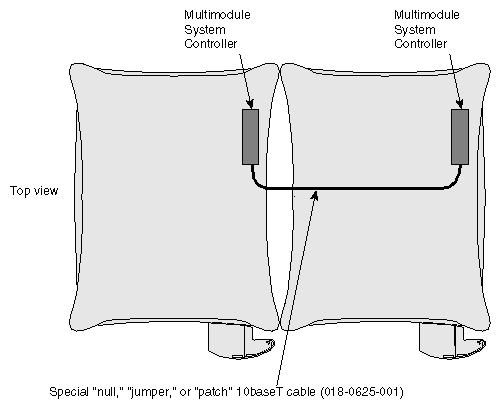
The MMSC assembly in each rack interfaces with the local MSC RS-232 interface on each system installed in that rack (see Figure 7-2). The “satellite” processor assembly(s) interfaces to the master MMSC (with the front panel display). The processor assemblies in multirack configurations communicate directly via a 10BaseT Ethernet connection. This scheme provides access to every MMSC and MSC in a fabric-interconnected multirack system.
Note that the MMSC Ethernet is a closed Ethernet system used by the MMSCs only.
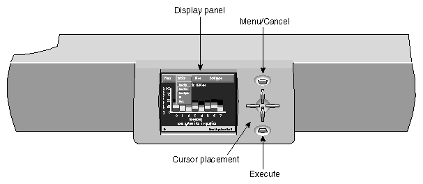
The front display and input panel mounts on a cross section piece above the lower front air intake baffle (see Figure 7-3). The front display panel's color TFT (thin film transisitor) screen measures approximately 4 inches high and 5-1/2 inches wide (10.2 cm x 14 cm).
The panel's input device consists of six push button switches:
one to control menu selection
one to execute selections
four to position the cursor (up, down, right, and left)
With these buttons you can navigate and execute menu options listed on the display. Communication between multiple fabric-linked rack systems is accomplished with a 10BaseT Ethernet connection. This allows you to communicate with and control system modules (via their MSC) in other racks from a single location.
| Caution: The front panel display provides a convenient method to power on, shutdown, reset, and to issue a nonmaskable interrupt (NMI) to the entire rack configuration. Use extreme care when issuing these commands from the display. Make sure that all affected users are notified before a system-wide command is executed. |
Follow these instructions to power on an entire rack configuration through the MMSC display.
Select the “Focus” menu on the display using the direction keys, then press the Enter key.
Make sure that the “Al” option is highlighted
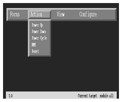
Go to the “Action” menu on the display using the direction keys (see Figure 7-4).
Select the “Power Up” option and press the Enter key.
Follow these instructions to reset an entire rack configuration through the MMSC display.
Select the “Focus” menu on the display using the direction keys, then press the Enter key.
Make sure that the “All” option is highlighted
Go to the “Action” menu on the display using the direction keys (see Figure 7-4).
Select the “Reset” option and press the Enter key.
Follow these instructions to power down an entire rack configuration through the MMSC display.
Select the “Focus” menu on the display using the direction keys, then press the Enter key.
Make sure that the “All” option is highlighted
Go to the “Action” menu on the display using the direction keys (see Figure 7-4).
Select the “Power Down” option and press the Enter key.
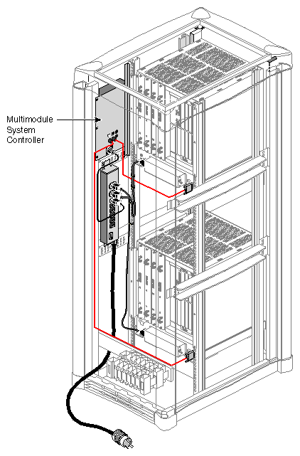
The MMSC mounts internally in the rack without removing any boards in the system. Figure 7-5, Figure 7-6, and Figure 7-7 show MMSC cabling configuration examples. Figure 7-8 shows the location of the MMSC in relation to other components in the rack system. The processor assembly can interconnect directly to:
the RS-232 System Controller interface on the back of each system module installed in the rack
the front display and input panel
additional MMSCs in adjacent racks via 10BaseT Ethernet
The MMSC interfaces listed above are augmented by system console in-and-out RS-232 connectors and a modem connector. Note that when the MMSC is connected to the RS-232 interface on a system mounted in the rack, you may not use the eight-pin DIN connector on the front of a system module's MSC.
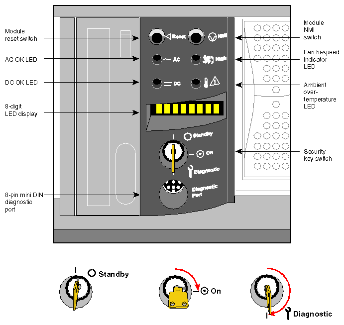
The MSC front panel is shown in Figure 7-9.
The MSC provides environmental monitoring for safe operation of the deskside system. The MSC connects to the system midplane via a transition or “bridge” board and provides easy user access to switches and displays at the front of the deskside system.
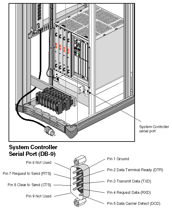
In the lower right section on the back of the deskside system is a DB-9 alternate console diagnostic port serial connector that is a direct mirror of the 8-pin diagnostic connector on the front panel. Figure 7-10 shows the location and pinouts of the 9-pin rear-mounted MSC diagnostic connector.
The System Controller has one keyswitch, two push buttons, and four LED indicators. The following paragraphs provide information on the use or significance of each control or indicator.
The Front Panel Keyswitch selects Standby, On, or Diagnostic status for the system.
The System Reset push button initiates a system-wide reset of the deskside. The keyswitch must be in the diagnostic position to use this button.
The Non-Maskable Interrupt (NMI) switch issues a reset signal to all Node boards in the system. The keyswitch must be in the diagnostic position to use this button.
The AC Power OK green LED lights when the system is plugged into an outlet and the AC circuit breaker is turned on. The Controller is receiving DC voltage (V_5 Aux) through the midplane, as are other boards that require it.
The DC Power OK green LED lights three and one-half seconds after the keyswitch is turned to the On position. This indicates the system power supply is enabled and operating properly.
The Fan Speed High amber warning LED lights when the fans are running at high speed, which may be an indication that ambient temperature is higher than optimal or a non-critical fan has failed. When a non-critical fan fails, the remaining fans are set at full speed to compensate. In this case, a service call should be placed immediately.
The Over Temperature Fault amber warning LED lights when the controller's incoming air temperature or fan failure detection causes a shutdown of the system. If the environmental temperature exceeds the system's tolerance, or if a critical fan fails, the controller shuts down the system. In some cases, a service call should be placed immediately. See the section “MSC Shutdown” in Chapter 8 for tips on how to troubleshoot this problem area.
The MSC has the following basic features and functions:
Issues a reset signal at power-on.
A front panel-mounted keyswitch provides a soft power-off to standby condition.
A front panel-mounted push-button non-maskable interrupt (NMI) switch.
Monitors ambient incoming air temperature into the system and adjusts fan speed accordingly (two speeds). A soft power-off of the system results when ambient temperature becomes too high for safe operation.
LED display of ambient over-temperature conditions.
NVRAM for storing configuration information (1024 x 8 bits).
Monitors fan rotation and automatically increases to high speed fan operation when a fan fails. Signals an impending shutdown when a single critical fan fails, or two or more non-critical fans fail.
LED display of high fan speed and possible fan tray failure (fan high-speed LED).
LED display of power supply operation. AC OK LED indicates AC voltage applied to system. DC OK indicates all power supply DC voltages (+12 V, +5 V, +3.45 V), and remote DC voltages (3.3 V, 2.4 V, 1.6 V) are present with no error conditions in the system. The DC OK LED does not indicate regulation or accuracy of the DC voltages present.
Provides a 100-Kbps bidirectional communication path between the MSC, mid-plane, and Hub ASIC IO space on each Node board in the system. This communication path allows the MSC to receive system status messages from all Node boards in a system, and to provide status messages from the MSC and all Node boards in a system. This communication path is referred to as the I2C interface.
Provides ability to request the system serial number and configuration information via the I2C Interface.
Eight-digit alphanumeric status display. This display is updated by the System Controller or the Node cards in the system via the I2C interface.
Provides a seven-wire 9600 bps alternate console diagnostic port for off-line configuration and troubleshooting. Also communicates with the Node board(s) when the IO console port or a system console is not available or functional. This interface also supports the minimum requirements for modem support.
Software Reset, NMI, and soft power-off commands through the alternate console diagnostic port.
Supports alternate console diagnostic port command line power supply voltage margining. Margining allows the 3.45-V or 5-V outputs of the power supply to be moved 5% higher or lower independently. This does not effect remote regulated termination voltages (1.6 V, 2.4 V, router 3.3 V).
Supports alternate console diagnostic port command-line regulated termination voltage margining for the termination voltages 1.6 V, 2.4 V, and 3.3 V, (all termination voltages will be margined 5% higher or lower together, not independently). This does not affect the power supply voltages.
Sends early warning high priority interrupt (Panic Interrupt) to all Node boards warning of impending shutdown due to AC power fail, ambient over-temperature or the switch being placed in the standby position.
Provides an interlock (removable keyswitch) to prevent unauthorized personnel from turning the system to on or standby, and to limit operation of the System Reset and NMI functions. The software password allows access and permissions through the alternate diagnostic console port.
The MSC front panel has an eight-character LED readout that supplies information about system status. Table 7-1 gives a list of MSC messages and an explanation of what the impacts may be.
Table 7-1. System Controller Messages
Message | Meaning of Message |
|---|---|
SYS OK | The system is operating normally. |
R PWR UP | The system is being powered on remotely via the MSC serial connection. |
POWER UP | The system is being powered on from the front panel switch. |
PFW FAIL | The power supplied to the system has failed or dropped below acceptable parameters. The system has shut down. |
PS OT FL | The system's power supply temperature has exceeded safety limits and the system has shut down. |
PS FAIL | The internal power supply has failed and the system has shut down. |
OVR TEMP | The system's temperature has exceeded acceptable limits and the system has shut down. |
KEY OFF | The MSCs switch has been turned to standby. |
RESET | The MSC's switch has been turned to the diagnostic position, and the reset has been button pushed. |
NMI | The MSC's switch has been turned to the diagnostic position, and the non-maskable interrupt (NMI) button pushed. |
M FAN FL | More than one fan has failed and the system has shut down. |
R PWR DN | The system has been powered off from a remote location. |
PWR CYCL | The system has received the command to power cycle from the console or a remote user. |
HBT TO | The system has registered a heart beat time-out. A non-maskable interrupt is generated, followed by a system reset. |
FAN FAIL | A system fan has failed. If it is fan 1, 2, or 3, the system shuts down. A service call should be placed as soon as possible. |
POK FAIL | A power OK failure occurred on an unidentified board. |
