This chapter explains how to set the video formats that the Multi-Channel Option outputs. It describes
setmon syntax
setting genlock
cursor position
Raster Memory boards and formats
video output formats
display surface dimensions
This chapter concludes with a programming example.
As an integral part of the graphics system, the Multi-Channel Option's video formats are set by the same method used to select the formats of RealityEngine graphics, namely, the setmon command.
| Note: It is recommended that you use a dumb terminal or remotely log in over the network to switch video modes between standard and multi-channel. |
To start the Multi-Channel Option, follow these steps:
| Caution: When the Multi-Channel Option is running, RealityEngine graphics does not output to the standard output display. |
After a power-off, system reset, or reboot, the system remains in multi-channel mode. To return to graphics mode, use:
setmon -x format
/usr/gfx/stopgfx
/usr/gfx/startgfx
|
| Note: Occasional screen anomalies, such as shifting to right or left (tile shift) or bands of incorrectly placed or black information, may appear after graphics initialization. In such cases, restart graphics with the /usr/gfx/stopgfx and /usr/gfx/startgfx commands. |
The optional setmon flag -g sets genlock. By default, the master video output channel on the Multi-Channel Option uses its own horizontal frequency timebase; the option genlocks the master channel to an external sync source.
Genlock provides horizontal, vertical, and frame lock to the external signal. Because only timebase 1 is genlockable, setmon -Sg and setmon -Sgt genlock only channels 0 and 1 to the external source, regardless of the number of channels you are using. The phases of channels 0 and 1 are identical; their phase relationship to the external signal cannot be adjusted using the setmon command. You can, however, use the panel (see Chapter 3, “Using the Multi-Channel Option Panel,” in this guide) to adjust the relationship of their phase to the external genlock signal.
All the channels are vertically locked together, even if timebase 1 is not being genlocked to an external source.
Use the optional flag -t to specify that the external sync source is a TTL-level signal.
For more information on setmon, see its reference page.
Cursor control varies, depending on the version of IRIX you are running.
Use the mouse to set cursor position. Cursor position can be set in channel 0 only. To move the MCO panel, the toolchest, the console icon, and the console window into channel 0, follow these steps:
Copy /usr/lib/X11/xdm/Xsession as .Xsession to the home directory you use to log in.
To move the opened console window, change
/usr/sbin/startconsole -iconic
to
/usr/sbin/startconsole -iconic -p 0,0
To move the toolchest and console icons, edit the .Xdefaults file. Add:
ToolChest.geometry: +10-300
4Dwm*IconPlacement: left bottom right
Choose the video format for setmon based on the video formats available to your system, as determined by the number of channels your Multi-Channel Option supports and the number of RM boards on your system.
For example, to set two 1280 x 1024 displays at 60 Hz, which requires at least two RMs, the command is:
setmon -S 2@1280x1024_60 /usr/gfx/stopgfx /usr/gfx/startgfx |
| Note: The RM boards must be at least revision level 00101 or greater for all formats except field sequential formats, which require 00102 or greater. |
The Multi-Channel Option video formats are listed in these directories:
/usr/gfx/ucode/RE/vs2/vof/{1rm,2rm,4rm}
|
where 1rm, 2rm, and 4rm correspond to the number of RMs in your system.
For a description of your system, become superuser by using su and type
/usr/gfx/gfxinfo -v
This program tells you how many RM boards you have, their revision level, and whether a Multi-Channel Option board is being driven. If the MCO is being driven, the origins of each viewport are provided as well as the channel they drive. The program also provides other useful information about your graphics system. For example:
Some video output formats are specified as shown in Table 2-1. Formats ending in i are interlaced.
Table 2-1. Example Multi-Channel Option Format Specifications
| Note: All formats available for each number of RM boards in a system are listed in the directories /usr/gfx/ucode/RE/vs2/vof/{1rm,2rm,4rm}. |
The X display surface for Multi-Channel Option video formats is contained in an area no larger than 2560 x 2048 pixels, that is, a total of 5.243 million pixels. The Multi-Channel Option places the origins of all viewports within this display surface so that the available pixels are utilized with the greatest possible efficiency. Architectural issues, such as the number of RMs present, data transfer bandwidths, and antialiasing or multisample possibilities, are taken into account.
Depending on the requirements of your application, you can draw data into the display surface for output from the Multi-Channel Option two ways:
one large application window, which consumes the entire display surface for the output format chosen, and draws to the different origins described in this section to create the various viewports
You control the bounds of each viewport; all viewports are swapped at the same time.
separate windows for each viewport
Your application controls the bounds of each viewport; each window, or viewport, is swapped independently, under the control of the application owning that window process.
This section gives examples of the screen origins for various output formats:
2@1280x1024_60
2@640x480_60+1@1280x1024_60
2@1025x768_60
3@1025x768_60
3@960x680_60
2@640x480_60
4@640x480_60
6@640x480_60
2@640x486_30i
4@640x486_30i
6@640x486_30i
| Note: For more information on origins and display surface sizes, use the gfxinfo command (see “Raster Memory Boards and Formats,” earlier in this chapter). A programmatic interface that interprets the gfxinfo report is shown in the example program that concludes this chapter. Consult this report before using any formats. Silicon Graphics reserves the right to change origins as needed. |
For timing information, see Appendix A, “Hardware Specifications,” later in this guide.
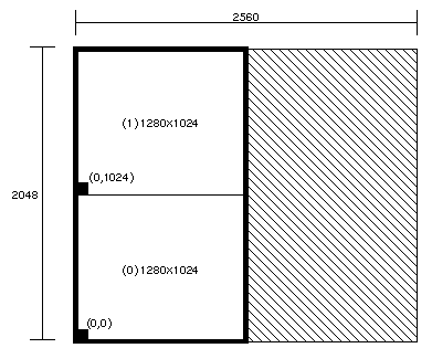
Figure 2-1 shows the maximum single display surface (shaded) and origins for the viewports (unshaded) for the output format 2@1280x1024_60.
| Note: The actual display surface is the largest rectangular area that encloses the viewports (shown in the figure as unshaded). Its size is 1280 x 2048. |
Output of gfxinfo -v for this format is:
Managed 1280x2048 MCO Display 0 1280x1024 @ 60Hz, origin (0, 0) MCO Display 1 1280x1024 @ 60Hz, origin (0, 1024) 8 GE (GE8 rev. 0x7/101) 2 RM4 boards (rev. 00102/00102) Small pixel depth 10-bit RGBA pixels Driving Multi-Channel Option |
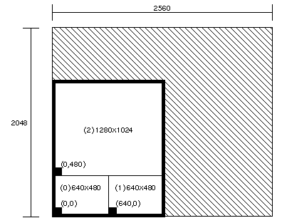
Figure 2-2 shows the maximum single display surface (shaded) and origins for the viewports (unshaded) for the output format 2@640x480_60+1@1280x1024_60.
| Note: The actual display surface is the largest rectangular area that encloses the viewports (shown in the figure as unshaded). Its size is 1280 x 1504. |
Output of gfxinfo -v for this format is:
Managed 1280x1504 MCO Display 0 640x480 @ 60Hz, origin (0, 0) MCO Display 1 640x480 @ 60Hz, origin (640, 0) MCO Display 2 1280x1024 @ 60Hz, origin (0, 480) 8 GE (GE8 rev. 0x7/101) 2 RM4 boards (rev. 00102/00102) Small pixel depth 10-bit RGBA pixels Driving Multi-Channel Option |
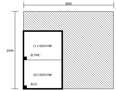
Figure 2-3 shows the maximum single display surface (shaded) and origins for the viewports (unshaded) for the output format 2@1025x768_60.
| Note: The actual display surface is the largest rectangular area that encloses the viewports (shown in the figure as unshaded). Its size is 1025 x 1536. |
Output of gfxinfo -v for this format is:
Managed 1024x1536 MCO Display 0 1025x768 @ 60Hz, origin (0, 0) MCO Display 1 1025x768 @ 60Hz, origin (0, 768) 8 GE (GE8 rev. 0x7/101) 4 RM4 boards (rev. 00102/00102/00102/00102) Small pixel depth 10-bit RGBA pixels Driving Multi-Channel Option |
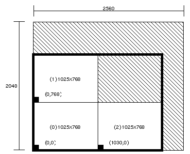
Figure 2-4 shows the maximum single display surface (shaded) and origins for the viewports (unshaded) for the output format 3@1025x768_60.
The third viewport (labeled (2) in Figure 2-4) has its origin (offset) at 1030,0 because it must start on a ten-pixel boundary. This requirement results in an unused five-pixel area between the third viewport and the other two viewports.
| Note: The actual display surface is the largest rectangular area that encloses the viewports (shown in the figure as unshaded). Its size is 2055 x 1536. |
Output of gfxinfo -v for this format is:
Managed 2055x1536 MCO Display 0 1025x768 @ 60Hz, origin (0, 0) MCO Display 1 1025x768 @ 60Hz, origin (0, 768) MCO Display 2 1025x768 @ 60Hz, origin (1030, 0) 8 GE (GE8 rev. 0x7/101) 4 RM4 boards (rev. 00102/00102/00102/00102) Small pixel depth 10-bit RGBA pixels Driving Multi-Channel Option |
IRIX versions 5.0.1, 5.1, 5.1.1, and 5.1.1.2, you must manually reconfigure RealityEngine graphics organization to support 10-bit RGB without alpha. To do so, edit the file /usr/bin/X11/X. The file starts out with:
#! /bin/sh # # /usr/bin/X11/X # initialize graphics device and start X Window System # $Revision: 1.1 $ # glGammaFile=/etc/config/system.glGammaVal glGammaDefault=”1.7” if /etc/chkconfig windowsystem; then if [ -x /usr/gfx/gfxinit ]; then /usr/gfx/gfxinit if [ -r $glGammaFile -a -s $glGammaFile ] ; then |
Modify this file to include these statements between lines 11 and 12:
PIXDENS=PIX32_RGB10 export PIXDENS |
The beginning of the file should look like:
#! /bin/sh # # /usr/bin/X11/X # initialize graphics device and start X Window System # $Revision: 1.1 $ # glGammaFile=/etc/config/system.glGammaVal glGammaDefault=”1.7” if /etc/chkconfig windowsystem; then if [ -x /usr/gfx/gfxinit ]; then PIXDENS=PIX32_RGB10 export PIXDENS /usr/gfx/gfxinit if [ $? -eq 0 -a -x /usr/bin/X11/Xsgi ]; then |
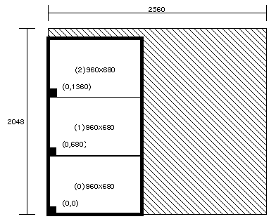
Figure 2-5 shows the maximum single display surface (shaded) and origins for the viewports (unshaded) for the output format 3@960x680_60.
| Note: The actual display surface is the largest rectangular area that encloses the viewports (shown in the figure as unshaded). Its size is 960 x 2040. |
Output of gfxinfo -v for this format is:
Managed 960x2040 MCO Display 0 960x680 @ 60Hz, origin (0, 0) MCO Display 1 960x680 @ 60Hz, origin (0, 680) MCO Display 2 960x680 @ 60Hz, origin (0, 1360) 8 GE (GE8 rev. 0x7/101) 2 RM4 boards (rev. 00102/00102) Small pixel depth 10-bit RGBA pixels Driving Multi-Channel Option |
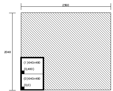
Figure 2-5 shows the maximum single display surface (shaded) and origins for the viewports (unshaded) for the output format 2@640x480_60.
| Note: The actual display surface is the largest rectangular area that encloses the viewports (shown in the figure as unshaded). Its size is 640 x 960. |
Output of gfxinfo -v for this format is:
Managed 640x960 MCO Display 0 640x480 @ 60Hz, origin (0, 0) MCO Display 1 640x480 @ 60Hz, origin (0, 480) 8 GE (GE8 rev. 0x7/101) 2 RM4 boards (rev. 00102/00112) Large pixel depth 10-bit RGBA pixels Driving Multi-Channel Option |
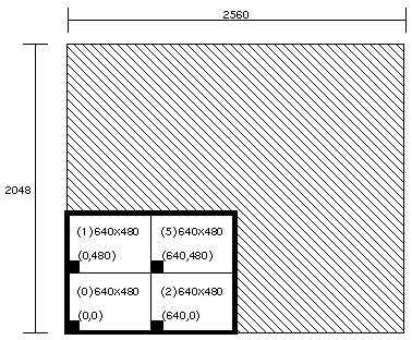
Figure 2-7 shows the maximum single display surface (shaded) and origins for the viewports (unshaded) for the output format 4@640x480_60.
| Note: The actual display surface is the largest rectangular area that encloses the viewports (shown in the figure as unshaded). Its size is 1280 x 960. |
Output of gfxinfo -v for this format is:
Managed 1280x960 MCO Display 0 640x480 @ 60Hz, origin (0, 0) MCO Display 1 640x480 @ 60Hz, origin (0, 480) MCO Display 2 640x480 @ 60Hz, origin (640, 0) MCO Display 5 640x480 @ 60Hz, origin (640, 480) 8 GE (GE8 rev. 0x7/101) 2 RM4 boards (rev. 00102/00102) Large pixel depth 10-bit RGBA pixels Driving Multi-Channel Option |
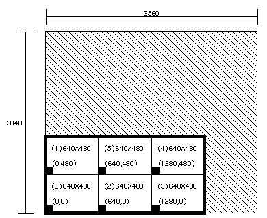
Figure 2-8 shows the maximum single display surface (shaded) and origins for the viewports (unshaded) for the output format 6@640x480_60.
| Note: The actual display surface is the largest rectangular area that encloses the viewports (shown in the figure as unshaded). Its size is 1920 x 960. |
Output of gfxinfo -v for this format is:
Managed 1920x960 MCO Display 0 640x480 @ 60Hz, origin (0, 0) MCO Display 1 640x480 @ 60Hz, origin (0, 480) MCO Display 2 640x480 @ 60Hz, origin (640, 0) MCO Display 3 640x480 @ 60Hz, origin (1280, 0) MCO Display 4 640x480 @ 60Hz, origin (1280, 480) MCO Display 5 640x480 @ 60Hz, origin (640, 480) 8 GE (GE8 rev. 0x7/101) 4 RM4 boards (rev. 00102/00112) Large pixel depth 10-bit RGBA pixels Driving Multi-Channel Option |
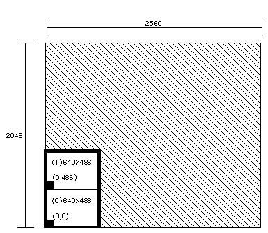
Figure 2-9 shows the maximum single display surface (shaded) and origins for the viewports (unshaded) for the output format 2@640x486_30i (RS-170).
| Note: The actual display surface is the largest rectangular area that encloses the viewports (shown in the figure as unshaded). Its size is 640 x 972. |
Output of gfxinfo -v for this format is:
Managed 640x972 MCO Display 0 640x486 @ 60Hz, origin (0, 0) MCO Display 1 640x486 @ 60Hz, origin (0, 486) 8 GE (GE8 rev. 0x7/101) 2 RM4 boards (rev. 00102/00112) Large pixel depth 10-bit RGBA pixels Driving Multi-Channel Option |
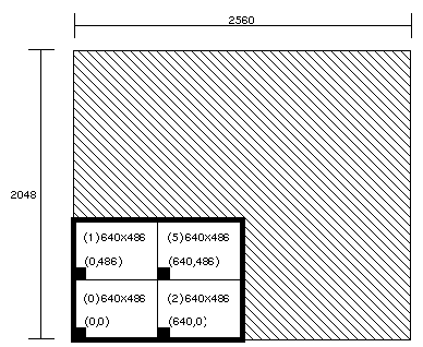
Figure 2-10 shows the maximum single display surface (shaded) and origins for the viewports (unshaded) for the output format 4@640x486_30i (RS-170).
| Note: The actual display surface is the largest rectangular area that encloses the viewports (shown in the figure as unshaded). Its size is 1280 x 972. |
Output of gfxinfo -v for this format is:
Managed 1280x972 MCO Display 0 640x486 @ 60Hz, origin (0, 0) MCO Display 1 640x486 @ 60Hz, origin (0, 486) MCO Display 2 640x486 @ 60Hz, origin (640, 0) MCO Display 5 640x486 @ 60Hz, origin (640, 486) 8 GE (GE8 rev. 0x7/101) 2 RM4 boards (rev. 00102/00112) Large pixel depth 10-bit RGBA pixels Driving Multi-Channel Option |
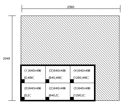
Figure 2-11 shows the maximum single display surface (shaded) and origins for the viewports (unshaded) for the output format 6@640x486_30i (RS-170).
| Note: The actual display surface is the largest rectangular area that encloses the viewports (shown in the figure as unshaded). Its size is 1920 x 972. |
Output of gfxinfo -v for this format is:
Managed 1920x972 MCO Display 0 640x486 @ 60Hz, origin (0, 0) MCO Display 1 640x486 @ 60Hz, origin (0, 486) MCO Display 2 640x486 @ 60Hz, origin (640, 0) MCO Display 3 640x486 @ 60Hz, origin (1280, 0) MCO Display 4 640x486 @ 60Hz, origin (1280, 486) MCO Display 5 640x486 @ 60Hz, origin (640, 486) 8 GE (GE8 rev. 0x7/101) 2 RM4 boards (rev. 00102/00112) Large pixel depth 10-bit RGBA pixels Driving Multi-Channel Option |
This section contains an example program.
#include <stdio.h>
#include <device.h>
#include <gl.h>


/* This program will draw into all Displays allowed by the MCO */
/* First it gets Display number, x-y sizes, */
/* and x-y origins from gfxinfo. */
/* gfxinfo returns information in the following, example, format  */
/*      <blah-blah> */
/*      Managed 1920x1024  */
/*      MCO Display 0 1280x1024 @ 60Hz, origin (0, 0) */
/*      MCO Display 2 1280x1024 @ 60Hz, origin (0, 1024) */
/*      8 GE(s) (GE rev. 0x7) */
/*      2 RM board(s) */
/*      <blah-blah> */
/* Then it draws screen size and origin information into each MCO */
/* Display area */
main()
{

    FILE           *fp;
    char            hz_str[20];
    char            buf[100];
    int             num, sx, sy, xo, yo;

    prefposition(0, getgdesc(GD_XPMAX) - 1, 0, getgdesc(GD_YPMAX) - 1);
    noborder();
    winopen(“MCO test”);
    gconfig();
    color(6);
    clear();

    fp = popen(“/usr/gfx/gfxinfo”, “r”);

    if (!fp) {
	printf(“Could not execute /usr/gfx/gfxinfo\n”);
	exit(0);
    }
    /* first search for `MCO' followed by `Display', */
    /* then scan out the screen number, size and origin. */

    while ((fscanf(fp, “%s”, buf)) != EOF)
	if (strcmp(buf, “MCO”) == 0) {
	    fscanf(fp, “%s”, buf);
	    if (strcmp(buf, “Display”) == 0) {
		fscanf(fp, “%d %dx%d @ %s origin (%d,%d)”,
		       &num, &sx, &sy, hz_str, &xo, &yo);

		/* draw into this screen area */

		label_display(num, sx, sy, xo, yo);
	    }
	}
    pclose(fp);

    while (!getbutton(ESCKEY))
	sginap(1);

}

/* This routine prints information into the MCO screens as they */
/* are scanned from the gfxinfo text */
label_display(int num, int sx, int sy, int xo, int yo)
{
    char            tmp[200];

    pushviewport();
    viewport(xo, xo + sx, yo, yo + sy);
    ortho2(0., 1.0 * sx, 0., 1.0 * sy);
    color(num % 8);
    clear();

    sprintf(tmp, “Display %d size %d x %d at (%d,%d)”, num, sx, sy, xo, yo);
    color((num + 2) % 8);
    cmov2i((sx - strlen(tmp) * 9) / 2, sy / 2);
    charstr(tmp);
    popviewport();
}
|
