This appendix summarizes technical specifications for the Multi-Channel Option hardware:
electrical levels
sync pair outputs
genlock input
format timings
I/O door panel for version with no breakout box
breakout box connectors
Composite sync amplitude is rated into a 75-ohm load. Because calibration is not possible, levels can vary. The electrical levels at the RGB outputs are given in Table A-1.
Specification | Value |
|---|---|
Video amplitude | Into 75 ohms: 1 V peak-to-peak with sync 0.714 V peak-to-peak without sync |
Composite sync | TTL level into 75 ohms |
Separate H and V sync | TTL level into 75 ohms |
Separate composite, horizontal, and vertical sync pair outputs are available for each MCO channel. Use the panel (see Chapter 3, “Using the Multi-Channel Option Panel,”) to turn sync on or off for each video output (for example, sync on green).
The genlock input is a high-impedance input unless a 75-ohm terminator is attached to the second genlock BNC (GEN OUT). A 75-ohm terminator must be attached at the end of the line.
The genlock circuit of the Multi-Channel Option locks to the leading edge of the incoming sync. The Multi-Channel Option can lock to a composite video source or to a composite sync source.
The genlock input level is 1 V peak-to-peak or 2 V to 4 V peak-to-peak. The input signal must conform to the timing and level specifications of the Multi-Channel Option video output format specified using the setmon command, as explained in Chapter 2, “Using setmon,”earlier in this guide.
Table A-2 lists the timings for some Multi-Channel Option video output formats.
Table A-2. Timings for Video Output Formats
Format | Active Width and Height | Total Width and Height | Pixel Clock | Horizontal | Vertical Frequency and |
|---|---|---|---|---|---|
2@1280x1024_60 | 1280 x 1024 | 1680 x 1065 | 107.352000 MHz | 63.900 KHz | 60 Hz noninterlaced |
2@640x480_60+ 1@1280x1024_60 | 640x480 1280x1024 | 800x532 1680x1064 | 25.536000 MHz 107.251200 MHz | 31.920 KHz 63.840 KHz | 60 Hz noninterlaced 60 Hz noninterlaced |
2,3@1025x768_60 | 1025 x 768 | 1320 x 813 | 64.389600 MHz | 48.780 KHz | 60 Hz noninterlaced |
3@960x680_60 | 960 x 680 | 1260 x 720 | 54.432000 MHz | 43.200 KHz | 60 Hz noninterlaced |
2,4,6@640x480_60 | 640 x 480 | 800 x 525 | 25.200000 MHz | 31.500 KHz | 60 Hz noninterlaced |
2,4,6@640x486_30i | 640 x 486 | 780 x 525 | 12.285000 MHz | 15.750 KHz | 30 Hz interlaced (2 fields) |
For information on display surface dimensions, see Chapter 2, “Using setmon,” earlier in this guide.
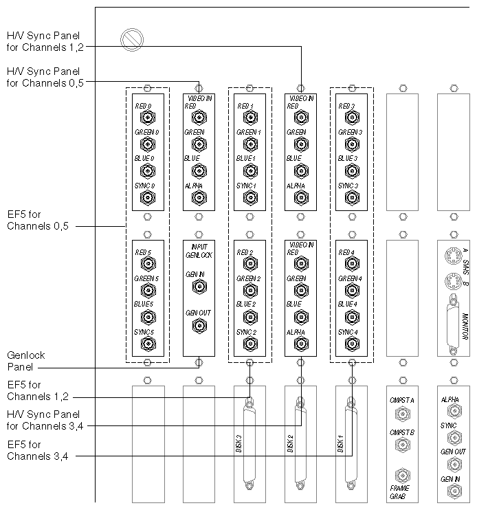
Figure A-1 shows the I/O door panel for a rackmount IRIS chassis with the Multi-Channel Option installed (six channels).
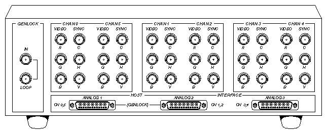
Figure A-2 shows the Multi-Channel Option breakout box.
Table A-3 summarizes breakout box connectors.
Table A-3. Multi-Channel Option Breakout Box Connectors
Section | Connector | Description |
|---|---|---|
GENLOCK | IN LOOP | External sync source (house sync) Loopthrough for genlock input with buffered signal to workstation |
CHAN 0, 5, 1, 2, 3, 4 | VIDEO SYNC | Output to external video Output sync |
HOST INTERFACE | ANALOG 1, 2, 3 | Interface for Multi-Channel Option board via cables from I/O door panels |

