This chapter describes the procedures you should use to correctly install your Challenge deskside front-loading devices (FLDs) into the chassis.
Customer maintenance is limited to the outside of the chassis, which comprises plastic panels, FLDs, customer-related connections, and cables attached to the I/O panel. No user-serviceable parts are located within the chassis. No internal parts or devices should be added to the system by the end user. Doing so may void UL, CSA, and TUV safety agency approvals. Check with your service provider or Silicon Graphics before attempting any internal alteration to the system.
Challenge deskside systems support a sophisticated and complex assortment of SCSI protocols. This results in a lower-cost, high-performance system. It also requires extremely careful attention to proper configuration and connection of drives.
Previous Silicon Graphics systems used differential SCSI exclusively to extend the length of the bus. Your Challenge deskside system uses a differential SCSI bus to communicate directly with fast (20 MB per sec) and wide (16-bit) differential drives.
The Challenge SCSI scheme supports
differential SCSI
single-ended SCSI-1 and SCSI-2
8- and 16-bit transfer protocols
transfer rates of 5 MB, 10 MB, and 20 MB per second
It is important to know the exact type of drive and the protocols it uses before you configure and connect it to your system. If you are unsure, contact your sales representative or service provider before the installation; otherwise, you may degrade SCSI performance or crash your system.
| Note: This product requires the use of external shielded cables in order to maintain compliance with Part 15 of the FCC rules. |
If you are going to have an authorized service provider install peripherals, add external SCSI devices, or reconfigure SCSI bus channels, be sure they understand the rules in the following list.
| Caution: Improper SCSI implementation will cause degraded system performance, a system crash, and/or possible damage to the hardware. |
If you plug a single-ended drive into a bus configured for differential operation, nothing on the bus will work.
If you plug a differential drive into a bus configured as single-ended, the differential drive will not work. Single-ended drives on the bus may continue to work.
Configuration jumpers at the IO4, drive rack backplane, and the sled board must all be set for the same mode or the bus will not work.
Front-loading SCSI devices, both half-height and full-height, that are installed in front-loading bays do not require terminators. Any terminators mounted on a drive should be pulled out before installing a device in a Challenge system.

Caution: Never use a single-ended SCSI terminator on a differential channel. Connecting a single-ended terminator to a differential channel will short +5 V directly to ground, resulting in blown fuses and possible equipment damage. Using a differential terminator on a single-ended bus will cause SCSI bus malfunction.
The service person must follow the guidelines in Table 4-1 to make a SCSI drive work in a deskside system.
Table 4-1. Overview of Drive Installation Guidelines
Drive | Drive Sled Board Channel Configuration | SCSI Rack Backplane Configuration | IO4 Configuration | Transfer Rate Jumpers on SCSI Adapter Board |
|---|---|---|---|---|
8-bit and 16-bit single-ended internal devices | All jumpers in | A22P50 jumper in TRMPWR jumper in A26P52 jumper in | Bus set to single-ended | Both jumpers in |
8-bit and 16-bit single-ended external devices | Not applicable | Not applicable | Bus set to single-ended | Both jumpers out |
8-bit differential | Middle jumpers in | All jumpers in | Bus set to differential | Not applicable |
16-bit differential | Middle jumpers in | All jumpers in | Bus set to differential | Not applicable |
The Challenge deskside chassis uses both half-height and full-height front-loading devices. The power must be off to install or remove storage devices.
FLDs are easily removed and replaced, allowing flexible and secure data management.
| Note: Be careful not to push the drive ID selector when moving the sled release lever to the right. An incorrect SCSI device ID may cause SCSI bus failure. FLDs can be installed and removed with the front door closed and only the drive door open. |
| Caution: Use proper handling and storage procedures to minimize the loss of data and equipment. In particular, do not remove disk drives while they are operating. Always power off the system before removing an FLD. Be sure to use standard electrostatic discharge prevention precautions when removing, storing, transporting, or replacing an FLD. |
Each internally installed FLD must mount on a sled that uses a SCSI channel adapter board. To determine the sled board settings, do the following:
Be sure the sled-to-drive connector cable is plugged into the correct SCSI channel: single-ended(A) or differential (B).
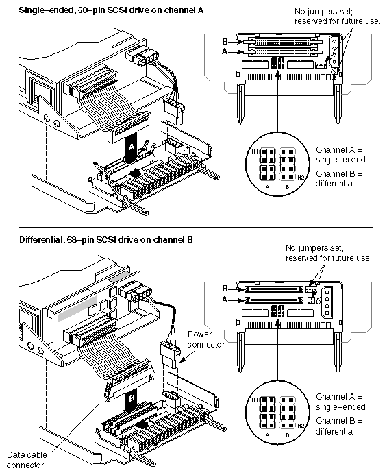
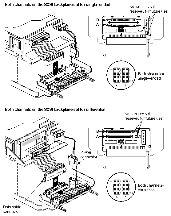
Set both jumper blocks H1 and H2 on the sled board to reflect the SCSI channel operation, regardless of which channel is plugged into the drive (see Figure 4-1).
If the SCSI backplane bus is only single-ended or only differential, set all the jumpers in H1 and H2 for that mode of operation (see Figure 4-1).
The factory shipped your Challenge deskside server with Channel A configured as single-ended and B as differential. If the system has been modified, or if you are uncertain as to the configuration of SCSI Channels A and B, you will have to remove an existing drive. Pull the locking lever on the drive sled to the left and pull the drive and sled assembly gently out of the rack. Compare the settings on the adapter board to those in Figure 4-1 or Figure 4-1. Match the configuration of the new device's adapter board with the intended mode of operation (single-ended or differential).
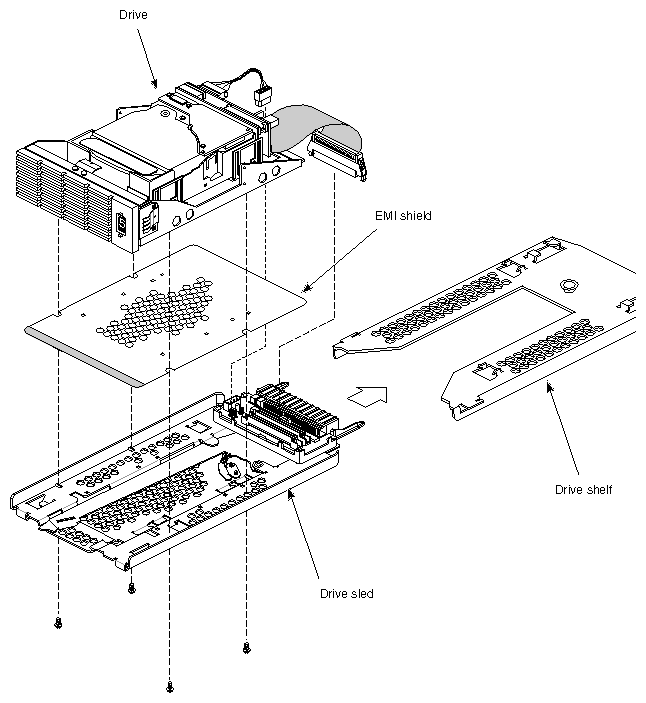
The drive must be properly mounted on a drive sled and configured for a channel and operating protocol (single-ended or differential). See Figure 4-3.
Follow these instructions to install a half-height front-loading device:
If your drive did not come already mounted on a sled, place it on top, as shown in Figure 4-3. Be sure the EMI shield is affixed to the bottom of the drive and is aligned as shown in the drawing.

Note: If your drive did not come with an EMI shield, installation of the part is not necessary. Secure the drive to the bottom of the sled with the four screws provided.
Plug the drive-to-adapter cable into the proper channel connector.
Orient the FLD and sled assembly so that the connectors on the back are on the bottom half of the drive and face away from you.
Carefully insert the device into the drive bay until it seats firmly into the lever catch and the locking lever has moved all the way to the right.
Follow these instructions to remove a front loading device:
Power off the system, as described in Chapter 3.
Open the drive door.
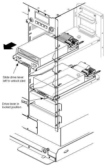
Slide the locking lever on the drive sled all the way to the left and gently pull the drive and sled assembly out. See Figure 4-4.
Each drive must be properly mounted on a drive sled and configured for a particular channel and SCSI transmission protocol (single-ended or differential). Refer to Figure 4-3 for the mounting position of the drive on a sled.
Follow these instructions to install a full-height front loading device:
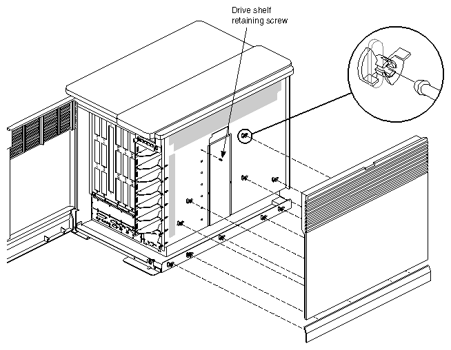
Carefully remove the plastic side panel by first grasping the bottom edge of the panel. See Figure 4-5.
Pull the panel away from the chassis until the ball and socket fasteners release.
Carefully set the panel aside.
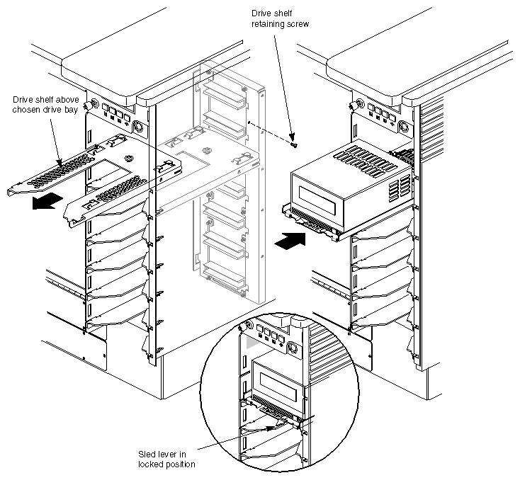
Identify the retaining screw that holds the drive shelf directly above the chosen drive bay, then remove it with a Phillips screwdriver.
Pull the drive shelf straight out of the chassis. See Figure 4-6.

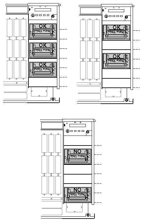
Note: The design of the deskside drive housing precludes placing an optional DLT drive on the third drive shelf down from the top, or the bottom drive shelf. See Figure 4-7 and keep this in mind when preparing for the installation. After removing the drive shelf, the plastic side panel can be replaced by aligning the ball connectors with the sockets in the chassis and reversing steps 1 and 2.
Orient the FLD and sled assembly so that the connectors on the back are on the bottom half of the drive and face away from you.
Carefully insert the device into the drive bay until it seats firmly into the lever catch and the lever will not move any farther to the right. See Figure 4-6.
| Note: Retain the drive shelf if there is a possibility that you will need to install half-height drives at a later date. |
Follow these instructions to prepare the CD-ROM for use:
Install the CD-ROM drive into a half-height slot on the Challenge deskside chassis. Follow the instructions in the previous section to install the FLD.
Find the disc that contains the operating system.
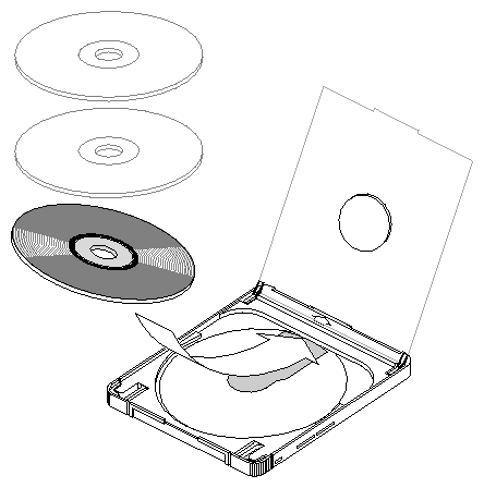
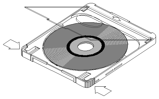
Open the CD-ROM caddy by squeezing the tabs on its sides.
Tilt the CD-ROM into the caddy, as shown in Figure 4-8. The CD-ROM fits under the groove at the end of the caddy.
Close the caddy.
Hold the caddy by its tabs and orient it as shown in Figure 4-9.
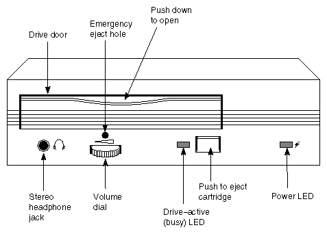
Slide the caddy into the CD-ROM drive; see Figure 4-10 for the location of the drive door.
See the IRIX Admin: Software Installation and Licensing manual for complete instructions on loading software.
Load IRIX 5.3 or later; 6.0 or later for POWER Challenge; or IRIX 6.2 or later for the Challenge 10000 or POWER Challenge 10000, from the initial prompt. Select 2, as shown in the following example menu, to load the operating system from a CD-ROM FLD.:
System Maintenance Menu:
 1) Start System
 2) Install System Software
 3) Run Diagnostics
 4) Recover System
 5) Enter Command Monitor

 Option? 2 <Enter>

Installing System Software...
Press <Esc> to return to the menu.

1) Remote Tape 2) Remote Directory X) Local CD-ROM X) Local Tape

 Enter 1-4 to select source type, <Esc> to quit,
 or <Enter> to start: :
If a CD-ROM or Local Tape is attached, a number will be listed next to them instead of an 'X'.
A series of dots appears as the operating system loads.
See Appendix B for information on proper maintenance and use of your CD-ROM drive and discs.
| Note: Do not insert the disc into the drive without a caddy. |
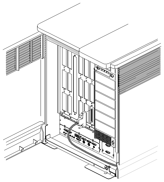
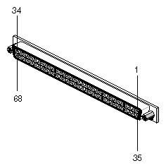
External SCSI devices connect to the system using an optional 68-pin differential (DF SCSI) or single-ended (SE SCSI) connector that must first be installed on the I/O panel. Figure 4-11 illustrates how to connect an external SCSI device. Table 4-2 and Table 4-3 provide pinout information for these connectors.
The external SCSI connector on Challenge products does not come as a standard, pre-connected feature from the factory. The external SCSI connector must be connected and configured by a trained field installer during or after the installation of the deskside system.
| Note: A differential connector is labeled DF SCSI and a singled-ended connector is labeled SE SCSI. |
The hyphen preceding a signal name indicates that the signal is low. Note that 8-bit devices that connect to the P-cable leave these signals open: -DB(8), -DB(9), -DB(10), -DB(11), -DB(12), -DB(13), -DB(14), -DB(15), -DB(P1). All other signals are connected as shown in Table 4-2.
Table 4-2. 68-Pin Single-Ended, High-Density SCSI Pinouts
Signal Name | Pin Number | Pin Number | Signal Name |
|---|---|---|---|
Ground | 1 | 35 | -DB(12) |
Ground | 2 | 36 | -DB(13) |
Ground | 3 | 37 | -DB(14) |
Ground | 4 | 38 | -DB(15) |
Ground | 5 | 39 | -DB(P1) |
Ground | 6 | 40 | -DB(0) |
Ground | 7 | 41 | -DB(1) |
Ground | 8 | 42 | -DB(2) |
Ground | 9 | 43 | -DB(3) |
Ground | 10 | 44 | -DB(4) |
Ground | 11 | 45 | -DB(5) |
Ground | 12 | 46 | -DB(6) |
Ground | 13 | 47 | -DB(7) |
Ground | 14 | 48 | -DB(P) |
Ground | 15 | 49 | Ground |
Ground | 16 | 50 | Ground |
TERMPWR | 17 | 51 | TERMPWR |
TERMPWR | 18 | 52 | TERMPWR |
Reserved | 19 | 53 | Reserved |
Ground | 20 | 54 | Ground |
Ground | 21 | 55 | -ATN |
Ground | 22 | 56 | Ground |
Ground | 23 | 57 | -BSY |
Ground | 24 | 58 | -ACK |
Ground | 25 | 59 | -RST |
Ground | 26 | 60 | -MSG |
Ground | 27 | 61 | -SEL |
Ground | 28 | 62 | -C/D |
Ground | 29 | 63 | -REQ |
Ground | 30 | 64 | -I/O |
Ground | 31 | 65 | -DB(8) |
Ground | 32 | 66 | -DB(9) |
Ground | 33 | 67 | -DB(10) |
Ground | 34 | 68 | -DB(11) |
The hyphen preceding a signal name indicates that the signal is low. Note that 8-bit devices that connect to the P-cable leave these signals open: -DB(12), -DB(13), -DB(14), -DB(15), -DB(P1), -DB(8), -DB(9), -DB(10), -DB(11), +DB(12), +DB(13), +DB(14), +DB(15), +DB(P1), +DB(8), +DB(9), +DB(10), +DB(11). All other signals are connected as shown in Table 4-3.
Table 4-3. 68-Pin Differential, High-Density SCSI Pinouts
Signal Name | Connector Contact Number | Cable Contact Number | Signal Name |
|---|---|---|---|
+DB(12) | 1 | 35 | -DB(12) |
+DB(13) | 2 | 36 | -DB(13) |
+DB(14) | 3 | 37 | -DB(14) |
+DB(15) | 4 | 38 | -DB(15) |
+DB(P1) | 5 | 39 | -DB(P1) |
Ground | 6 | 40 | Ground |
+DB(0) | 7 | 41 | -DB(0) |
+DB(1) | 8 | 42 | -DB(1) |
+DB(2) | 9 | 43 | -DB(2) |
+DB(3) | 10 | 44 | -DB(3) |
+DB(4) | 11 | 45 | -DB(4) |
+DB(5) | 12 | 46 | -DB(5) |
+DB(6) | 13 | 47 | -DB(6) |
+DB(7) | 14 | 48 | -DB(7) |
+DB(P) | 15 | 49 | -DB(P) |
DIFFSENS | 16 | 50 | Ground |
TERMPWR | 17 | 51 | TERMPWR |
TERMPWR | 18 | 52 | TERMPWR |
Reserved | 19 | 53 | Reserved |
+ATN | 20 | 54 | -ATN |
Ground | 21 | 55 | Ground |
+BSY | 22 | 56 | -BSY |
+ACK | 23 | 57 | -ACK |
+RST | 24 | 58 | -RST |
+MSG | 25 | 59 | -MSG |
+SEL | 26 | 60 | -SEL |
+C/D | 27 | 61 | -C/D |
+REQ | 28 | 62 | -REQ |
+I/O | 29 | 63 | -I/O |
Ground | 30 | 64 | Ground |
+DB(8) | 31 | 65 | -DB(8) |
+DB(9) | 32 | 66 | -DB(9) |
+DB(10) | 33 | 67 | -DB(10) |
+DB(11) | 34 | 68 | -DB(11) |
A serial printer can be connected to your system by connecting a printer or null modem cable to one of the 9-pin RS-232 serial connectors on the I/O panel. Printers vary, but if you are building a 9- to 25-pin cable connection, the pins typically map as shown in Table 4-4.
Table 4-4. Typical DTE to DTE Serial Printer Connection
System Connector Signal | Pin # | 25-Pin Connector to Printer |
|---|---|---|
Transmitted Data (TXD) | 2 | 3 (RXD) |
Received Data (RXD) | 3 | 2 (TXD) |
Request to Send (RTS) | 4 | 5 (CTS) |
Clear to send (CTS) | 5 | 4 (RTS) |
Signal Ground (GND) | 7 | 7 (GND) |
Data Terminal Ready (DTR) | 9 | 6 Data Set Ready (DSR) |
Once you are sure that your cable is correctly configured, use the following procedure to connect a printer to your system:
Make sure that the power switch on the printer is turned off and the power cord is not connected to an outlet.
Attach the printer cable to the printer.
Open the main door of the cabinet to expose the I/O panel.
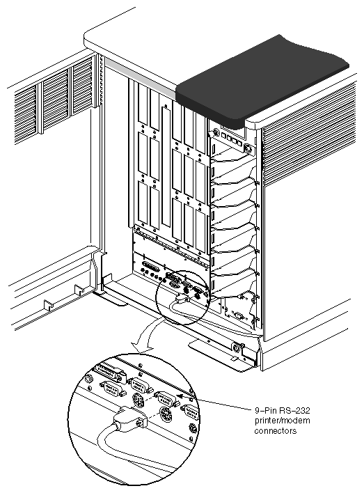
Attach the 9-pin connector on the other end of the printer cable to one of the 9-pin serial connectors on the I/O panel, as shown in Figure 4-14.
Attach the printer power cord and turn on the printer.
Your serial printer must work in concert with the LP spooling system that your Challenge deskside server uses. The LP spooling system allows you to add or remove printers, and to change interface programs, devices, and the system default printer. Be sure to read the documentation that comes with your printer.
Use the following guidelines only as an example procedure for setting up a serial printer.
To add a dumb printer to serial port 2:
Become superuser and change the ownership of the printer device file:
# chown lp /dev/ttyd2
Change the permissions of the printer device file:
# chmod 600 /dev/ttyd2
Edit the inittab file using vi or your favorite line editor, and confirm that port 2 under “on-board ports” reads as follows:
# vi /etc/inittab
t2:23:off:/etc/getty -N ttyd2 co_9600		 # port 2
Modify the line, if necessary, and reprocess the inittab file:
# telinit q
Configure the LP spooling system for your dumb printer:
# /usr/lib/lpadmin -pEPSON -vttyd2 -mdumb
Start the print spooler:
# /usr/lib/lpsched
Enable the printer to accept print requests:
# /usr/lib/accept EPSON
Activate the printer:
# enable EPSON
To add a PostScript® serial printer to port 2, become the superuser, and enter the following:
# mkPS PostScript ttyd2 # /usr/lib/lpadmin -dPostScript |
Refer to the IRIX Admin: Peripheral Devices manual for more information about configuring your printer.
You can connect an optional ASCII terminal to your server by using a simple null modem cable with a 9-pin connector. See Table 4-4 for the serial port to null modem cable pin assignments. Connect one end of the cable to the terminal and the other end to the 9-pin system console port labeled tty_1 on the main I/O panel. If you are building a 9- to 25-pin cable connection, the pins typically map as shown in Table 4-5.
Table 4-5. Typical ASCII Terminal Connection
System Connector Signal | Pin # | 25-Pin Connector to Terminal |
|---|---|---|
Transmitted Data (TXD) | 2 | 3 (RXD) |
Received Data (RXD) | 3 | 2 (TXD) |
Signal Ground (GND) | 7 | 7 (GND) |
The ASCII terminal must be set with the following operational characteristics:
9600 baud
8 bits
1 stop bit
No parity
For your ASCII terminal to operate properly as the system console, it must be plugged into the RS-232-compatible connector labeled tty_1 on the system I/O panel.
To attach an ASCII terminal, complete the following steps:
Locate the RS-232 connector designated for the console and labeled tty_1.
Attach one end of the console cable to the RS-232 connector and route it out the back of the unit.
Connect the other end to the 9-pin connector on the null modem cable and plug the 25-pin null modem connection into the system console terminal.
Attach the keyboard and power connectors to the terminal.

Caution: Before plugging the terminal into either a 110 VAC or a
220 VAC outlet, be sure that the electrical rating on the UL-CSA label is in either the 100–120 VAC or the 200–240 VAC range, whichever applies.Power on the terminal before restarting your system.
Restart the system or continue with other peripheral connections as needed.
Your console terminal needs recognition from the system software. Be sure to read the documentation that comes with the terminal. Use the following guidelines to help check and confirm the setup of your console terminal:
Become superuser and choose the proper baud rate, prompt, and line conditioning from the /etc/gettydefs file.
# vi /etc/gettydefs
Modify the file /etc/inittab, if necessary, to enable getty on port tty_1. The line is listed under “on-board ports” and should appear as shown below:
# vi /etc/inittab
t1:23:respawn:/etc/getty ttyd1 co_9600 	 # alt console
After modifying the /etc/inittab file, inform init of any changes by entering the following:
# telinit q
Look in /etc/ttytype for the listed console port information. To keep the system from asking you what type of terminal you are using when you log in, remove the question mark.
Add the following line to your ~/.login file. This sets the terminal type, syntax, and erase/kill parameters automatically when you log in:
% eval `tset -s -Q'
Check terminal connection and function using the following:
% cat /etc/group > /dev/ttyd1
% ps -def | grep getty
To show the standard settings on a particular serial port, become superuser and enter
# stty < /dev/ttydx |
where x is the number of the tty port on which you want information.
To show the various settings on a particular serial port, enter
# stty -a < /dev/ttydx |
To change the baud rate on a particular serial port, enter the following (the example is 2400):
# stty 2400 < dev/ttydx |
For additional useful information on serial ports and configuration, see the reference (man) pages for the following:
inittab
gettydefs
ttytype
terminfo
stty
termio
The following files are most commonly used to properly configure serial port operation for the server:
/etc/inittab
/etc/gettydefs
/etc/ttytype
/usr/lib/terminfo
/etc/uucp/Systems
A modem can be connected to your system by connecting a modem cable to one of the 9-pin serial connectors on the I/O panel. The pin assignments are listed in Table 4-6. A 9-pin to 25-pin cable may be required. Silicon Graphics supports Hayes 2400 and Telebit modems. Edit the /etc/uucp/fix-hayes or /etc/uucp/fix-telebit files for information on specific models supported (see step 7 on the next page).
Be sure that the pin assignments, not the pin numbers, on the Challenge system's serial port are properly matched to the pin assignments on your modem.
Table 4-6. RS-232 Modem Connector Pin Assignments
9-Pin Connector Pin | 25-Pin Connector Pin | Signal Description at Host |
|---|---|---|
2 | 2 | Transmitted Data (TXD) |
3 | 3 | Received Data (RXD) |
4 | 4 | Request to Send (RTS) |
5 | 5 | Clear to Send (CTS) |
7 | 7 | Signal Ground (GND) |
8 | 8 | Data Carrier Detect (DCD) |
9 | 20 | Data Terminal Ready (DTR) |
Once you are sure that your cable is correctly configured, use the following general procedures to connect a modem to your system:
Make sure that the power switch on the modem is turned off.
Attach the cable to the modem.
Open the main door of the chassis to expose the I/O panel.
Attach the connector on the other end of the cable to one of the
9-pin serial connectors on the I/O panel, as shown in Figure 4-14.Read the documentation that comes with your modem to determine model-specific connection and configuration procedures.
Attach the modem power cord and turn on the modem.
Install the eoe2.sw.uucp subsystem if it is not already installed.
| Note: The eoe2.sw.uucp subsystem is shipped with each copy of the IRIX operating system, but is not installed by default. Confirm that eoe2.sw.uucp is installed by using the versions command. If it is not installed, see the IRIS Software Installation Guide for instructions. |
Refer to the IRIX Advanced Site and Server Administration Guide for additional information about configuring modems. Entries in the /etc/inittab and /etc/uucp/Devices files may need to be modified.
Additional useful information on modem operation and configuration is available in the reference (man) pages for the following:
dial
cu
To attach a parallel printer, complete the following steps:
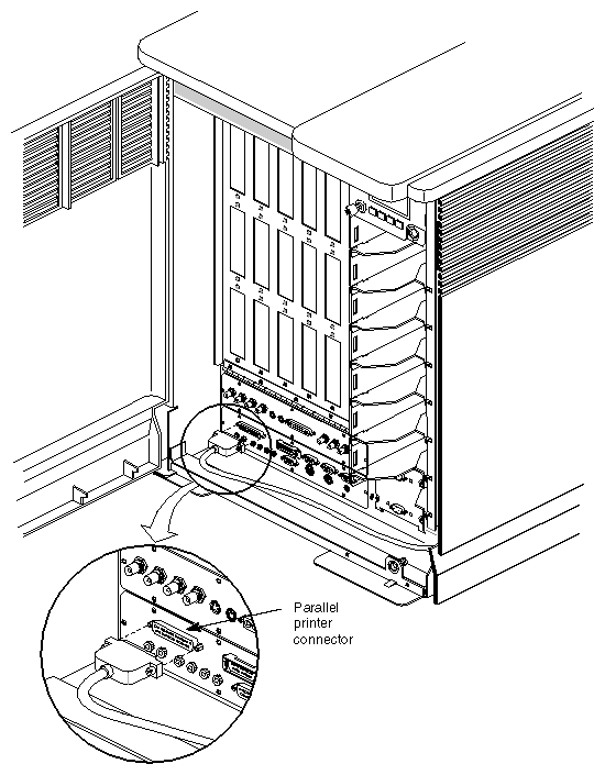
Locate the 25-pin, sub-D parallel connector on the main I/O panel (see Figure 4-15).
Attach one end of the cable to the connector and route it out the back of the unit.
Connect the other end to the parallel printer. Be sure you have confirmed pin and signal compatibility before making the connection. (See Table 4-7.)

Caution: Before plugging the printer into either a 110 VAC or a 220 VAC outlet, be sure that the electrical rating on the label is in either the 100–120 VAC or the 200–240 VAC range, whichever applies. Turn on the printer before restarting your system.
Restart the system or continue with other peripheral connections as needed.
To enable the serial port on any optional additional IO4 boards, enter the following as the superuser:
# cd /dev
# ./MAKEDEV plp
The MAKEDEV command checks the system's hardware configuration and makes parallel port device nodes for all possible ports.
Your parallel printer must work in concert with the LP spooling system that your Challenge deskside server uses. The LP spooling system allows you to add or remove printers and to change interface programs, devices, and the system default printer. Be sure to read the documentation that comes with your parallel printer.
Use the following instructions only as an example procedure:
Become superuser and configure the LP spooling system (the 03 in -vplp03 represents the Ebus slot where the IO4 board is):
# /usr/lib/lpadmin -pTekprinter -vplp03
Start the print spooler:
# /usr/lib/lpsched
Enable the printer to accept print requests:
# /usr/lib/accept Tekprinter
Activate the printer:
# enable Tekprinter
Refer to the IRIX Admin: Peripheral Devices manual for additional information about configuring your parallel printer.
The parallel printer port on the system I/O panel is a 25-pin, Centronics compatible connector. Table 4-7 shows the pin assignments and signals as they relate to a 36-pin Centronics connector.
Table 4-7. Centronics Compatible Parallel Port Pin Assignments
25-Pin Serial Port Pin Assignment | 36-Pin Centronics Pin Assignments | Signal |
|---|---|---|
1 | 1 | STB (Data Strobe) |
2 | 2 | DATA 0 |
3 | 3 | DATA 1 |
4 | 4 | DATA 2 |
5 | 5 | DATA 3 |
6 | 6 | DATA 4 |
7 | 7 | DATA 5 |
8 | 8 | DATA 6 |
9 | 9 | DATA 7 |
10 | 10 | DATA ACK |
11 | 11 | BUSY |
12 | 12 | PE (Paper Empty) |
13 | 13 | SLCT (Select) |
14 | N/A | AUTOFD |
15 | 32 | ERROR |
16 | N/A | INIT (Reset) |
17 | N/A | SLCTIN |
18 through 25 | 20 through 27 | GND |
