This chapter describes the major features of the Challenge deskside server chassis, along with its controls, connectors, and indicators.
| Warning: To avoid electric shock and to prevent a fire hazard, do not disassemble the Challenge system. No user-serviceable parts are located within the chassis. All installation and maintenance must be performed by Silicon Graphics-trained personnel. Contact the Silicon Graphics Technical Education department for information about customer training. |
This chapter is intended to give you a better overall understanding of Challenge deskside systems. It is not intended as a guide for system disassembly or removal/replacement of components, except where end-user access is specified.
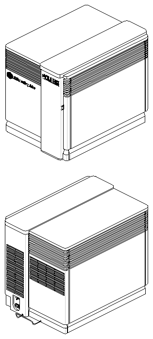
The Challenge deskside chassis houses all boards, drives, and other components in a single, upright enclosure. With its small physical dimensions and quiet operation, the chassis fits into a lab, server room, or normal office environment. Figure 2-1 shows the external appearance of the Challenge deskside chassis.
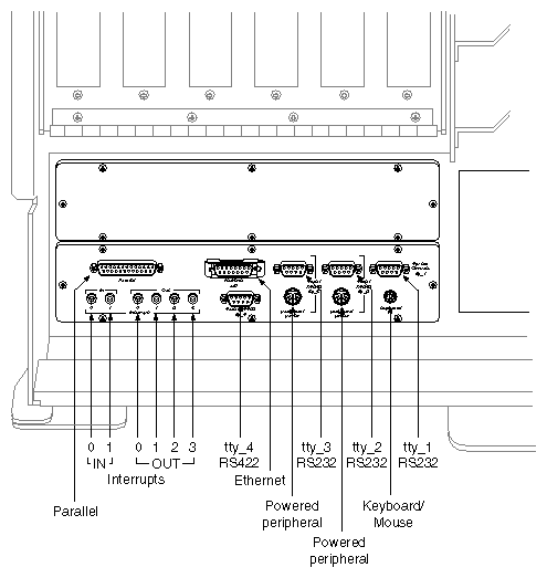
The Challenge deskside chassis is a compact unit that contains an 11-slot cardcage, system boards, a power supply, and selected peripherals and cables. System connector locations are indicated in Figure 2-2, and connector descriptions are listed in Table 2-2.
The I/O panel is used to connect external devices to the Challenge deskside system. These devices include the system console terminal, a printer, and a modem. Specific instructions for connecting these devices are located in Chapter 3, “Getting Started.”
The I/O panel configuration for the basic server board set is shown in Figure 2-2.
Table 2-2 describes the standard I/O interface connectors that come with the Challenge deskside system shown in Figure 2-2. They are listed from left to right, starting with the parallel printer connector.
| Note: If you disconnect a cable from a peripheral device, you should also disconnect it from the I/O connector on the I/O panel. This helps prevent the system from picking up external electrical noise. |
The single-jack interrupt ports require stereo-audio type 3.5 mm plug connectors with shielded cables. These plugs are not for use with headphones, microphones, and so on.
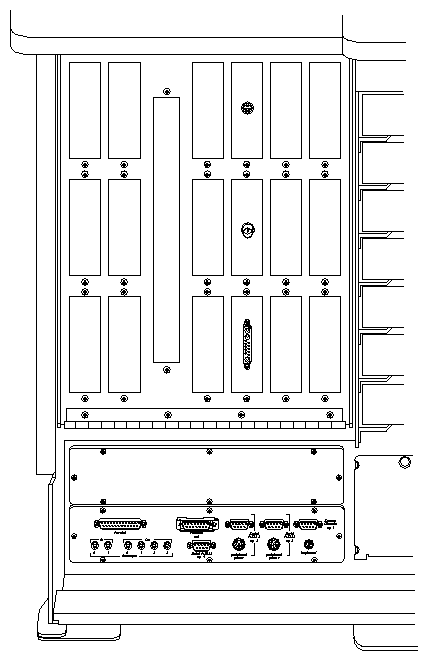
The I/O panel configuration for the Extreme graphics optional visualization console is shown in Figure 2-3. Table 2-2 lists the connector types and descriptions for the visualization console option.
Table 2-1. Standard I/O Connectors
Connector Type | Connector Description | Connector Function |
|---|---|---|
25-Pin sub-D parallel | Centronics® compatible parallel port | Drives parallel printer |
15-Pin sub-D Ethernet | 15-Pin Ethernet | Standard AUI Ethernet connection |
9-Pin sub-D RS-232 or round 8-pin DIN powered RS-232 | RS-232 serial port tty_3 (Use only one connector) | Supports either RS-232 powered or unpowered serial interface |
9-Pin sub-D RS-232 or round 8-pin DIN powered RS-232 | RS-232 serial port tty_2 (Use only one connector) | Supports either RS-232 powered or unpowered serial interface |
9-Pin sub-D RS-232 | RS-232 serial port tty_1 | Supports RS-232 Serial Interface for System Console Terminal |
3.5-mm tip-ring-sleeve interrupt 0-1 input jacks | Single jack plugs | External interrupt to system |
3.5-mm tip-ring-sleeve interrupt 0-3 output jacks | Single jack plugs | Interrupt generation to external system |
9-Pin sub-D RS-422 | RS-422 serial port tty_4 | Supports RS-422 Serial Interface |
6-Pin mini DIN | Keyboard connector | Supports keyboard and mouse |
Table 2-2. Optional Visualization Console Video Connector Description
Connector Type | Connector Description |
|---|---|
Video | 13W3 |
Genlock | BNC |
Stereoview | 4-pin powered peripheral |
The Challenge system provides three types of serial ports.
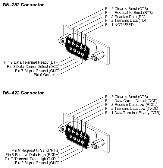
A 9-pin RS-232 unpowered D-sub connector (see Figure 2-4)
A 9-pin RS-422 unpowered D-sub connector (see Figure 2-4)
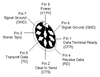
An 8-pin RS-232 powered DIN connector (see Figure 2-5)
| Caution: Neither of the two RS-232 connectors conform to EIA/TIA industry standards, so a serial cable must either be ordered through a Silicon Graphics supplier or be specially constructed. |
Both powered and unpowered serial connectors are provided on the Challenge deskside system. Terminals, modems, printers, and other peripherals with independent power sources use the 9-pin sub-D connectors (see Figure 2-4 and Table 2-3). Powered peripherals use a circular 8-pin DIN connector for data and DC power (see Figure 2-5 and Table 2-3).
Each serial port supports one device. Do not attach (daisy-chain) more than one device to each sub-D or DIN connector. For ports tty_2 and tty_3, you must use either the 8-pin powered connector or the 9-pin sub-D; you cannot use both simultaneously.
For all POWER Challenge and Challenge systems, Silicon Graphics recommends the use of RS-232 serial cables no longer than 30 feet (9.15 meters). Longer runs introduce a greater possibility of line noise occurring. This can affect data transmission and cause errors. For cable runs longer than 30 feet (9.15 meters), use an appropriate extender device.
Do not run cables through areas that are electrically noisy, such as areas where large electric motors, welding apparatus, or X-ray machines operate. Bury outside wiring in conduit, as lighting strikes can damage the system.
Table 2-3. RS-232 (9-Pin Unpowered) and RS-422 Connector Detail
Connector Type | Description | Pin Number | Signal | Flow from chassis |
|---|---|---|---|---|
RS-232 (see Figure 2-4) | Serial port tty1 RS-232 protocol. Serial ports 0 and 1 provide a choice of this or an 8-pin DIN receptacle. Only one receptacle from each port can be used at a given time. | 1 2 3 4 5 6 7 8 9 | not used TXD RXD RTS CTS GND GND DCD DTR |
output input output input
input output |
RS-232 (see Figure 2-4) | Serial ports tty2, tty3
for unpowered
peripherals. RS-232 protocol. Serial ports 0 and 1 provide a choice of this or an 8-pin DIN receptacle. Only one receptacle from each port may be used at a given time. | 1 2 3 4 5 6 7 8 9
| not used TXD RXD RTS CTS GND GND DCD DTR
|
output input output input
input output
|
RS-422 (see Figure 2-4) | Serial port tty4 RS-422 protocol. 9-pin D-sub receptacle. | 1 2 3 4 5 6 7 8 9 | DTR TXD low -1 RXD low -2 DCD CTS GND TXD high +1 RXD high +2 RTS | output output input input input
output input output |
1 Pins 2 and 7 must be a twisted pair in cable. 2 Pins 3 and 8 must be a twisted pair in cable. |
|
|
|
|
Table 2-4. RS-232 (8-Pin Powered) Connector Detail
Connector Type | Description | Pin Number | Signal | Flow from chassis |
|---|---|---|---|---|
RS-232 (see Figure 2-5) | Serials ports tty2, tty3
for powered
peripherals.
| 1 2 3 4 5 6 7 8 | DTR CTS Stereo Sync RXD TXD GND GND Power +10V | output input output input output
output |
Use the steps in the following example (if necessary) to enable the additional serial ports provided when you order an optional IO4.
Edit the file /var/sysgen/system/irix.sm.
Find a line that looks similar to the following:
*VECTOR: bustype=EPC module=epcserial unit=1 slot=? ioa=1
Remove the leading “*” and enter the appropriate slot number of the additional IO4 that has serial ports that require enabling. For example, you would change the question mark after slot= to a 4 if an additional IO4 was installed in slot 4.
VECTOR: bustype=EPC module=epcserial unit=1 slot=4 ioa=1
Write and quit the file, then rebuild the kernel (using the /etc/autoconfig command).
Reboot the system and create the appropriate device nodes by entering /dev/MAKEDEV ttys. This should create something like the following:
/dev/ttyd45 Major=0, Minor=5:
/dev/ttyd46 Major=0, Minor=6:
/dev/ttyd47 Major=0, Minor=7:
/dev/ttyd48 Major=0, Minor=8:
/dev/ttyf45 Major=0, Minor=101:
/dev/ttyf46 Major=0, Minor=102:
/dev/ttyf47 Major=0, Minor=103:
/dev/ttyf48 Major=0, Minor=104:
/dev/ttym45 Major=0, Minor=37:
/dev/ttym46 Major=0, Minor=38:
/dev/ttym47 Major=0, Minor=39:
/dev/ttym48 Major=0, Minor=40:
Additional connector labeling information is shown in Table 2-5.
Table 2-5. Server System IO4 Board Connector Labelling
IO4 Board Number
IO4 Filter Board Label (Server)
Serial Connectors
Server Parallel Connectors
Network Connectors
1
EBus 5
RS-232: tty1-3 [a] RS-422: tty4
plp5
et0
2
EBus 4
tty45-47 [b]
plp4
et1
3
EBus 3
tty49-51b
plp3
et2
[a] Connectors are labelled sequentially from right to left.
[b] Connectors are labelled sequentially from top to bottom.
Edit the /etc/inittab file and change the word “off” to “respawn” in the line associated with the ttys you have just enabled.

Note: Since there is no I/O panel connection for the RS-422 port (which corresponds in this example to ttyd48), there is no reason to change it. Enter telinit q to force the init process to reread /etc/inittab and create gettys on the additional RS-232 ports.
Device nodes of the form tty[fm]* are for use with modems. For additional information on these topics, see the reference (man) pages for:
getty(1M)
uugetty(1M)
init(1M)
gettydefs(4)
inittab(4)
Note that comments in the file /etc/inittab are somewhat outdated and can be potentially confusing as they refer to nomenclature and architecture of older Silicon Graphics systems when referring to serial ports. When “I/O” board is mentioned you should infer “VME serial I/O controller,” and where “CPU board” is mentioned you should read “IO4 board.”
The parallel printer port on the system I/O panel is a 25-pin, Centronics- compatible connector. Table 2-6 shows the pin assignments and the signals that they carry.
| Note: The optimum recommended length for a cable used with this parallel port is 10 feet (3 meters). Maximum length should not exceed 20 feet (6 meters). |
To enable an additional parallel printer port on an optional IO4 installed in your Challenge deskside, input the following:
% cd /dev # ./MAKEDEV plp |
These commands create the necessary device nodes required to use the additional parallel port on an optional IO4. The MAKEDEV command automatically checks the hardware configuration of your Challenge and makes parallel port device nodes for additional ports.
Table 2-6. Centronics Compatible Parallel Port Pin Assignments
Pin | Assignment |
|---|---|
1 | STB (Data Strobe) |
2 | DATA 0 |
3 | DATA 1 |
4 | DATA 2 |
5 | DATA 3 |
6 | DATA 4 |
7 | DATA 5 |
8 | DATA 6 |
9 | DATA 7 |
10 | DATA ACK |
11 | BUSY |
12 | PE (Paper Empty) |
13 | SLCT (Select) |
14 | AUTOFD |
15 | ERROR |
16 | INIT (Reset) |
17 | SLCTIN |
18 through 25 | GND |
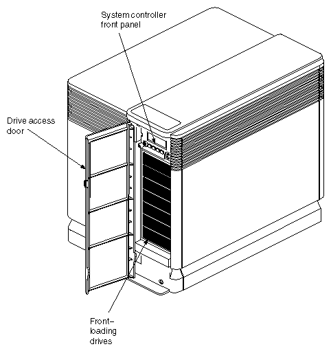
A narrow front door on the right side of the chassis allows you to access the System Controller front panel and install front-loading devices in the drive rack. The System Controller panel is located just above the drive rack. Figure 2-6 shows the location of the key switch and indicators on the System Controller front panel.
The position of the key switch determines what mode the System Controller is monitoring (see Figure 3-4). Press the Menu button for a display of executable options. The Scroll Up and Scroll Down buttons allow you to move up and down through the menu list and scroll through a 10-message error file within the menu. Press the Execute button, and the System Controller performs the option that is listed.
The key switch on the System Controller front panel serves two purposes:
It turns the system boards and peripherals on and off.
When the key switch is in the On position, and the key is removed, it prevents unauthorized shutdown or alteration of system operations from the control panel.
When the key switch is in the On position, no alteration of system function can be executed from the front panel menus. If the switch is moved into the Manager position, system operations can be modified, reset, or limited. Access to the Manager functions should be limited to trained system administrators and service personnel only.
| Note: Always remove the key from the System Controller's front panel before closing the front door covering the LCD panel and drive bays. For a detailed description of how to use the System Controller, see the System Controller information in Chapter 5, “Troubleshooting.” |
The SCSI drive rack (shown in Figure 2-5) is a vertically oriented enclosure, with seven half-height drive bays. Each bay is defined by a sheet-metal drive tray. The SCSI drive sled slides into the tray and locks in place with its connectors pushed into the SCSI backplane. The sheet-metal drive trays can be removed to allow the installation of full-height devices.
The internal SCSI backplane provides a maximum of two SCSI channels. The channels are terminated on the backplane and are not used to control externally mounted SCSI devices. The channels are compatible with either 8-bit or 16-bit SCSI buses, and they are configured at the factory to support single-ended and differential SCSI devices in the drive rack. Channel A is set to single-ended and channel B to differential operation.
| Note: It is important that the operational setting on the drive sled printed circuit board agree with the setting of the IO4 SCSI channel. If you are installing a single-ended device in the internal rack, the drive should be plugged into channel A on the sled board. If you are installing a differential device, it should plug into channel B on the sled board. Chapter 4 provides details of what happens if you violate these guidelines. |
| Caution: Never plug a front-loading or external SCSI device into your Challenge system while it is powered on. |
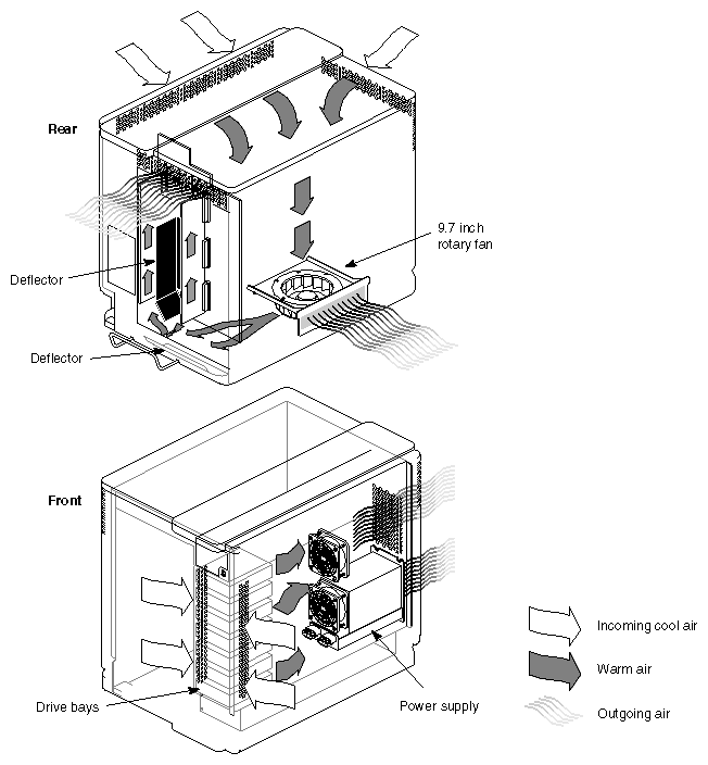
The Challenge deskside chassis is cooled by a combination of one rotary “blower box” and two conventional 5-inch (12.7-cm) fans that draw in ambient air. The 9.7-inch (24.6-cm) vaned rotor provides the main chassis cooling by drawing air in through openings near the top and exhausting it out the lower side and rear. See Figure 2-7.
One 5-inch fan cools the system power supply, while the other draws air from front to back, helping to cool the drive tray assembly.
| Caution: Never operate your Challenge system with any of its sheet-metal panels open or removed. The system will overheat, and damage to internal components may result. |
The vaned rotor is in contact with the System Controller and changes speed to provide more or less airflow, depending on the temperature of incoming air (see Figure 2-7). These changes are initiated by a temperature sensor that helps the System Controller adjust the rotor fan for efficient cooling with the lowest possible noise level.
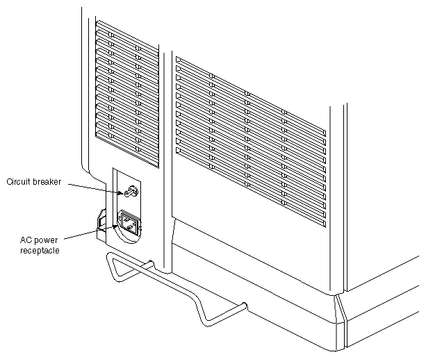
AC voltage feeds into a power receptacle and circuit breaker assembly located on the lower left rear panel of the Challenge deskside system. The circuit breaker switch controls the main power supply to the chassis and provides alternating current (AC) circuit protection. The power receptacle and circuit breaker are shown in Figure 2-8.
The Challenge deskside system is available as either a 110 VAC or 220–240 VAC system. Certain system configurations or upgrades may require the use of a 220–240 VAC supply; check with your sales or service representative.
Voltage is routed into a special power supply known as an offline switcher (OLS). The OLS supplies up to 1900 watts of power to the chassis backplanes by converting the AC voltage to 48 VDC. The 48 VDC is converted by power boards that plug into the backplanes and provide voltages needed by system boards and devices.
Five VME slots are provided for the addition of third-party, special application boards.
| Note: POWER Challenge systems using optional visualization console graphics have only two VME slots available. |
Sun VME power pin (9U VME) conventions are supported. Silicon Graphics supports the Sun convention for additional power and ground pins on the P3 connector. VME option boards increase the chassis power requirements. Check with an authorized service representative to confirm that a new VME board fits within the power budget of the chassis.
| Caution: It is the responsibility of the chassis owner to verify that a new board meets VME specifications; otherwise, the board or chassis can be damaged during installation. VME boards should be installed only by qualified service personnel. |
See Appendix E for additional VME related information.
