A pfChannel is a view into a scene graph based on the following:
Location and orientation of the camera in the scene
Viewing frustum
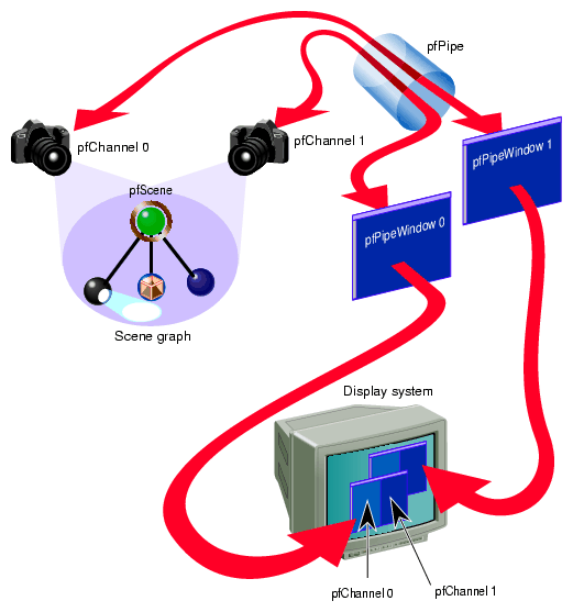
A pfPipe can display one or more channels in one or more windows, as shown in Figure 5-1. Each pfChannel in a window corresponds to a viewport.
This chapter discusses, in the following sections, many of the important classes that constitute the process of taking data from a scene graph database and rendering it on a display system:
To use a pfChannel:
“Creating and Configuring a pfPipeWindow ”. (Optional)
“Configuring a Viewport for the pfChannel”. (Optional)
“Defining the Viewing Frustum”.

Note: Steps 4, 5, and 6 can be completed in any order.
The following sections explain this procedure.
A pfPipe is a graphics pipeline that renders one or more pfChannels into one or more pfPipeWindows, as shown in Figure 5-1.
The pfPipe is the software abstraction of the hardware graphics pipeline. You can create as many pfPipe objects as you like. For optimal performance, use only one pfPipe object per hardware graphics pipeline.
To acquire a handle to a pfPipe object, use the following pfPipe method:
pfPipe *pipe = pfGetPipe(0); |
To create a pfChannel, use the following constructor:
pfChannel *channel = new pfNewChan(pipe); |
where pipe is a pointer to a pfPipe.
The pfChannel is automatically associated with the first pfPipeWindow in the pfPipe. If a pfPipeWindow is not explicitly created, one is generated automatically and set to be fully screened.
To create and configure a pfPipeWindow in which the pfPipe displays its rendering, use the following method:
pfPipeWindow* pfNewPWin(pfPipe *pipe); |
where pipe is a pointer to a pfPipe.
Use the pfPipeWindow methods to configure a pfPipeWindow.
To attach a scene to the pfChannel, use the following method:
void pfChanScene(pfChannel *chan, pfScene *scene); |
where chan and scene are the pfChannel to a scene to connect.
The viewport is that portion of the pfWindow in which the pfChannel is displayed, as shown in Figure 5-1. If you do not configure the viewport, the pfChannel defaults to displaying in the entire pfWindow.
You can create and modify the viewport of a pfChannel using the following line of code:
void pfChanViewport(pfChannel *chan, float left, float right,
    float bottom, float top);
|
chan is the pfChannel associated with the viewport.
left and right specify the X coordinates from the left side to the right side of the viewport. Values are clamped between 0.0 and 1.0, where 1.0 is the entire width of the pfWindow.
bottom and top specify the Y coordinates from the bottom to the top of the viewport. Values are clamped between 0.0 and 1.0, where 1.0 is the entire height of the pfWindow.
pfEarthSky objects draw sky, horizon, and ground in different weather conditions.
To display the background, follow these steps:
Use pfClear to clear the buffers in the current graphics window.
Use pfNewESky to create a new pfEarthSky object.
Use pfChannel::pfChanESky() to attach the pfEarthSky to a pfChannel.
pfEarthSky is called automatically in the DRAW process, unless a DRAW callback is present, in which case it must be explicitly called using pfClearChan.
You might like to start the size of the view frustrum so that the shape in it is completely in view. To determine the size of a shape, you retrieve the bounding sphere for the shape. The bounding sphere is a sphere that encloses a shape and approximates its size, as shown in Figure 5-2.
To return the size of a bounding sphere, use the following method:
int pfGetNodeBSphere( pfNode *node, pfSphere *sphere); |
This method returns the bounding sphere, sphere, for the node, node. The bounding sphere is returned as a pfSphere, defined as:
typedef struct {
    pfVec3 center;
    float radius;
} pfSphere;
|
| Note: The bounding spheres are often slightly larger than the size of the geometry. |
Use the dimensions of the bounding sphere as a guideline for the starting size of the view frustum, for example:
pfGetNodeBSphere(shapeNode, &Bsphere);
distanceToShape = 2.0f * Bsphere.radius;
pfChanNearFar(chan, 1.0f, 10.0f * Bsphere.radius);

float sceneSize = 2*bsphere.radius;

    /* Set initial view to be “in front” of scene */
    /* first put view point at center of sphere */
    PFCOPY_VEC3(Shared->view.xyz, bsphere.center);

    /* then back up so all is visible */
    Shared->view.xyz[PF_Y] -=      sceneSize;
    Shared->view.xyz[PF_Z] += 0.25f*sceneSize;

    /* look up the Y axis */
    pfSetVec3(Shared->view.hpr, 0.0f, 0.0f, 0.0f);

    pfChanView(chan, Shared->view.xyz, Shared->view.hpr);
|
The following geometries are used as bounding volumes for the following classes:
pfSpheres are used as bounding volumes for pfNodes.
pfBoxes are used as bounding volumes for pfGeoSets.
pfCylinders are used as bounding volumes for intersection rays.
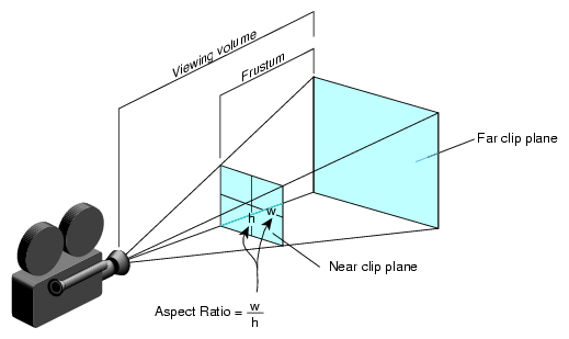
The viewing frustum is defined by the following:
These parameters are shown in Figure 5-3.
The following sections explain how to set these parameters.
To set up the viewing frustum, use the following method:
void pfChanNearFar( pfChannel *chan, float near, float far); |
chan is the pfChannel, near and far define the distances to the near and far clipping planes of the viewing frustum.
Shapes closer to the camera than the near clip plane or further than the far clip plane are not rendered. The default values for each clip plane are:
Near clip plane = 1.0
Far clip plane = 1000.0
The near clip plane must lie between 0.0 and the far clip plane.
| Tip: Moving the near clip plane close to the origin degrades Z-buffer precision. |
To set up the height and width of viewing frustum, use the following method:
void pfChanFOV( pfChannel *chan, float horiz, float vert); |
where chan is the pfChannel and horiz and vert, expressed in degrees, define the horizontal and vertical dimensions, respectively, of the view frustum, as shown in Figure 5-3. The default values are:
horiz = 45.0
vert = 0.0
If one angle is less than or equal to 0.0 degrees, that dimension is computed using the other angle and the viewport aspect ratio. Generally, you should only specify one of the angles so that the other is determined automatically to fit into viewport without distortion.
To set up the direction and position of the viewing frustum, use the following method:
void pfChanView( pfChannel *chan, pfVec3 xyz, pfVec3 hpr); |
where
chan is the pfChannel.
xyz is the position of the camera in world space coordinates.
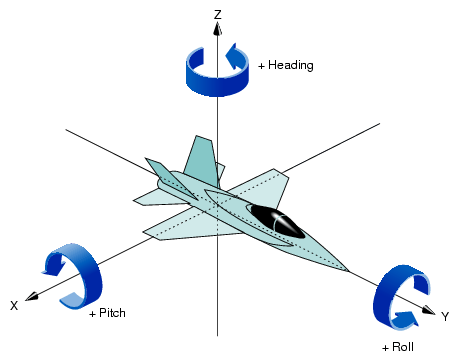
hpr is the heading, pitch, and roll of the camera, specified in degrees.
The heading, pitch, and roll values account for the rotation of the camera in any of the three dimensions, as shown in Figure 5-4.
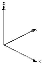
The starting hpr is oriented at the origin looking down the Y-axis.
OpenGL Performer also includes a pfCoord data type that defines the location and the rotation values.
typedef float pfVec3[3];

typedef struct (
    pfVec3 xyz;
    pfVec3 hpr;
}pfCoord;
|
| Note: The multiplication order is roll, pitch, and then heading. |
CULL and DRAW traversals are executed for each channel on a pfPipe whenever you call pfFrame. If you want to modify the default behavior when pfFrame is called on a channel, you can use callback functions.
For example, if you have special knowledge that the default CULL process cannot know, customize the behavior of the channel when CULL traverses the channel. One example is if you know you are inside a house, you would cull everything outside the house. The default CULL process would not necessarily produce this result.
To set up a channel callback function, use the following method:
void pfChanTravFunc(pfChannel* chan, int trav, pfChanFuncType func); |
chan is the channel for which you are setting up the callback function.
trav is the kind of traversal that triggers the callback function. Possible values include:
PFTRAV_CULL
PFTRAV_DRAW
func is the callback function called when the specified traversal, trav, evaluates the channel, chan.
The default behavior is to call:
pfCull from the CULL callback
pfClearChan and pfDraw from the DRAW callback
You can either ignore or add to this behavior.
The data derived from a channel traversal callback function must be sent down the graphics pipeline at frame boundaries. To synchronize the use of channel callback data, follow these steps:
Allocate memory and associate it with a channel.
Mark the data in the allocated memory as ready to be passed down the graphics pipeline at the next pfFrame call.
The following methods accomplish those tasks:
void * pfAllocChanData(pfChannel* chan, int size); void pfPassChanData(pfChannel* chan); |
size is the number of bytes of memory to allocate and associate with the channel, chan.
Changes are passed down the graphics pipeline only. For example, changes in the CULL process are not seen in the APP process.
Example 5-1 shows how to implement channel callbacks using pass through data. The example assumes that the CULL and DRAW callbacks have already been set up.
Example 5-1. Channel Callback Using Passthrough Data
typedef struct {
    int frameCount;
} PassData;

PassData *data = (PassData *)pfAllocChanData(chan, sizeof(PassData));
...
while (...) {
    data->frameCount = pfSync();
    pfPassChan Data(chan);
    pfFrame();
}

void cullChan(pfShannel *chan, void *data)
{
    // Changes made to data will be seen in channel DRAW callback.

    PassData *pass = (PassData *)data;
    pass->frameCount++;
    ...
}
|
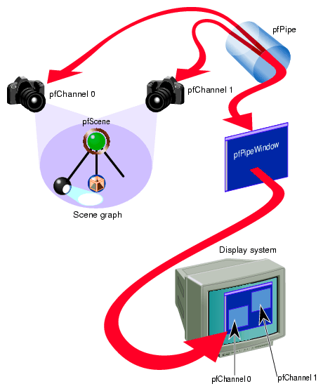
Multiple channels can be connected to a single pfPipe; a single pfChannel, however, cannot be connected to more than one pfPipe. pfPipe maintains a list of channels attached to it.
Each pfChannel is rendered in its own viewport, as shown in Figure 5-5.
In Figure 5-5, pfChannel 0 is rendered in viewport 0, and pfChannel 1 is rendered in viewport 1. The channels are rendered in the order they are created.
For information about rendering channels in their own viewport, see “Configuring a Viewport for the pfChannel”.
At times you may want to have different views of the same part of the scene. For example, each pfChannel might show the same scene at different LOD levels. These two views of the same scene require that the channels showing each view have the same attributes.
OpenGL Performer makes it easy for different channels to share attributes by creating pfChannel groups. One pfChannel is chosen as the master pfChannel and the other channels in the group are attached to the master, as follows:
int pfAttachChan(pfChannel *master, pfChannel *chan); |
master is the pfChannel whose attributes are used for all channels attached to it. chan is a different pfChannel that is dependent upon the master pfChannel; chan uses the master pfChannel's attributes.
You can add as many channels to the group as you like by repeating the pfAttachChan() method.
By default, the channels in a group use the master pfChannel's attributes except for:
Viewport
View offsets, explained in “Using View Offsets”
Hardware swap buffers signal (for multichassis sync)
You can, however, specify other attributes that you do not want a pfChannel to derive from the master by setting the bits in a mask. By default, all of the bits in the mask are ON. To unshare attributes, follow these steps:
Get the pfChannel's mask, using:
uint pfGetChanShare(pfChannel *chan);
Unset the bit for the attribute you do not want to be shared with the master pfChannel.
Set the mask, using:
void pfChanShare(pfChannel *chan, uint mask);
The following code segment shows an implementation of this procedure in which the attribute, near and far planes, is unset.
mask = pfGetChanShare(chan); mask &= !PFCHAN_NEARFAR; pfChanShare(chan, mask); |
In this example, the view frustum of the pfChannel may be different from that of the master pfChannel.
Table 5-1 lists the pfChannel attributes that can be shared.
Table 5-1. pfChannel Attributes
pfChannel property | Description |
|---|---|
PFCHAN_FOV | Field of view angles |
PFCHAN_NEARFAR | Near and far clip planes |
PFCHAN_VIEW | View position |
PFCHAN_VIEW_OFFSETS | xyz, hpr offsets from master viewpoint |
PFCHAN_VIEWPORT | Viewport |
PFCHAN_SCENE | Scene |
PFCHAN_EARTHSKY | Earth-sky model |
PFCHAN_STRESS | Stress filter parameters |
PFCHAN_LOD | Level of detail modifiers |
PFCHAN_SWAPBUFFERS | Signal to swap |
PFCHAN_SWAPBUFFERS_HW | Signal to swap (multipipe) |
PFCHAN_STATS_DRAWMODE | Statistics graph characteristics |
PFCHAN_APPFUNC | Application callback |
PFCHAN_CULLFUNC | CULL callback |
PFCHAN_DRAWFUNC | DRAW callback |
Although a pfChannel might look at the same scene as that seen by the master pfChannel, you might like to orient the pfChannel differently. For example, you might like the master pfChannel to show one view of a scene and a slave pfChannel to show a view of adjacent scenery so that when the two channels are projected side by side, you have a wide view of the scene.
The view offset can be set for each pfChannel. If it is not set, the offset is zero, which means the master and slave channels are in the same location and orientation.
To specify how a slave's pfChannel view is different from the master pfChannel View, use the following method:
void pfChanViewOffsets(pfChannel* chan, pfVec3 xyz, pfVec3 hpr); |
chan specifies the pfChannel to offset.
xyz specifies the 3D coordinates, relative to the master pfChannel, where the slave pfChannel is located.
hpr specifies the rotation of the pfChannel, relative to the master pfChannel, where h, p, and r are the degrees of rotation about the x, y, and z axes, respectively.
For example, if you want the slave pfChannel to be 100 units above the master pfChannel pointed down, the values for x, y, and z would be (0, 0, 100) and the values for h, p, and r would be (0, -90, 0).
The Z-axis is oriented vertically to the ground, as shown in Figure 5-6.
The starting orientation is located at the origin and pointed down the Y-axis.
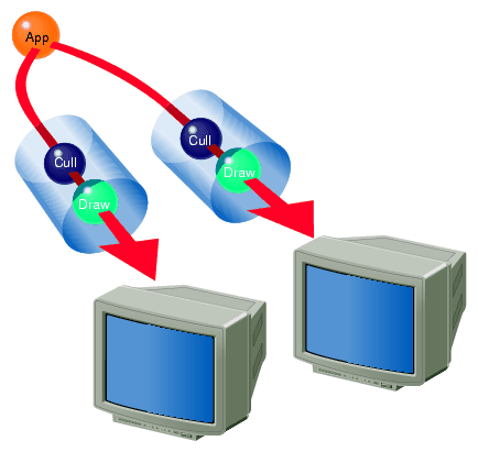
You may find it appropriate to display your data over more than one display system. For example, you might want to present the left side and right side of a scene on two different monitors. The CULL and DRAW stages are specific to each pfPipe object; the APP stage, however, is shared by both pfPipe objects, as shown in Figure 5-7.
pfMultiprocess controls the multiprocessing configuration of a pfPipe. The CULL and DRAW stages can run as a single process or, for improved performance, run as separate processes, according to the value passed to pfMultiprocess. For example, to run the APP, CULL and DRAW stages as separate processes, use the following line of code:
pfMultiprocess(PFMP_APP_CULL_DRAW); |
You must call pfMultiprocess between pfInit and pfConfig. If you do not, OpenGL Performer creates a multiprocessing configuration automatically based on the number of CPUs in the run-time hardware.
For more information about multiprocessing, see Chapter 11, “Multiprocessing”.
To create multiple pfPipe objects, use the following pfPipe method:
void pfMultipipe(int npipes); |
npipes is the number of pfPipe objects to create.
Call pfMultipipe between pfInit and pfConfig. By default, there is just one pfPipe.
For more information about multiprocessing, see Chapter 11, “Multiprocessing”.
