This chapter describes the basic classes that implement the database- to- display pipeline in the following sections:
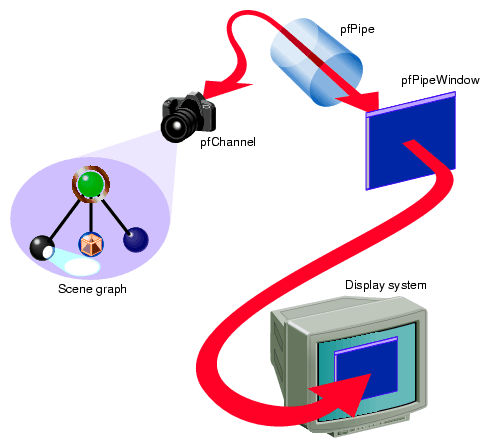
A description of your world is encapsulated in the scene graph, and a view into the world is described by a pfChannel. This view is rendered by an OpenGL Performer software pipeline, pfPipe, into a window, pfPipeWindow, on a selected screen. This path of operation and associated classes is shown in Figure 4-1.
A scene graph is a directional, acyclic graph (DAG). Its structure determines the order of operation of its data.
pfNode is the base class of all scene graph node types. A node might hold, for example, the data for a geometry. Different node types provide mechanisms for grouping, animation, level of detail, and other concepts that are applied when the scene graph is traversed with a traverser.
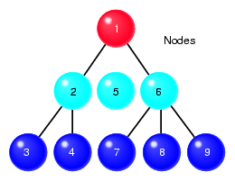
The nodes in a scene graph are arranged in a hierarchy, as shown in Figure 4-2.
The hierarchy of nodes can have many meanings, for example:
The child nodes may be part of the parent node. For example, the parent node might encapsulate a light bulb, where one child node encapsulates the silver base of the light bulb, and another child node encapsulates the glass part of the light bulb.
The parent node may also just serve as a means of grouping the children nodes. For example, four children might encapsulate data that renders four tires on a car.
The children nodes can all be views of the same geometry at different levels of resolution.
The parent node, in this example, switches the source of the display data between its child nodes according to, for example, how far the geometry is from the viewer. The bottom of the group contains geometry that is stored in several childless leaf nodes, such as pfGeode.
The entire scene graph represents all of the data in the database.
Nodes in a scene graph can respond to some kind of traversal. A traverser runs over part or all of the hierarchy of nodes in the scene graph, which triggers some response. Not all nodes, however, respond to all traversals.
Examples of traversers include the CULL traverser, pfCull, and the DRAW traverser, pfDraw. pfNodes can use the OpenGL Performer default behavior, or define their own using callback mechanisms. For more information about callbacks, see “Customizing OpenGL Performer Traversals” in Chapter 6.
The hierarchy of the scene graph specifies the order in which the nodes are processed by a traversal. The order is top down. For example, the numbers on the nodes in Figure 4-2 show one example of the order in which the traversal is applied to each node.
A traversal going from one node to another is said to traverse the scene graph. Figure 4-2 shows that the traversal was applied at the root node, pfScene, of the scene graph. A traversal applied at the root is passed throughout the entire scene graph. You can, however, apply the traversal to a subsection of the scene graph by applying it to any node beside the root node.
For more information about scene graphs, see Chapter 6, “Creating Scene Graphs”.
A channel is equivalent to a camera moving throughout the scene. Whereas the scene graph encapsulates all of the visual data in the scene, the channel contains only that visual information that is visible to the viewer; the channel shows a slice of the scene from a specified perspective. The view culled by the channel is defined by:
Camera position and orientation
Viewing frustum
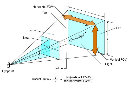
The channel provides a particular view of a scene, as shown in Figure 4-3.
| Note: OpenGL Performer allows you to create asymmetric frustums. |
The viewing volume is the pyramid shown in Figure 4-3. The frustum is the truncated pyramid defined by:
Near and far clipping planes.
Horizontal and vertical fields of view.
The only geometries in view are those in the viewing frustum. Geometries in the scene graph are invisible when they are:
Beyond the far clipping plane.
Between the viewer and the near clipping plane.
Outside the horizontal and vertical fields of view.
Each channel is associated with a scene graph; however, one scene graph may be associated with more than one channel.
For more information about channels, see Chapter 5, “Creating a Display with pfChannel”.
The pipe renders the visual data in the viewing frustum to a window. The pipe is the software abstraction of the hardware graphics pipeline.
Rendering the scene occurs in three stages:
APP—updates the location and look of geometries and updates the viewing location and orientation.
CULL—determines which geometries in the scene are visible (in the viewing frustum), taking occlusion into account.
DRAW—renders all visible geometries.
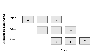
Each stage is potentially a separate process. For maximum performance, run each of these processes on a different CPU. When using three CPUs, OpenGL Performer can process three frames at the same time, as shown in Figure 4-4.
Figure 4-4 shows how:
Three frames are processed sequentially across three processes.
The three processes running on three CPUs can process up to three frames of data concurrently, while the APP stage processes the third frame, the CULL stage processes the second frame, and the DRAW stage processes the second frame.
Most of your work is done in the APP stage, which updates the location of the geometries and the camera in the scene.
It is possible to customize the CULL and DRAW stages using callback functions. It is more common, however, to let OpenGL Performer handle those stages. For more information about customizing stages using callback functions, see “Customizing OpenGL Performer Traversals” in Chapter 6.
Each stage runs as a separate traversal over the scene graph. Table 4-1 shows the classes that start each stage.
Table 4-1. Traversals Launched
Traversal | Launched By |
|---|---|
APP | pfApp (from pfSync) |
CULL | pfCull (from pfFrame) |
DRAW | pfDraw (from pfFrame) |
ISECT | pfNodeIsectSegs/pfChanNodeIsectSegs |
The ISECT traversal searches for intersections. For more information, see Chapter 13, “Intersection Testing”.
When you call pfFrame, the CULL traversal generates a libpr display list of geometry and state commands, which describes the scene that is visible from a pfChannel.
The DRAW traversal traverses the display list and sends commands to the Geometry Pipeline to generate the scene.
The libpr display list keeps pointers to user data. The list allows users to have dynamic data.
Traversing a pfDispList is much faster than traversing the database hierarchy because the pfDispList flattens the hierarchy into a simple, efficient structure. In this way, the CULL traversal removes much of the processing burden from the DRAW traversal; throughput greatly increases when both traversals are running in parallel.
libpr supports display lists, which contain and later execute libpr graphics commands. pfNewDList() creates and returns a handle to a new pfDispList. You can select a pfDispList as the current display list with pfOpenDList(), which puts the system in display list mode. Any subsequent libpr graphics commands, such as pfTransparency(), pfApplyTex(), or pfDrawGSet(), are added to the current display list. Commands are added until pfCloseDList() returns the system to immediate mode. In display list mode, changes to the scene do not take effect until the next pfFrame is called.
It is not legal to have multiple pfDispLists open at the same time, but a pfDispList may be reopened, in which case commands are appended to the end of the list.
Once a display list is constructed, it can be executed by calling pfDrawDList(), which traverses the list and sends commands down the Geometry Pipeline. pfFrame, however, executes the display list automatically.
For more information on pfDispList, see the OpenGL Performer Programmer's Guide .
The basic parts of your OpenGL Performer program include:
Initializing OpenGL Performer.
Acquiring a pipe.
Creating a channel and window.
Associating the channel with the appropriate window.
Loading the scene graph and associate it with the channel.
Positioning the channel(s) and updating the scene.
Calling pfFrame to draw the scene.
Creating the simulation loop to return to step 6.
To initialize OpenGL Performer, use the following call:
void pfInit(void); |
Initializing OpenGL Performer causes the following:
Sets up the shared memory arena for the three processes.
Initializes the OpenGL Performer graphics state.
pfInit() must be the first method called in an OpenGL Performer application. pfConfig creates the additional, desired OpenGL Performer processes. You clean up by calling pfExit(), which exits the application and kills all OpenGL Performer processes.
Because all three processes can work on the same frame of visual data, a shared memory arena is required. OpenGL Performer uses shared memory arenas that can be accessed by separate processes. All OpenGL Performer processes need to access the scene graph, so all scene graph data must be in the shared memory arena. OpenGL Performer creates the arena for you in pfInit in a libpf application.
pfNodes and other libpf objects are automatically created in the shared memory arena. You can get the shared arena with pfGetSharedArena.
For more information about shared memory, see Chapter 19, “Performance Tuning and Debugging” , in the OpenGL Performer Programmer's Guide.
To create the pipe, channel, and pipe window, use the following calls:
// pfConfig must go first pfConfig(); // Acquire handled pipe number 0. pfPipe *pipe = pfGetPipe(0); // Create the pipe window and associate it with the pipe. pfPipeWindow *pwin0 = pfNewPWin(pipe); // Create the channel and associate it with the pipe. pfChannel *chan0 = pfNewChan(pipe); // Associate the channel and pipe window so the channel is drawn in it. pfAddChan(pwin0, chan0); // Calls that cause the window to be opened at next pfFrame() pfOpenPWin(pwin0); pfFrame(); |
These methods configure the graphics pipeline, and fork all requested processes, including APP, CULL, and DRAW.
To specify the path to the scene graph file, use the following method:
void pfFilePath(const char *pathName); |
pathName is the complete path to the scene graph file. For more information about loading a scene graph, see “Loading a Scene Graph” in Chapter 6.
Use the following methods to position the channel:
void pfChanFOV(pfChannel* chan, float horiz, float vert); void pfChanNearFar(pfChannel* chan, float near, float far); |
The simulation loop, up to this point, has handled the APP process. To start the CULL and DRAW processes, use the following call:
void pfFrame(void); |
Besides starting the CULL and DRAW processes, this call, along with pfSync, handles frame synchronization.
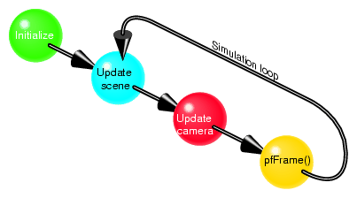
The simulation loop drives the application. Its actions are carried out in the APP process. The simulation loop repeats endlessly until the application exits.
Figure 4-5 shows that the simulation loop generally has three steps:
Update the appearance, shape, and location of the objects in the scene.
Update the position and orientation of the camera in the scene.
Redraw the scene.
Example 4-1 shows pseudo code for a synchronization loop.
Example 4-1. Synchronization Loop
while(!finished)
{
    handleinput();
    updateScene();
    anyCriticalUpdate();
    pfFrame();
}
|
Performer applications are interactive and use the OpenGL/X Window System on IRIX and Linux systems.
User input devices are unlimited, but OpenGL Performer provides utilities for handling the following:
Keyboard
Mouse
Track ball
Flybox
Other input can come from the following:
Network
Reflective memory
To implement user input, you need to:
Initialize the utility library.
Set the window type.
Enable user input on the window.
Collect the window events in a forked process.
The utility library, libpfutil, provides input handling utilities. Initialize it by using the following call:
void pfuInitUtil(void); |
Clean it up by using the following call:
void pfuExitUtil(); |
To enable user input, you can use the following method:
void pfuInitInput( *pwin, int mode); |
where pwin points to the pfPipeWindow where the user enters information, and mode is one of two tokens:
PFUINPUT_X
PFUINPUT_X_NOFORK
You can set the window with the following method:
void pfPWinType( pwin, type); |
where pwin points to the pfPipeWindow where the user enters information and type is one of the following tokens:
PFPWIN_TYPE_X
PFPWIN_TYPE_X_NOFORK

Note: On Windows, the user events are not processed in a separate process. Hence, use PFUINPUT_X_NOFORK and PFPWIN_TYPE_X_NOFORK.
To clean up when user input is finished, use the following method:
pfuExitInput(); |
OpenGL Performer provides utilities for asynchronously calculating window system events and returning them to the application. User events are stored in a pfuEventStream object, which is a queue. To retrieve keyboard and mouse events, use the following methods, respectively:
pfuGetEvents (event); pfuGetMouse(mouse); |
where event and mouse are pointers to keyboard events and a pfuMouse structure, respectively.
To complete the implementation, you must respond to the following events:
Examine the keyboard input and take appropriate actions.
Use pfiXformer to handle the mouse events.
OpenGL Performer provides a routine for examining keyboard input. You only need to add code that takes appropriate actions in response to the input, as shown in Example 4-2.
Example 4-2. Handling Keyboard Input
void handleEvents(void)
(

    extern pfuEventStream events;
    pfuEventStream *pEvents = &events;

    // get events and number of events pfuGetEvents(&events);
    numDevs = pEvents->numDevs;

    // process each of the events; dev is the kind of event, val is
    // its value, such as a keyboard event with an ASCii value of 27.
    for ( j=0; j = numDevs; ++j) (
        dev = pEvents->devQ[j];
        val = pEvents->devVal[j];

        if ( pEvents->devCount[dev] > 0) {
            switch ( dev ) {
            ...

            // process keyboard input
            case PFUDEV_KEYBD:
                for ( i=0; i < pEvents->numKeys; ++i ) {
                key = pEvents->keyQ[i];
                if ( pEvents->keyCount[ key ] ) {

                    switch [key ] {

                    case 27:
                    // escape key; exit program
                    exitFlag = 1; break;

                    case `h':
                    // print help
                    printHelp(progName);
                    break; ...
|
