This chapter describes the brick connectors that are used to cable the bricks together and provides cabling examples in the following sections:
-

Warning: The cabling examples in this chapter are shown to you only for your understanding of how the bricks in your system are cabled together. For your safety and for the protection of your server system, only your SGI system support engineer (SSE) can cable together the bricks in your SGI Origin 3000 series server system.
With the exception of the D–brick, all the SGI Origin 3000 series server systems bricks are cabled together with NUMAlink cables.
| Note: The D–brick is cabled to the server through the cabling of its Gigabit Interface Connector (GBIC) port to a host bus adapter (HBA) PCI card in an I–brick or P–brick on your server. For more details about this connection, see the GBIC port description under “FC-AL Loop Resiliency Circuit (LRC) I/O Modules” in Chapter 8. |
This section describes and illustrates the brick connectors that are used to cable the bricks together in an SGI Origin 3000 series server system. This sections describes the connectors for the C–brick, I–brick, P–brick, X–brick, and R–brick.
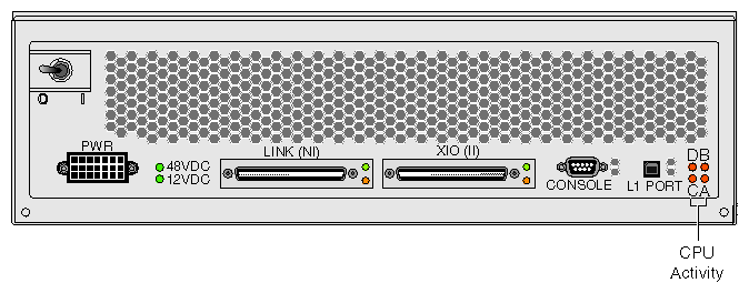
The following C–brick connectors shown in Figure 12-1 are used to connect the C–brick to other bricks in the SGI Origin 3000 series server system:
LINK (NI - Network Interface) connector. This connector connects the C–brick to an R–brick or to another C–brick if the system does not have an R–brick, such the SGI Origin 3200 server. This connection is made with a NUMAlink 3 cable at 1.6 GB/sec in each direction.
The LINK connector LEDs light yellow when connector is cabled securely to an R–brick. LEDs light green when connection is negotiated with device with which connector is cabled.
XIO (II - I/O Interface) connector. This connector connects a C–brick to an I/O–brick (I–brick, P–brick, or X–brick); this connection occurs via a NUMAlink 3 cable at 1.2 GB/sec in each direction.
The XIO connector LEDs light yellow when connector is cabled securely to an I/O device. LEDs light green when connection is negotiated with device with which connector is cabled.
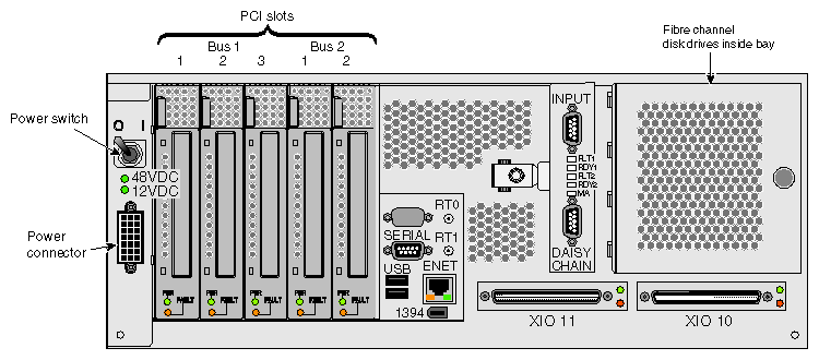
Figure 12-2 shows the following I–brick connectors (and LEDs) used to connect the I–brick to C–bricks in the SGI Origin 3000 series server system:
XIO 11 and XIO 10 connectors. Each of these connectors can connect the I–brick to a C–brick. As an option, the second connector can be connected to another C–brick to create a dual-ported I–brick, which would provide greater bandwidth.
XIO 11 and XIO 10 connector LEDs. Light yellow when the connector is cabled securely to the C–brick device, and light green when the connection is negotiated with the C–brick device with which the connector is cabled.
Figure 12-3 shows the following P–brick connectors (and LEDs) used to connect the P–brick to C–bricks in the SGI Origin 3000 series server system:
XIO 10 and XIO 11 connectors. These connectors connect the P–brick to a C–brick. As an option, the second connector can be connected to another C–brick to create a dual-ported P–brick, which would provide greater bandwidth.
XIO 10 and XIO 11 connector LEDs. Light yellow when the connector is cabled securely to the C–brick device. Light green when the connection is negotiated with the device with which the connector is cabled.
Figure 12-4 shows the following X–brick connectors (and LEDs) used to connect the X–brick to C–bricks in the SGI Origin 3000 series server system:
XIO 11 and XIO 10 connectors. These connectors connect the X–brick to a C–brick. Only one connector is required to connect to a single C–brick. As an option, the second connector can be connected to another C–brick to create a dual-ported X–brick, which would provide greater bandwidth.
XIO 11 and XIO 10 connector LEDs. LEDs light yellow when the connector is cabled securely to the C–brick device, and light green when the connection is negotiated with the device with which the connector is cabled.
Figure 12-5 shows the following R–brick connectors (and LEDs) used to connect the R–brick to other bricks in the SGI Origin 3000 series server system:
Links R TO R (1, 6, 7, and 8 or A, F, G, and H). These link connectors connect the R–brick to other R–bricks in the server system.
Link connector LEDs. All the link connectors (1 through 8) have two LEDs (one that lights green and another that lights yellow):
The green LED (the hardware LED) lights to indicate that a cable is connected properly between the R–brick and another brick.
The yellow LED (the software LED) lights to indicate that packets are being transferred successfully across the link.
Links R TO R and C TO R (2, 3, 4, and 5 or B, C, D, and E). These link connectors connect the R–brick to C–bricks.

Note: Links 2, 3, 4, and 5 are also used in the metarouter to connect other routers in server configurations greater than 128 processors. Besides link signals, links 2, 3, 4, and 5 carry system controller USB signals, which are distributed over the network cables. Since the C–bricks require USB signals, the C–bricks are cabled only to ports 2, 3, 4, and 5.
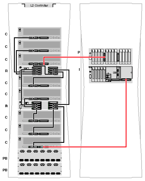
If the SGI Origin 3400 server system has more than four C–bricks, C–bricks are cabled to a second R–brick as shown in Figure 9-3. These C–bricks communicate with the first four C–bricks through a connection between the R–bricks. R–brick to R–brick links use ports 1, 6, 7, and 8 located on the top half of the R–brick panel and labeled LINKS R TO R.
In the case of a server configuration greater than 128 processors, the metarouters would use links 1, 6, 7, and 8 in addition to Links 2, 3, 4, and 5, which are normally used to connect directly to C–bricks.
This section shows cabling examples for the SGI Origin 3200, SGI Origin 3400, and SGI 3800 server systems.
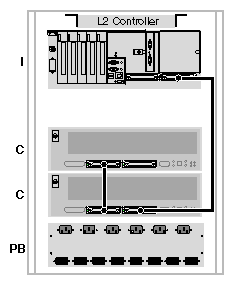
Figure 12-7 shows an example of the cabling together with NUMAlink cables of the bricks in an SGI Origin 3200 server:
Figure 12-8 shows an example of the cabling together of the bricks in an SGI Origin 3400 server:
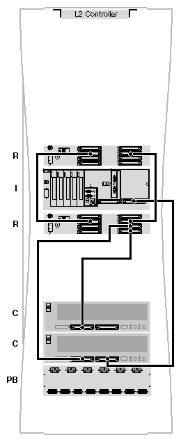
Figure 12-9 shows an example of the cabling together of the bricks in an SGI Origin 3800 server:
