This chapter describes the L1 controller and L2 controller used to monitor, manage, and control your SGI Onyx 3000 series graphics system in the following sections:
System Controllers in the SGI Onyx 3000 series graphics system are generally used for the following overall tasks:
Manage power control and sequencing
Provide environmental control and monitoring
Initiate system resets
Store identification and configuration information
Provide console/diagnostic and scan interface
The graphics system has two controllers to monitor and manage the graphics system:
L1 controller. This is a brick-level controller used to monitor and control brick functions such as fan speed (for temperature control) and voltage levels.
L2 controller. This is a rack-level controller that enables remote maintenance, controls resource sharing, controls the L1 controllers in the system, and maintains controller configuration and topology information between itself and other L2 controllers. The L2 controller (optional in the SGI Onyx 3200 graphics system that is housed in a short rack) is standard in all the system tall racks containing C–bricks.
You can enter L1 and L2 controller commands to reconfigure your L1 and L2 controllers to modify the management and control of your SGI Onyx 3000 series graphics system to suit your needs. The L1 and L2 controller commands are entered at a system console connected to the L2 controller console port.
| Note: For instructions to connect a system console to your SGI Onyx 3000 series graphics system, for a listing and description of the L1 and L2 controller commands, and for a detailed description of the L1 and L2 controllers, see the SGI Origin 3000 Series Owner's Guide. |
The G–brick, V–brick, and N–brick, like all bricks in the SGI Onyx 3000 series graphics system (except the D–brick), have built–in L1 controllers to monitor many functions of the brick. (For more details about the L1 controller and the L1 controller for other bricks in your graphics system, see SGI Origin 3000 Series Owner's Guide.)
| Note: The D-brick, which does not have built-in L1 system controller, has instead its own ESI/Ops panel module with a microcontroller for monitoring and controlling all elements of the D–brick. See the D–brick chapter in SGI Origin 3000 Series Owner's Guide for details. |
Some of the functions monitored by the L1 controller are common to all the system bricks and some are specific to a brick type. Basic functions of the L1 controller are listed in Table 6-1.
Table 6-1. Basic L1 Controller Functions
L1 Function | Used in G-brick? | Used in V–brick? | Used in N–brick? |
|---|---|---|---|
Controls voltage regulator modules (VRMs). | No | Yes | Yes |
Monitors voltage and reports increases, decreases, or failures in voltage levels. | Yes | Yes | Yes |
Controls voltage margining within the brick. | No | Yes | Yes |
Controls and monitors fan speed. | Yes | Yes | Yes |
Monitors and reports operating temperature and status of 48 VDC input power. | No | Yes | Yes |
Monitors and controls LEDs. | Yes | Yes | Yes |
Reads system identification (ID) PROMs. | No | Yes | Yes |
Monitors the reset switch and the nonmaskable interrupt (NMI) switch. | No | Yes | Yes |
Monitors the On/Off power switch. | Yes | Yes | Yes |
The L1 controller hardware used with the G-brick, V–brick, and N–brick consist of the following:
Logic components:
SRAM, NVRAM, and flash memory
Microcontroller unit (MCU)
Inter-integrated circuit bus (I2C bus)
ID EEPROM
Front panel connection cable
Front panel display
Voltage regulator module (VRM)
USB port
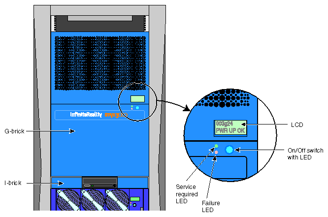
The front panel display of the G–brick L1 controller (as shown in Figure 6-1), like the L1 controller for the V–brick and N–brick, consists of a 2-line, 12-character liquid crystal display (LCD) that provides:
Brick identification
System status
Warning of required service or failure
Identification of failed components
On/Off switch

Note: For an illustration of a V–brick and an N–brick L1 controller display, see Chapter 2, “G–brick, V–brick, and N–brick”
In a single-rack configuration, the G-brick's L1 controller USB connection connects directly to an L2 controller L1 port (USB).
In a multirack graphics system with two or more G-bricks installed, the G-brick's L1 controller USB connection connects to a USB hub before connecting to the L2 controller.
The L1 controller on the V–brick and N–brick connect to the L2 controller via their connections to the C–brick, which is connected to the R–brick, which in turn is connected to one of the L2 controller L1 ports (USB).
The L1 controller display provides warnings, fault information, advisory status, and critical status messages. Note that as listed in Table 6-2, a voltage warning occurs when a supplied level of voltage is below or above the nominal (normal) voltage by 10%. A voltage fault occurs when a supplied level is below or above the nominal by 20%.
Table 6-2. L1 Controller Messages
Message | Meaning and Action Needed |
|---|---|
Internal voltage messages: |
|
ATTN: x.xV high fault limit reached @ x.xxV | 30-second power-off sequence for the brick (or system, if no backup is available). |
ATTN: x.xV low fault limit reached @ x.xxV | 30-second power-off sequence for the brick (or system, if no backup is available). |
ATTN: x.xV high warning limit reached @ x.xxV | Higher than nominal voltage condition is detected. |
ATTN: x.xV low warning limit reached @ x.xxV | Lower than nominal voltage condition is detected. |
ATTN: x.xV level stabilized @ x.xV | A monitored voltage level has returned to within acceptable limits. |
Fan messages: |
|
ATTN: locaFAN # x fault limit reached @ xx RPM | The L1 controller issues this fault message if a fan can not spin at its minimum RPM, and the environment is warm (greater than 30 ºC) or if there is another fan already spinning at its minimum RPM. A 30-second shutdown sequence starts. Check to see if a fan has failed. |
ATTN: FAN # x warning limit reached @ xx RPM | The L1 controller issues this fan warning when a fan is not spinning at its minimum RPM in a cool environment (less than 30 ºC). The system increases the fan RPM to provide additional air flow to compensate. Check to see if the fan stabilizes. |
ATTN: FAN # x stabilized @ xx RPM | Fan appears to be spinning at appropriate RPM. The L1 controller usually displays this message after a fan has been replaced. |
Temperature messages: low alt. |
|
ATTN: TEMP # advisory temperature reached @ xxC xxF | The ambient temperature at the brick's air inlet has exceeded 30 ºC. |
ATTN: TEMP # critical temperature reached @ xxC xxF | The ambient temperature at the brick's air inlet has exceeded 35 ºC. |
ATTN: TEMP # fault temperature reached @ xxC xxF | The ambient temperature at the brick's air inlet has exceeded 40 ºC. |
Temperature messages: high alt. |
|
ATTN: TEMP # advisory temperature reached @ xxC xxF | The ambient temperature at the brick's air inlet has exceeded 27 ºC. |
ATTN: TEMP # critical temperature reached @ xxC xxF | The ambient temperature at the brick's air inlet has exceeded 31 ºC. |
ATTN: TEMP # fault temperature reached @ xxC xxF | The ambient temperature at the brick's air inlet has exceeded 35 ºC. |
Temperature stable message: |
|
ATTN: TEMP # stabilized @ xxC/xxF | The ambient temperature at the brick's air inlet has returned to an acceptable level. |
Power off messages: |
|
Auto power down in xx seconds | The L1 controller has registered a fault and is shutting down. The message displays every five seconds until shut down. |
Brick appears to have been powered down | The L1 controller has registered a fault and has shut down. |
In the graphics-equipped rack, the L2 controller allows remote maintenance, controls resource sharing, manages the L1 controllers in the system, and maintains controller configuration and topology.
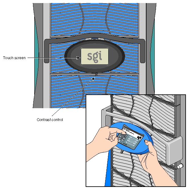
As a general rule, you would use the L2 controller touch display shown in Figure 6-2 in the following functional areas:
Powering the system on and off
Monitoring voltage margins
Resetting the system
Entering a non-maskable interrupt (NMI)
The L2 controller monitors and reports status information from the individual compute, I/O, and graphics bricks in the rack system. Information is displayed and commands can be selected using the L2 controller touch display on the front of the rack.
The following sections provide an overview of the L2 controller's features and functions. For more details about the L2 controller, see SGI Origin 3000 Series Owner's Guide.
The rack display is a 320 x 240 LCD touch display located on the front of the system, as shown in Figure 6-2. The L2 controller touch display translates what the user touches into commands. The controller displays the results of the commands.
The L2 controller performs the following functions:
Controls resource sharing.
Controls L1 controllers.
Resets the system.
Issues non-maskable interrupts (NMI).
Displays voltage margin information.
Routes data between upstream devices and downstream devices.
Upstream devices (for example, rack display, console, and modem) provide control for the system, initiate commands for the downstream devices, and act on the messages that they receive from downstream devices.
Downstream devices (for example, C-bricks, the USB hub of the R-brick, and L1 controllers of the bricks) perform the actions that are specified by the L2 controller commands, send responses to the L2 controller that indicate the status of the commands, and send error messages to the L2 controller.
Allows remote maintenance.
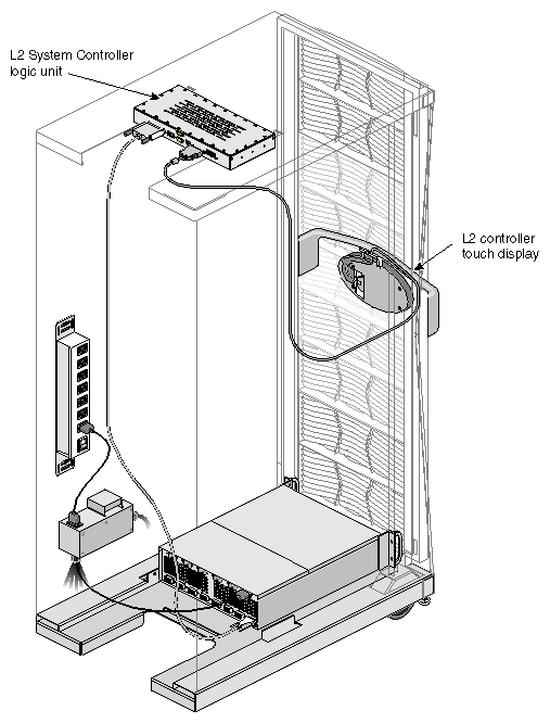
The L2 controller is mounted in the top of the rack. Figure 6-3 shows its location.
Input power is 48 VDC (about 30 W), which is provided by the power bay.
The L2 controller consists of rack display controllers, ports, and a software component, which are described in the following subsections.
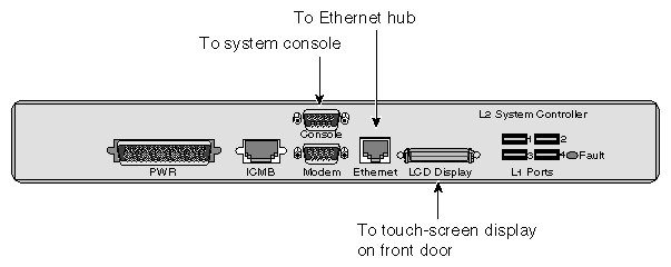
Figure 6-4 shows the connectors on the L2 controller.
The L2 controller contains a software component that transfers data from a send client to the appropriate receive client. The clients with which the L2 controller communicates are local to the L2 controller.
The software allows the router clients to:
Register with the router. (The software identifies the client with a unique ID.)
Register to receive messages from other clients (local or remote).
Receive commands and send corresponding responses.
Send commands and receive corresponding responses.
Receive messages that they are registered to receive.
The L2 controller logs the following information in separate files:
Messages and command responses from the L1 controllers (includes the I/O bricks).
Messages and output from the system console.
Debugging messages that the L2 controller produces.
Commands and responses from the L2 controller touch display.
Messages and output that are sent to the console (attached to the L2 controller).
Messages and output that are sent to the modem port (attached to the L2 controller).


