This chapter provides detailed descriptions of the G–brick, V–brick, and N–brick in the following sections:
The G–brick is a large 18U-sized brick that supports various combinations of InfiniteReality pipes (sets of boards) that with two pipes provides your SGI Onyx 3000 series graphics system with high-resolution graphics display capabilities for as many as 16 Silicon Graphics SuperWide monitors.
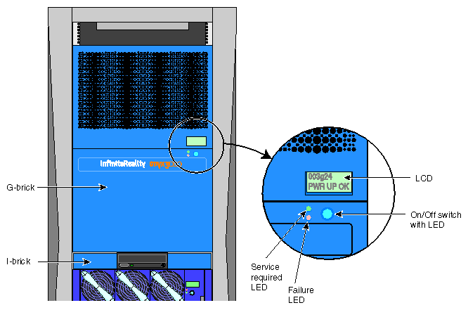
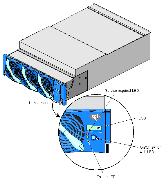
The following lists the G–brick internal components and front panel items. Figure 2-1 shows the G–brick's front panel items.
Internal components:
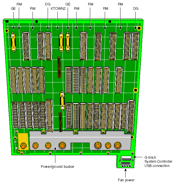
G–brick midplane. All graphics and interface boards connect to this midplane. (See Figure 2-5.)
Boards. The various boards (and daughterboards) that are supported and installed in the board slots in the rear panel of the G–brick are described in detail in “G–brick Rear Panel Items”.
Front panel items:
L1 controller display. This is a liquid crystal display (LCD) for the L1 controller.
On/Off switch with LED. Press this button to power on the G–brick internal components. Alternatively, you can power on the G–brick internal components at a system console. You can also power on the G–brick internal components at the L2 controller touch display.
L1 controller switches and LEDs:
On/Off switch LED. This LED lights green when the G–brick internal components are powered on and turns off when they are powered off.
Service required LED. This LED lights orange to indicate that an item is broken or not operating properly (for example, a fan is off), but that the G–brick is still operating.
Failure LED. This LED lights red to indicate that a system failure has occurred and the G–brick system is down.
Figure 2-2 shows the power switch, boards, connectors, and LEDs on the G–brick rear panel.
The G–brick rear panel has the following items:
Power switch. Move the power switch to the On (1) position to power on the G–brick L1 controller, and move it to the Off (0) position to power off the G–brick L1 controller. Powering on the L1 controller lights the 12 VDC (voltage direct current) LED green.
48 VDC and 12 VDC LEDs. When you move the power switch to the On (1) position, these LEDs light up. The 12 VDC lights green when the L1 controller is powered on and operating, and the 48 VDC lights green when the rest of the G–brick internal components are powered on and operating. Press the On/Off switch located on the L1 controller front panel to power on the internal components.
PWR (power) connector. This connects directly to a 220V power source (circumvents the power bay) to supply power to the G-brick.
11 board slots. These slots are used to install and replace a Ktown2 board and two InfiniteReality graphics pipes (sets of boards) in your graphics system. As you face the rear panel, the boards, as shown in Figure 2-3, are located as follows:
Six rightmost slots (pipe 0). These slots support a Geometry Engine (GE) board; one, two, or four Raster Manager (RM) board assemblies; and a Display Generator (DG) board.
Four leftmost slots (pipe 1). These slots support a GE board, one or two RM board assemblies, and a DG board.
Ktown2 board with two connectors. The top connector is used to connect pipe 0 (six rightmost slots) to an I/O brick connected to a C–brick. The bottom connector is used to connect pipe 1 (four leftmost slots) to an I/O brick connected to a C–brick.
LEDs.
PWR (power) and fault LEDs. The power LED lights green when an InfiniteReality card is installed correctly and is receiving power. The fault LED lights yellow when a fault occurs with the board.
Ktown2 board connector LEDs. These LEDs light yellow when the connector is cabled securely to the I/O brick device. They light green when the connection is negotiated with the I/O brick device with which the connector is cabled.
Figure 2-4 shows an example of a two-RM InfiniteReality graphics pipe board set that is supported by the rack's G-brick.
| Note: The 68-pin connectors on the RM assemblies are reserved for calligraphic lights; they are not for SCSI drives. |
The G-brick graphics module uses a midplane. All graphics and interface boards are placed in the rear of the module and connect to the back of the midplane. Figure 2-5 shows a view of the graphics midplane.
Various types of DG5 graphics boards are available to add graphics functions to your SGI Onyx 3000 series graphics system. You can have a basic configuration DG5 board, or a DG5 board with one of several daughterboards that can be mounted onto the board to add various graphics functions to your graphics system.
Table 2-1 lists the types of DG5 boards available with your SGI Onyx 3000 series graphics system.
Table 2-1. DG5 Graphics Board Configurations
DG5 Type | Option/daughterboard | Description |
|---|---|---|
DG5-2 | No daughterboard | Basic configuration: two high-resolution video outputs. |
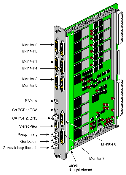
DG5-8 | VIO5H daughterboard | Eight high-resolution video outputs. |
DG5-2 | GVO daughterboard | Provides serial digital output from the GVO daughterboard. It adds two high-resolution video outputs with two CCIR601 outputs on two BNCs. |
DG5-2 | TVO (HD–GVO) daughterboard | Provides two high-resolution video outputs and two high-definition graphics TMDS video outputs (TVO). |
DG5-2 | DPLEX daughterboard | The Digital Video Multiplexer (DPLEX) option provides specialized, high-resolution, digital and analog imagery capabilities by cascading the video outputs of two or more graphics pipes and outputting them to a single monitor or other video input device. |
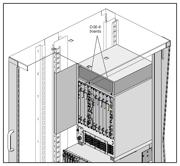
The DG5 board is always placed in the rightmost graphics board slot in each board set (pipe) in the G-brick. Figure 2-6 illustrates this placement with two DG5-8 boards installed in the G-brick.
The DG5 board requests and receives digital frame buffer pixel data from the RM board set. The DG5 board processes the pixel data and streams it onto the video packet bus. The DG5 board also handles all pixel clocking, genlocking, and cursor display functions.
From the packet bus, processed video can be sent to one of the video output channels, or to the NTSC or PAL encoder (VTR channel). The encoder does not provide broadcast quality signals. The video output controller supplies data to a 3-DAC array that feeds out the analog RGB signals. NTSC or PAL circuitry signals are sent from the VOC through encoder and field buffer RAMs.
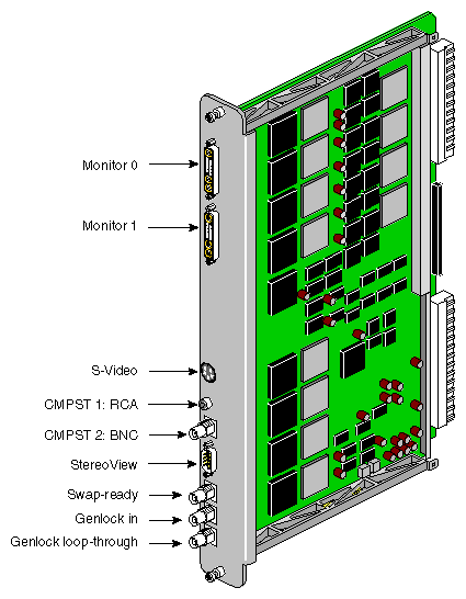
All the DG5 boards have standard connectors. Table 2-2 lists and describes these standard board connectors.
Table 2-2. DG5 Board Standard Connector Descriptions
Label | Type | Function |
|---|---|---|
Monitors 0 through X | 13W3 | Variable high-resolution monitor outputs |
S-Video | 4-pin mini-DIN | Interface to SVHS VCR or monitor |
CMPST 1 | RCA jack | Interface to composite monitor or VCR |
CMPST 2 | BNC | Interface to composite monitor or VCR |
StereoView | 9-pin sub-D | Interface to StereoView device |
Swap–ready | BNC | Interface to other graphics pipes |
Genlock in | BNC | Interface to house sync or other pipes |
Genlock loop–through | BNC | Loop-through connection |
Figure 2-7 shows the 13W3 pinouts for the monitor connectors on the I/O panel of the DG5 boards. The 13W3 connector on each DG5 board uses the same pinout pattern.
In the A1, A2, and A3 connectors, the center conductor carries the video signals. The outer conductors of the A1, A2, and A3 connectors are their video returns, which are tied to the monitor's grounded chassis.
Figure 2-8 shows the connectors for the basic DG5-2 board, which has no daughterboard. For functional descriptions of these connectors, see “DG5 Board Standard Connector Descriptions”.
Figure 2-9 shows connectors on the panel for the DG5-8 option board with the VIO5H daughterboard, which adds several monitor connectors to a basic DG5-2 board that has no daughterboard. For functional descriptions of the DG5-8 connectors, see “DG5 Board Standard Connector Descriptions”.
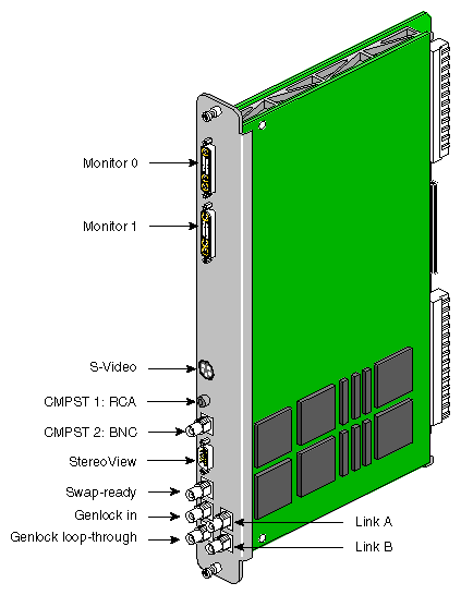
The graphics-to-video (GVO) option daughterboard comes assembled with the basic DG5-2 board and is designed to provide direct output from graphics to video in real–time through its two CCIR601 connectors implemented as BNCs (link A and link B connectors). For functional descriptions of the DG5-2 board connectors, see “DG5 Board Standard Connector Descriptions”.
Figure 2-10 shows connectors on the panel for the DG5-2 board with optional GVO daughterboard combination.
Figure 2-11 shows the connectors on the rear panel of the DG5–2 board with an optional TVO (HD–GVO) daughterboard.
The TVO daughterboard adds the Transition Minimized Differential Signaling (TMDS) video output connectors to the DG5-2 board, which are used to connect the graphics system to a High–Definition Graphics Video Output (HD–GVO) system.
For descriptions of the standard DG5-2 board connectors, see “DG5 Board Standard Connector Descriptions”.
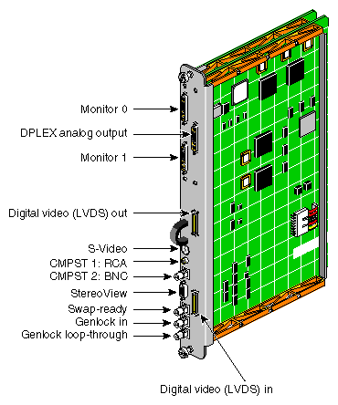
Each DPLEX option assembly, shown in Figure 2-12, is essentially composed of a DG5-2 board with an attached DPLEX daughterboard that adds a DPLEX analog output, a digital video low voltage differential signaling (LVDS) out and a digital video LVDS in connector. The DPLEX daughterboard and its connectors allow you to join or "cascade" the video outputs of two or more graphics pipes and output them to a single monitor or other video device (such as a video projector).
The pipes in the DPLEX cascade are always linked using LVDS, swap–ready, and genlocking (sync) cables. For a functional description of the DG5-2 board connectors, see “DG5 Board Standard Connector Descriptions”.
The V–brick has slots for either one or two InfinitePerformance pipes to provide advanced graphics capabilities for your SGI Onyx 3000 series graphics system.
The following are the V–brick's internal components and front panel items. Figure 2-13 shows the items located on the V–brick front panel.
Internal components:
Power board. This board provides power to the V–brick.
Midplane PCA. The V–brick midplane contains an Xbridge ASIC that is the interface between the V–brick's two ports and the V12 boards (see Figure 2-14). The midplane also has receptacles for the compression connectors of the V12 boards.
Front panel items:
L1 controller and display. The L1 controller generates V–brick status and error messages that appear on the liquid crystal display (LCD).
On/Off switch with LED. Press this button to power on the V–brick internal components. Alternatively, you can power on the V–brick internal components at a system console.
L1 controller switches and LEDs:
On/Off switch LED. This LED lights green when the V–brick internal components are powered on and turns off when they are powered off.
Service required LED. This LED lights orange to indicate that an item is broken or not operating properly (for example, a fan is off), but that the V–brick is still operating.
Failure LED. This LED lights red to indicate that a system failure has occurred and the V–brick system is down.
Fans.
The V–brick midplane contains an Xbridge ASIC that is the interface between the V–brick's two ports and the V12 boards in the board slots, as shown in Figure 2-14, a block diagram of the V–brick. The midplane also has receptacles for the compression connectors of the V12 boards.
The V–brick has four board slots to support either one or two V12 boards. Each V12 board requires two board slots.
Figure 2-15 shows the location of the power switch, two V12 boards, connectors, and LEDs on the V–brick rear panel.
The V–brick has the following rear-panel items:
Power switch. Move the power switch to the On (1) position to power on the V–brick's L1 controller, and move it to the Off (0) position to power off the V–brick's L1 controller. Powering on the L1 controller lights the 12 VDC LED green.
48 VDC and 12 VDC LEDs. When you move the power switch to the On (1) position, these LEDs light up. The 12 VDC lights green when the L1 controller is powered on and operating, and the 48 VDC lights green when the rest of the V–brick internal components are powered on and operating. Press the On/Off switch located on the L1 controller front panel to power on the internal components.
PWR (power) connector. This connects to the power bay to supply power to the V-brick.
Slot 1, slot 2, slot 3, and slot 4. These slots are used to install and replace V12 boards in your graphics system. Each V12 board requires two slots.

Warning: To avoid personal injury or damage to your system, only qualified SGI system support engineers (SSEs) can install and replace V12 boards. XIO 11 and XIO 10 connectors. These connectors connect the V–brick to a C–brick. Only one connector is required to connect to a single C–brick. As an option, in V–bricks that contain one InfinitePerformance pipe, the second connector can be connected to another C–brick to create a dual-ported V–brick, which would provide greater bandwidth. The connection to a another C–brick would occur only in situations where another C–brick was not already used to support a second V12 board.
XIO 11 and XIO 10 connector LEDs. These LEDs light yellow when the connector is cabled securely to the C–brick device. They light green when the connection is negotiated with the device with which the connector is cabled.
Figure 2-16 shows the connectors and LEDs on a InfinitePerformance graphics pipe (V12 graphics board). The following is a functional description of these connectors and LEDs:
Two Digital Video Interface–Integrated (DVI–I) analog or digital connectors to connect monitors to the SGI Onyx 3000 series graphics system.
13W3 analog connector that is not operable (this connector is blocked).
One genlock connector to synchronize multiple V12 boards with each other.
One swap–ready connector to synchronize the swap buffers in order to synchronize two or more V12 boards to as many as four V–bricks and four V12 boards.
Stereo connector to connect to an emitter to provide stereo effect for LCD shutter glasses.
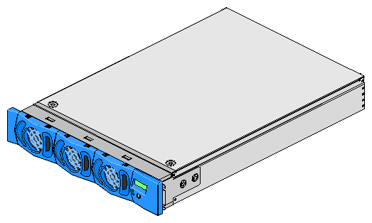
The N–brick, which has four pairs of connectors (800 MBytes in each direction), is used in the place of as many as four X–brick or I–bricks to connect up to four C–bricks to four InfiniteReality pipes (two in each of two G–bricks). This is a cost and space efficient solution when you do not require the additional I/O capability provided with an X–brick or extra I–brick and when you want to save rack space (the N–brick is a 2U-sized brick). For N–brick sample cabling configurations, see Chapter 3, “Configurations and Cabling”.
| Note: The N–brick is an option only for the InfiniteReality graphics system, which includes a G–brick. |
The following list describes the N–brick's internal components and front panel items. Figure 2-17 shows the N–brick's front panel items.
Internal components:
Printed circuit board (PCB) with port connectors.
Power board.
Front panel items:
L1 controller and display. The L1 controller generates N–brick status and error messages that appear on the liquid crystal display (LCD).
On/Off switch with LED. This LED powers on the N–brick internal components.
L1 controller LEDs and switches:
On/Off switch LED. This LED lights green when the N–brick internal components are powered on and turns off when they are powered off.
Service required LED. This LED lights orange to indicate that an item is broken or not operating properly (for example, a fan is off), but that the N–brick is still operating.
Failure LED. This LED lights red to indicate that a system failure has occurred and the N–brick system is down.
Fans. The N–brick has two hot-swappable fans.

Warning: To avoid personal injury and to avoid damage to your system, these N–brick fans, which are N+1 redundant, can be hot-swapped only by your SGI system support engineer (SSE).
Figure 2-18 shows the location of the power switch, connectors, and LEDs on the N–brick rear panel.
The N–brick has the following rear panel items.
PWR (power) connector. This connects to the power bay to provide power to the N-brick.
Power switch . Move the power switch to the On (1) position to powers on the N–brick, and move it to the Off (0) position to powers off the N–brick. Move the power switch to the On (1) position to power on the L1 controller. Press the On/Off switch (brick reset button) to power on the rest of the N–brick internal components.
48 VDC and 12 VDC LEDs. The power switch must be in the On (1) position for these LEDs to be on. The 12 VDC lights when the L1 controller is operating, and the 48 VDC lights when the rest of the N–brick internal components are powered on.
C–brick 0 through C–brick 3 connectors. Connectors C–brick 0, C–brick 1, C–brick 2, and C–brick 3 connect to the XIO (II) I/O interface connectors on the C–bricks.
Graphics pipe 0 through Graphics pipe 3 connectors. Connectors Graphics pipe 0, Graphics pipe 1, Graphics pipe 2, and Graphics pipe 3 connect to the connectors on the G–brick Ktown2 board. As you face the rear panel of the G–brick, the top Ktown2 connector is connected to the rightmost InfiniteReality pipe (set of graphics boards), and the bottom Ktown2 connector is connected to the leftmost InfiniteReality pipe.
Graphics pipe and C–brick connector LEDs. All of these connectors have two LEDs as follows:
The green LED (the hardware LED) lights to indicate that a cable is connected properly between the N–brick and another brick.
The yellow LED (the software LED) lights to indicate that packets are being transferred successfully across the link.
