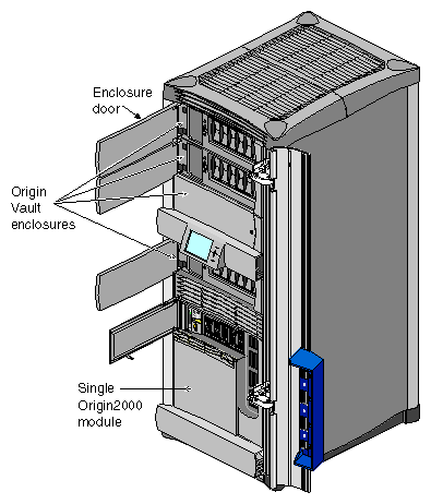
This chapter describes how to set up an Origin Vault standalone tower or rackmountable enclosure. Sections are
| Warning: Removing the Origin Vault tower from its package or lifting an Origin Vault rackmountable enclosure into a rack requires two people. |
When setting up an Origin Vault tower, keep in mind the following.
Removing the Origin Vault option from its package requires two people.
When opening the chassis to install or remove peripherals, always observe proper electrostatic discharge (ESD) procedures. Make sure you are properly grounded with a wrist or heel strap before handling drive assemblies.
For further considerations for the Origin Vault tower, see the next section, “Choosing a Location for the Origin Vault Tower.”
Follow these guidelines:
If the standalone tower is connected to an Origin200 system, both systems must be plugged into the same grounded power circuit; otherwise, loss of signal integrity or possible damage to components on the Origin200 main system board can result.
Any difference in ground potential greater than 500 millivolts (0.5 volts) between two chassis connected together with CrayLink™ or XTown cables can cause severe equipment damage, and can create hazardous conditions.
Be sure that there is a properly rated electrical outlet available near enough for the power cable to reach.
Use an uninterruptable power supply when possible.
Make sure that the surface on which you place the tower can support at least 60 lbs (27 kg) over an area of 9.25 inches (23.5 cm) by 26.5 inches (67.3 cm). These dimensions take into account the widest setting for the tower feet.
Select a site that is clean and dust-free and that does not produce excessive vibration or other extreme conditions.
Provide four inches (2.5 cm) clearance around all sides of a tower for proper air flow.
For more information, consult the latest version of the Site Preparation for Origin Family and Onyx2.
Move the box(es) to the site you have selected (Origin Vault tower) or to the Origin Rack location (Origin Vault rackmountable chassis).
Remove the Origin Vault option from its packing.
| Warning: Removing the Origin Vault option from its package requires two people. |
For the standalone tower:
If you are resetting the 3.5-inch drive device IDs from the default (1 through 6) to 9 through 14 (such as for installations in which one host accesses two Origin Vaults), proceed to the next section, “Jumpering SCSI Device IDs”.
If you are not resetting 3.5-inch drive device IDs, swivel the feet out to the position you want and proceed to the section “Installing 3.5-Inch Drives”.
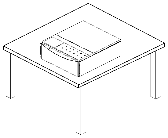
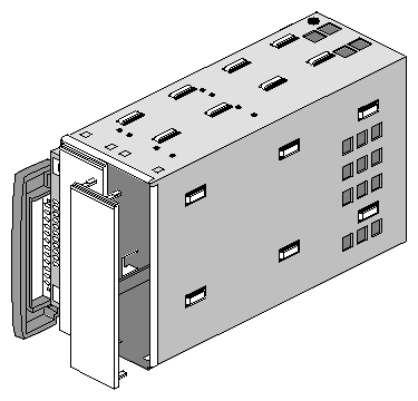
If you have a rackmountable chassis, set it flat on a work surface with the door facing out, as shown in Figure 2-1.
If you are resetting the 3.5-inch drive device IDs from the default (1 through 6) to 9 through 14, proceed to the section “Jumpering SCSI Device IDs”. Otherwise, proceed to the section “Installing the Origin Vault Enclosure in a Rack”.
The default SCSI device IDs for the drives are 1 through 6, starting at the drive farthest from the on/off button. For installations in which one host uses two Origin Vault options, you must reset the drives on one Origin Vault option to the higher number set, namely 9 through 14. Select the higher number set by placing a jumper (included inside the Origin Vault option) over certain pins. To do so, follow these steps:
Have ready a #2 Phillips screwdriver and a pair of needle-nosed pliers.
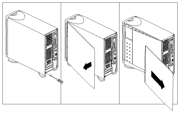
For an Origin Vault tower, remove the side panels, as shown in Figure 2-2.
Lay the tower or rackmountable enclosure on a work surface with the top cover facing up, as shown in Figure 2-1.
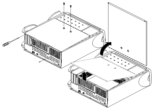
Remove the two screws at the rear of the chassis that secure the top cover and remove the top cover. See Figure 2-3.
Be careful not to touch components within the chassis.

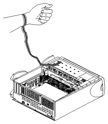
Warning: Do not attempt to open the power supply at any time. Ground yourself with a wrist strap, as shown in Figure 2-4. The grounding strap is included in the Origin Vault shipment.
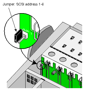
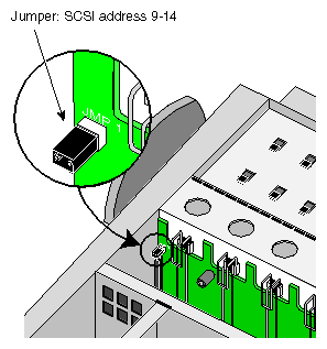
Locate the ID-setting pins near the outer edge of the 3.5-inch backplane; see Figure 2-5. Notice the jumper (shunt) that is inserted over one pin.
Using the needle-nosed pliers, lift the jumper off the pin and slide it over both pins. See Figure 2-6.
Remove the grounding strap and close the Origin Vault, reversing the procedures in step 4.
If you are setting up an Origin Vault tower, replace the side panels, set the tower upright, and, if desired, adjust the tower feet. Skip the next section and proceed to “Installing 3.5-Inch Drives”.
If you are setting up a rackmountable enclosure, proceed to “Installing the Origin Vault Enclosure in a Rack”.
| Warning: Lifting the Origin Vault rackmountable enclosure into a rack requires two people. |
You can install the Origin Vault enclosure in
Different marketing codes have appropriate hardware for the various racks, as summarized in Table 2-1.
Table 2-1. Rackmount Enclosure Hardware
Feature | For Origin2000 Rack or P-S-RACK | For Third-Party 19-Inch Rack or P-S-RACK |
|---|---|---|
Door design | Bottom hinge | |
One (used only if door is removed) | ||
Mounting hardware | ||
Not included | ||
Faceplate/door preinstalled | No | Yes |
Structured to | P-S-B6X4B-DF-R, P-S-B6X9B-DF-R, P-S-BOXB-DF-R | P-S-BOX2B-DF-R |
Installing the Origin Vault enclosure in a rack is described in these sections:
The last three sections pertain to all types of racks.
| Note: These procedures require a #2 Phillips screwdriver. |
In an Origin2000 Rack or the P-S-RACK, the enclosure rests on rails, which are supplied in the rack.
The Origin Vault enclosure for the Origin2000 Rack includes mounting ears, with screws. These mounting ears are not weight-bearing, but serve to secure the enclosure in the rack and prevent it from sliding out.
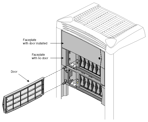
The Origin Vault enclosure shipment for the Origin2000 Rack includes a faceplate with a door that is hinged at the left. The faceplate snaps into the mounting ears after it is installed in the rack. You can remove the door; an end cap is included to cover the mounting flange that is exposed, as explained in “Removing the Enclosure Door (Optional)”.
Preparing the rack and the enclosure consists of
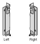
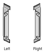
The U-shaped mounting ears are for the left (part number 040-1763-001) and right (part number 040-1764-001) sides of the Origin Vault enclosure; they are not interchangeable. See Figure 2-7.
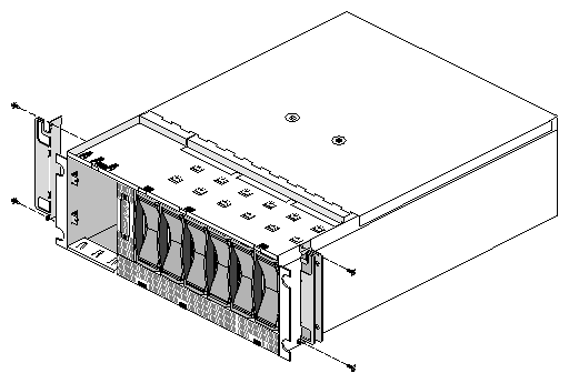
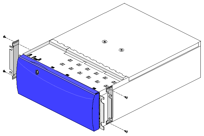
Using a #2 Phillips screwdriver and the screws provided with the Origin Vault enclosure, fasten the appropriate ear to each side of the enclosure behind the front flange, as shown in Figure 2-8. Use two screws for each mounting ear.
The Origin2000 Rack provides front and rear access. In the Origin2000 Rack, the rear is where the main power switch is located, as well as all of the connectors.
To prepare the Origin2000 Rack, follow these steps:
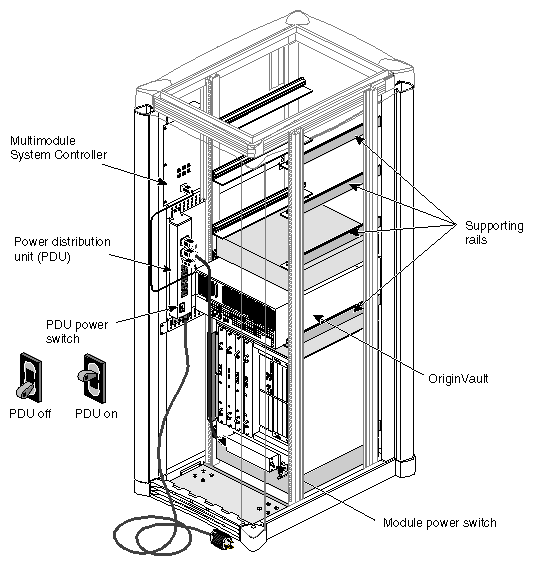
Open the front and rear of the rack. Plan where in the rack to install the enclosure. Figure 2-9 shows locations; an Origin2000 Rack containing one module can accommodate as many as four Origin Vault enclosures.
Figure 2-10 shows rail placement in an Origin2000 Rack, with other features.
Power off the Origin2000 Rack, following procedures outlined in its manual.
If necessary, remove the filler panel for the bay you have selected for the Origin Vault enclosure.
Proceed to “Securing the Enclosure in the Rack”.
In an industry-standard third-party 19-inch rack, the Origin Vault enclosure rests on a shelf included with the Origin Vault enclosure. This mounting shelf takes up 4 U (7 inches, or 17.8 cm) of space and works in most 19-inch racks.
This Origin Vault enclosure shipment includes brackets (with screws) for securing the enclosure to the shelf.
The Origin Vault enclosure shipment for the third-party 19-inch rack also includes end caps for covering the ends of the front bezel if you want the enclosure door removed. Two pairs are included to accommodate the different widths of racks. Placing these end caps is explained in “Securing the Enclosure in the Rack”.
Preparing the rack and the enclosure consists of
The L-shaped mounting ears) are stamped “L” (part number 040-2007-001) and “R” (part number 040-2006-001) for left and right; they are not interchangeable. See Figure 2-11.
Using a #2 Phillips screwdriver and the screws provided with the Origin Vault enclosure, fasten the appropriate bracket to each side of the enclosure behind the front flange, as shown in Figure 2-12. Use two screws for each bracket.
Follow these steps to install the mounting shelf in the 19-inch rack:
Determine where in the rack you want to install the Origin Vault enclosure.

Note: The Origin Vault enclosure shipped for the 19-inch rack has a door that is hinged at the bottom. You can remove this door if desired. Locate four 10-32 x 1/2-inch screws and the four #10 washers included with the mounting shelf.
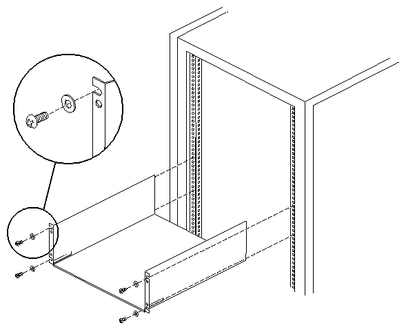
Place a washer between each screw head and the mounting shelf, as shown in Figure 2-13. Screw in the screws to install the mounting shelf.
For any type of rack, follow these steps to install and secure the Origin Vault enclosure:
If the front door of the Origin Vault rackmountable enclosure is not locked, use the key to lock it so that the door cannot be pulled open accidentally when the enclosure is being installed.

Warning: Lifting the Origin Vault rackmountable enclosure into a rack requires two people. If the enclosure contains peripherals, you can remove them to lighten the enclosure before you install it. Follow procedures in “Removing and Adding a 5.25-Inch Drive Option” and “Replacing and Adding a Disk Drive Module” in Chapter 3.
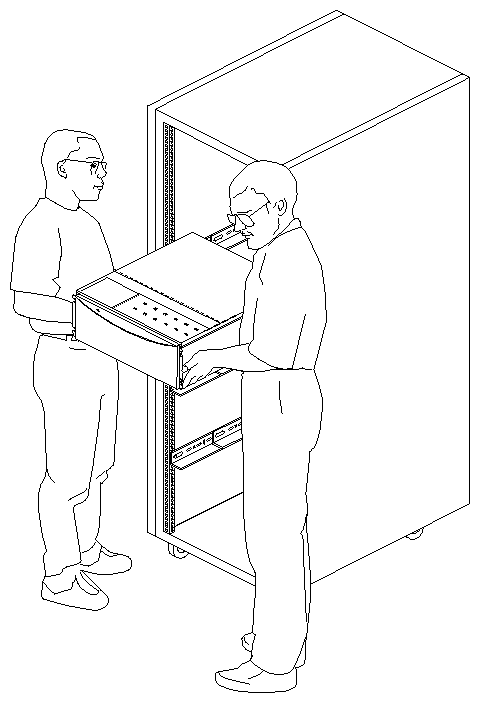
With a person on each side of the enclosure, lift it into the front of the rack, as shown in Figure 2-14. Place it on top of the side rails or shelf and slide it back into the rack.
Attach the enclosure to the rack, using the screw and fastener combination appropriate for the rack.
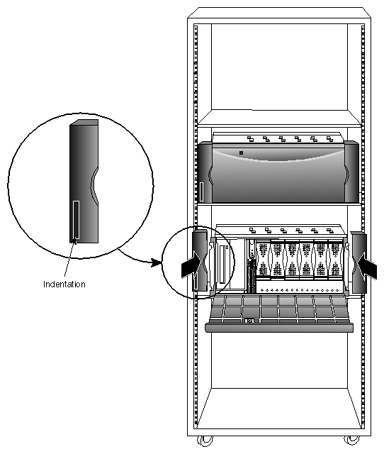
If the Origin Vault option has a bottom-hinged door, attach plastic end caps to conceal the mounting flanges, as shown in Figure 2-15. For the Origin SCSI expansion rack (P-S-RACK), use the larger pair of end caps; for a 19-inch third-party rack, use the smaller pair.
Attach the label to the indentation in the left end cap shown in Figure 2-15.
If the Origin Vault option has a side-hinged door, attach it by plugging it into the holes in the U-shaped mounting ears, as shown in Figure 2-16.
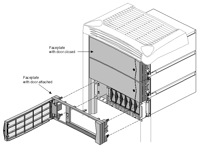
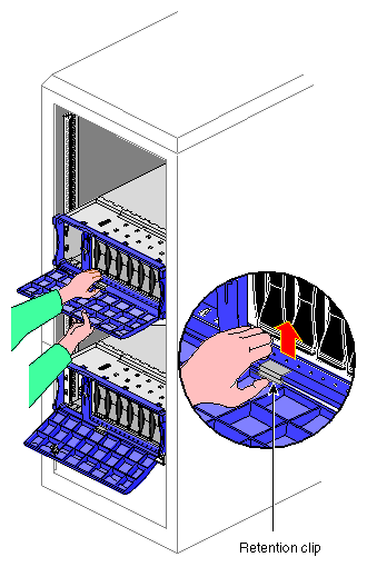
You may wish the enclosure door removed for easier access to the media. You can pull either type of door off its faceplate.
Figure 2-17 shows this operation in an Origin2000 Rack.
Use the single end cap provided to cover the end of the faceplate that is exposed when the door is removed.
Figure 2-18 shows this operation in a third-party rack. Move the retention clip out of the way, continue pulling the door down, and it comes off.
Before you cable the Origin Vault enclosure, note the following:
The Origin Vault enclosure package includes two SCSI cables: two 1-meter cables for the single-ended version, a 1-meter and a 10-meter cable for the differential version. Use only these cables.
Make sure the SCSI channel you are using on the host system matches the type of expansion option you ordered.
By default, the Origin2000 host system SCSI connector on the BaseIO panel is single-ended. Ultra SCSI XIO board output channels 0, 1, 2, and 3 are differential; channel 0 is autosensing to work with either differential or single-ended SCSI devices. However, channel 0 is not suitable for use with the Origin Vault's single-ended or differential 3.5-inch drives.
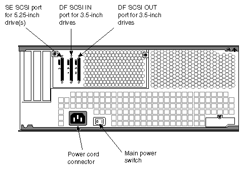
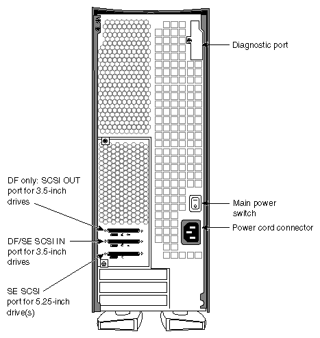
Figure 2-19 shows the SCSI connectors on the back of the enclosure.
This section explains
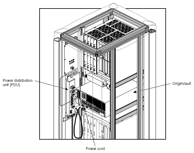
Connect the Origin Vault power cord to the Origin Rack power distribution unit, as shown in Figure 2-20.
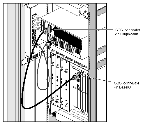
If the host is in the same rack, use the 1-meter SCSI cable to connect the single-ended 3.5-inch drives to these ports:
the SCSI port on an Origin2000 IO6 board
the port on the single-ended version of the PCI SCSI board; see Figure 2-21
| Note: Do not use channel 0 on the optional Ultra SCSI XIO board for the 3.5-inch drives. |
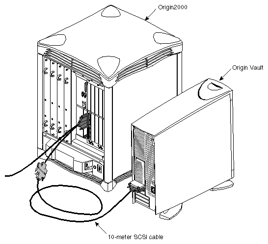
Figure 2-22 shows cabling to the IO6 board in an Origin2000 server.
To cable the differential 3.5-inch drive controller, plug the 10-meter SCSI cable into the IN SCSI connector (the middle port) on the Origin Vault option. Connect the other end to
Ultra SCSI XIO board channel 1, 2, or 3 (not 0)
the port on the differential version of the PCI board; see Figure 2-21

Note: Do not use channel 0 on the optional Ultra SCSI XIO board for the 3.5-inch drives. Also, do not use the SCSI connector on the host BaseIO panel, which is single-ended.
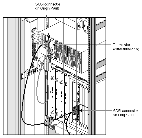
If the Origin Vault enclosure is interfacing with the Ultra SCSI option board, cable the Origin Vault SCSI to a SCSI connector of one of the Y cables supplied with the Ultra SCSI board option, not directly to the board, as shown in Figure 2-23.
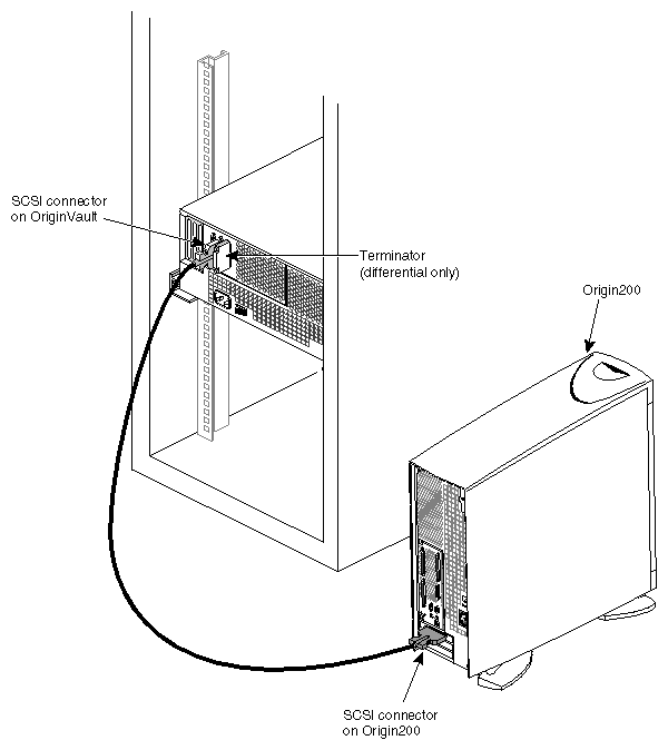
For a differential Origin Vault, if the host is not in the same rack, use the 10-meter SCSI cable supplied with the enclosure to connect the 3.5-inch drive controller's IN SCSI connector (the middle port) to a differential SCSI connector in the host. Figure 2-24 shows cabling to a differential PCI option board in an Origin200 tower.
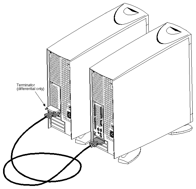
Attach a terminator (part number 9660006; included in the differential Origin Vault shipment) to the OUT SCSI connector if it does not already have one, unless you are adding a second host or Origin Vault option, as explained in “Adding a Second Origin Vault Expansion Option (One Host)”, “Adding a Second Host to One Origin Vault Expansion Option”, or “Adding a Second Host and Second Origin Vault Expansion Option”.
If peripherals are present in the 5.25-inch drive bay, connect this controller port to a single-ended SCSI port in the host with the second 1-meter cable included with the option. For the 5.25-inch drives, you can use either
channel 0 on the optional Ultra SCSI XIO board
the port on the single-ended version of the PCI SCSI board; see Figure 2-21
If the Origin Vault enclosure is interfacing with the Ultra SCSI option board, you cable the Origin Vault SCSI to a SCSI connector of one of the Y cables supplied with the Ultra SCSI board option, not directly to the board.
The SCSI device IDs of the 3.5-inch bays in the Origin Vault are numbered 1 through 6 (or 9 through 14), starting farthest from the power button. The SCSI backplane automatically sets the SCSI ID of the disk drive in each bay.
Disk drives ordered from Silicon Graphics are preconfigured; you can install them in the bays with no additional configuration. If you are installing third-party peripherals, or wish to change the configuration of a Silicon Graphics supplied drive, follow these guidelines:
Set the SCSI device numbers from 1 to 6 or from 9 to 14.
Setting the drives to device numbers 9 through 14 is explained in “Jumpering SCSI Device IDs”.
Do not use
SCSI ID 0, which is reserved for the controller
SCSI ID 7, which is reserved for the second host adapter in dual-host configurations
Note that the 5.25-inch drive bay and the 3.5-inch drives are on separate SCSI buses in the Origin Vault.
Set the drive (motor) start jumper to start on command from the host. Do not configure the drive to start as soon as power is applied, because this setting might draw too much current when the system is first turned on. Options from Silicon Graphics have this jumper set correctly.
| Note: If you are replacing a 3.5-inch drive, see “Replacing and Adding a Disk Drive Module” or “Warm Swapping Drives (Administrative Warm Swap)” in Chapter 3, “Operating the Origin Vault Expansion Option.” |
To install a 3.5-inch drive, follow these steps:
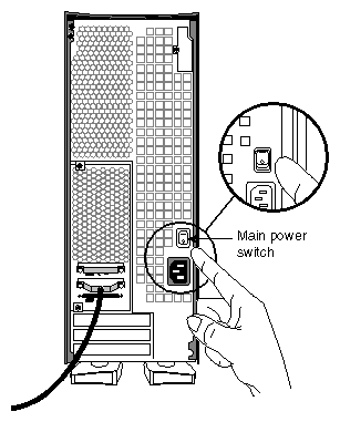
At the back of the tower or chassis, make sure that the main power switch is turned off, as shown in Figure 2-25.
Unlock and open the Origin Vault front door using the key included with the option.
Attach the grounding strap to ground yourself to a metal part of the Origin Vault.
For each drive you are installing, remove a blanking panel from a drive bay, starting with the bay farthest from the on/off button. See Figure 2-26.

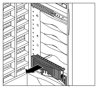
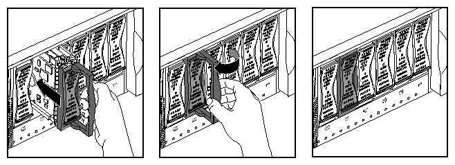
Note: Save the blanking panel(s) you remove. If you need to remove a drive and do not replace it with another one, you must reinstall the blanking panel to ensure proper cooling and electromagnetic interference (EMI) shielding in the Origin Vault chassis. Insert each drive sled into a bay until it is almost flush with the edge of the drive bay, as shown in Figure 2-27 and Figure 2-28.
Latch the drive: For a tower, pull the handle up to latch the drive; for an enclosure in a rack, pull the handle to the left.
To avoid drives becoming mixed up if they are removed later from their bays, label each drive SCSI 1, SCSI 2, and so on through SCSI 6 (or 9 through 14, if you have jumpered the pins on the 3.5-inch drive backplane to give the drives the higher number set, as explained in “Jumpering SCSI Device IDs”).
Remove the grounding strap.
Optional 5.25-inch drives are housed in a peripheral carrier, which accommodates one full-height drive (such as a DLT tape drive) or two half-height drives (such as a CD-ROM drive and a DAT tape drive).
Peripherals ordered from Silicon Graphics are preconfigured; you can install them in the 5.25-inch peripheral carrier with no additional configuration. If you are installing third-party peripherals, or wish to change the configuration of a Silicon Graphics supplied drive, follow these guidelines:
Set the SCSI device ID between 1 and 15. Do not use SCSI ID 0, which is reserved for the controller. Note that the 5.25-inch drive bay and the 3.5-inch drives are on separate SCSI buses in the Origin Vault.
Set the drive (motor) start jumper to start on command from the host. Do not configure the drive to start as soon as power is applied, because this setting may draw too much current when the system is first turned on. Options from Silicon Graphics have this jumper set correctly.
The installation process consists of these steps:
These procedures require a #2 Phillips screwdriver.
To prepare the peripheral carrier for the peripheral(s), follow these steps:
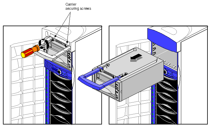
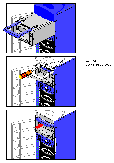
To remove the peripheral carrier, use a #2 Phillips screwdriver to unscrew the two screws that secure the peripheral carrier to the Origin Vault chassis, as shown in Figure 2-29. Reserve the screws.
Grasp the handle of the peripheral carrier; the handle slides out about an inch. Pull the carrier out of the bay, supporting it with your other hand. See Figure 2-29.
Place the peripheral carrier on a work surface. Remove the EMI shielding plate from the rear of the peripheral carrier:
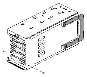
Unscrew the screw at the bottom of the EMI shielding plate on either side of the carrier, as shown in Figure 2-30.
Pull the shielding plate out from the bottom and then down. This plate has tabs that hook into slots at the top of the carrier.
At the front of the peripheral carrier, use a fingernail to pull out one or both blanking plates:
For a full-height drive or two half-height drives, remove both.
For one half-height drive, remove either the upper or lower blanking plate.
For ease of access during this installation process, you may wish to remove both plates, even if you are installing only one drive; you can reinstall the blanking plate for the empty side at the end of the process.
The blanking plates snap into and out of place with tabs at the top and bottom. See Figure 2-31.

Note: Save the blanking plate(s) you remove. If you remove a peripheral and do not replace it with another one, you should reinstall the blanking plate(s) to ensure proper cooling in the Origin Vault chassis.
To install drives in the peripheral carrier and insert the carrier into the Origin Vault, follow these steps:
If you are installing two half-height peripherals, check the orientation of their SCSI connectors. Note the configuration of the SCSI cable in the peripheral carrier.
Slide the peripheral(s) into the carrier from the front.
If you are installing one half-height peripheral only, align it flush with one side or the other of the carrier. At least two screw holes on the top of the carrier and two on the bottom must align with screw holes on the peripheral so that it can be secured in the carrier.
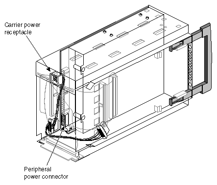
Attach a connector of the power cable to each peripheral; Figure 2-32 shows an example.
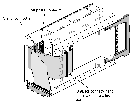
Attach one of the SCSI connectors on the carrier's internal SCSI cable to each peripheral; Figure 2-33 shows an example. If you are inserting only one peripheral, use either connector. Fold the excess cable lengths as appropriate.
If you are installing a DLT tape drive, use the SCSI connector in the middle of the cable, rather than the one near the end.
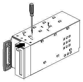
Push the peripheral all the way into the carrier so that the front is flush with the front of the carrier. Secure the peripheral(s) in the carrier with two screws on the top and two screws on the bottom of the carrier, as shown in Figure 2-34.
If all four screw holes align with holes in the peripheral, insert screws in the holes closest to the edge of the carrier.
Reattach the EMI shielding plate. If you have removed both blanking plates but installed only one half-height peripheral, reinstall the extra blanking plate.
Slide the carrier into the bay; note the orientation shown in Figure 2-35.
Make sure the peripheral carrier is flush with the front of the Origin Vault. The connectors on the rear of the peripheral carrier mate with connectors on the 5.25-inch backplane.
Screw the peripheral carrier in using the screws you reserved when you removed the carrier (see step 1 in “Preparing the Peripheral Carrier”).
To cable the standalone tower, follow these steps:
Locate the power cable and SCSI cable(s) included with your Origin Vault tower.
Locate the SCSI connectors on the tower; see Figure 2-36.

Caution: Make sure the SCSI driver on the host system matches the type (single-ended or differential) of expansion option that was ordered. If you connect a differential SCSI cable to a single-ended expansion option, the entire differential bus will shut down.
If you connect a single-ended SCSI cable to a differential expansion option, none of the drives in the Origin Vault will work.
By default, the SCSI connector on the BaseIO panel of the Origin2000 host system is single-ended. All Ultra SCSI XIO board channels are differential; channel 0 can be differential or single-ended. The PCI SCSI board option is available in single-ended or differential versions, as indicated by the icon near the board connector (see Figure 2-37).
Cable the SCSI connection(s):
Single-ended tower: Plug one of the 1-meter SCSI cables into the Origin Vault 3.5-inch controller port. Attach the other end of this cable to a single-ended SCSI connector in the host, such as the SCSI port on an Origin2000 IO6 board or the connector on the single-ended PCI option.
Differential tower: Use the Origin Vault 10-meter SCSI cable to connect the 3.5-inch drive controller's IN SCSI port (middle port) to a differential SCSI port on the host.

Note: Do not use channel 0 on the optional Ultra SCSI XIO board for single-ended or for differential 3.5-inch drives.
If peripherals are present in the 5.25-inch drive bay, use a 1-meter cable to connect this controller port to a single-ended SCSI port in the host, such as the SCSI port on an Origin2000 IO6 board or the connector on the single-ended PCI option.
For a differential Origin Vault tower, attach a terminator (part number 9660006; included in the differential Origin Vault shipment) to the OUT SCSI connector if it does not already have one, unless you are adding a second host or Origin Vault tower, as explained in “Adding a Second Origin Vault Expansion Option (One Host)”, “Adding a Second Host to One Origin Vault Expansion Option”, or “Adding a Second Host and Second Origin Vault Expansion Option”.
Figure 2-38 shows a differential Origin Vault tower cabled to an Origin2000 host system.
Figure 2-39 shows the SCSI cabling between a differential Origin Vault tower and an Origin200 host system.
Connect the power cable to the tower's power connector (see Figure 2-36) and plug the other end into a properly rated and grounded outlet. Do not turn on the Origin Vault system power at this time.
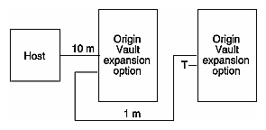
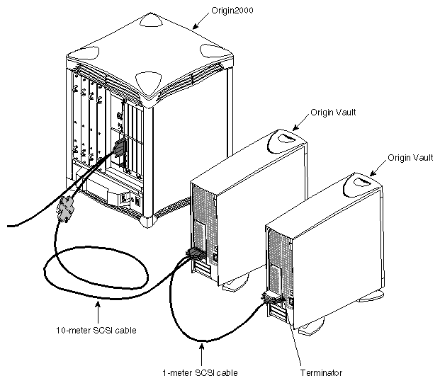
Figure 2-40 diagrams daisy chaining two Origin Vault expansion options.
Daisy chaining a second Origin Vault option requires
differential Origin Vault options only
different SCSI device IDs for the two Origin Vault options
a 1-meter cable between the options (one is supplied with each option)
a terminator on the unused SCSI connector of the second Origin Vault option
Follow these steps:
In the second Origin Vault option, select the alternate SCSI device ID (9-14), as explained in “Jumpering SCSI Device IDs”. The two Origin Vault options must have different SCSI device IDs.
If necessary, remove the terminator from the OUT SCSI port of the first Origin Vault option.
Plug one end of a 1-meter SCSI cable (such as that supplied with the second Origin Vault option) into the 3.5-inch OUT controller port of the first Origin Vault.
Plug the other end of this cable into the 3.5-inch drive's IN SCSI connector on the second Origin Vault.
If there is no terminator on the OUT SCSI connector on the second Origin Vault, attach one.
Figure 2-41 shows an example.
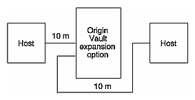
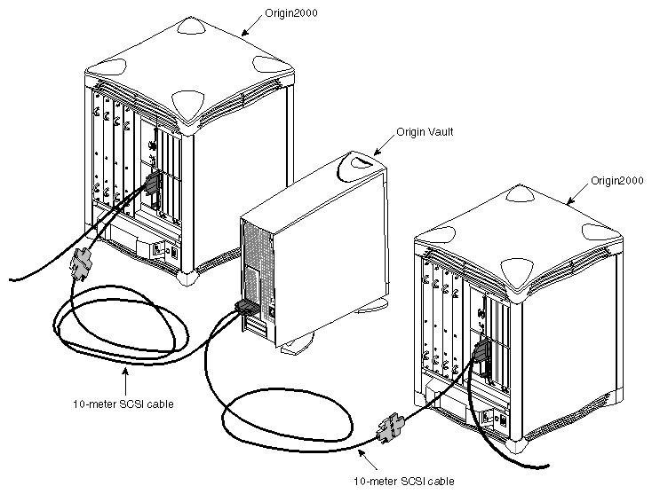
Figure 2-42 diagrams cabling two hosts to one Origin Vault expansion option.
A configuration in which two hosts share one Origin Vault option (dual-host, single-option) requires
a differential Origin Vault option only
different SCSI device IDs for the two hosts
a 10-meter cable between the second host and the Origin Vault (ordered separately; marketing code X-S-10M)
| Note: For dual-hosting, such as for an OPS or IRIS FailSafe configuration, qualified Silicon Graphics support personnel should follow configuration instructions in the appropriate manual. |
Follow these steps:
Make sure the second host has a different SCSI ID from the first: run printenv on each system. For example, the output for the first host might include the line
scsihostid=
which indicates a SCSI ID of 0, and the output for the second host might include
sscsihostid=7
The Origin Vault SCSI backplane automatically sets the 3.5-inch SCSI drive IDs to 1 through 6 or 9 through 14.
If necessary, remove the terminator from the OUT SCSI port of the Origin Vault option.
Plug one end of a 10-meter SCSI cable into the Origin Vault option's 3.5-inch OUT controller port.
Attach the other end of this cable to a differential SCSI connector in the second host, such as the Y cable to channel 1, 2, or 3 on the Ultra SCSI XIO board.
Figure 2-43 shows an example.
| Note: For dual-hosting, such as for an OPS or IRIS FailSafe configuration, qualified Silicon Graphics support personnel should follow configuration instructions in the appropriate manual. |
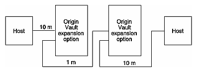
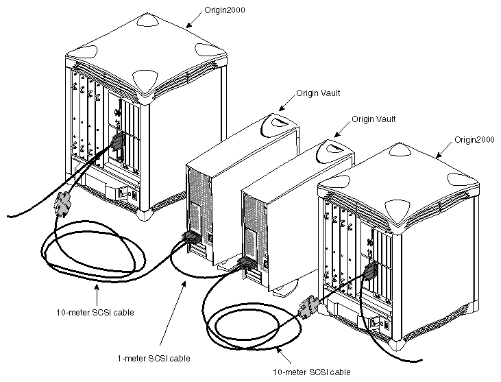
Figure 2-44 diagrams cabling two hosts to two daisy-chained Origin Vault expansion options.
A configuration in which two hosts share two Origin Vault options (dual-host, dual-option) requires
differential Origin Vault options only
different SCSI device IDs for the two hosts
different SCSI device IDs for the two Origin Vault options
a 1-meter cable between the two Origin Vault options
| Note: For dual-hosting, such as for an OPS or IRIS FailSafe configuration, qualified Silicon Graphics support personnel should follow configuration instructions in the appropriate manual. |
To add a second host and second Origin Vault option to the host and Origin Vault option you have just set up, follow these steps:
In the second Origin Vault option, select the alternate SCSI device ID (9-14), as explained in “Jumpering SCSI Device IDs”. The two Origin Vault options must have different SCSI device IDs.
Make sure the second host has a different SCSI ID from the first: run printenv on each system. For example, the output for the first host might include the line
scsihostid=
which indicates a SCSI ID of 0, and the output for the second host might include
sscsihostid=7
The Origin Vault SCSI backplane automatically sets the 3.5-inch SCSI drive IDs to 1 through 6 or 9 through 14.
Set up and cable the first host-option pair, attaching the 10-meter cable to the Origin Vault option's 3.5-inch IN controller port. Remove the terminator from the first option's OUT port.
Set up and cable the second host-option pair, attaching the 10-meter cable to the Origin Vault option's 3.5-inch IN controller port. Remove the terminator from the second option's OUT port.
Connect the two Origin Vault options with the 1-meter cable, cabling the two OUT ports.
Figure 2-45 shows an example.
| Note: For dual-hosting, such as for an OPS or IRIS FailSafe configuration, qualified Silicon Graphics support personnel should follow configuration instructions in the appropriate manual. |
Follow these steps to turn on the Origin Vault expansion option:
| Caution: For Origin Vault options that are part of a failover system, follow the startup instructions for that system. |
Make sure that the host system to which the Origin Vault is connected is powered off.
For an Origin Vault mounted in an Origin Rack, turn on the breaker for the rack if necessary.
At the rear of the tower or chassis, turn on the Origin Vault main power switch, as shown in Figure 2-46.
At the front of the tower or chassis, press the power button next to the 5.25-inch drive bay. The LED next to the button lights.
| Note: When the main power switch is on, a small amount of power flows to the expansion option even if the power button has not been pressed on (its LED is dark). |
Use the following checklist to determine if a drive is installed correctly in the Origin Vault tower or rackmounted enclosure:
When you power on the system, watch the drive LEDs. The LEDs should blink one after the other as they are accessed: first the 3.5-inch drives (sequentially), and then the 5.25-inch drives.
Check the system console; drives that are malfunctioning generate an error message on the system console as the system boots.
When the system boots in either single-user mode or multiuser mode, use hinv to see what is available. The drives should be listed; for example:
FPU: MIPS R10010 Floating Point Chip Revision: 0.0
CPU: MIPS R10000 Processor Chip Revision: 2.6
2 190 MHZ IP27 Processors
Main memory size: 64 Mbytes
Instruction cache size: 32 Kbytes
Data cache size: 32 Kbytes
Secondary unified instruction/data cache size: 1 Mbyte
Integral SCSI controller 0: Version QL1040B
  Disk drive: unit 1 on SCSI controller 0
  Disk drive: unit 2 on SCSI controller 0
  Disk drive: unit 3 on SCSI controller 0
  Disk drive: unit 4 on SCSI controller 0
  Disk drive: unit 5 on SCSI controller 0
Integral SCSI controller 1: Version QL1040B
Integral SCSI controller 7: Version QL1040B
  Disk drive: unit 1 on SCSI controller 7
  Disk drive: unit 2 on SCSI controller 7
  Disk drive: unit 3 on SCSI controller 7
  Disk drive: unit 4 on SCSI controller 7
  Disk drive: unit 5 on SCSI controller 7
  Disk drive: unit 6 on SCSI controller 7
  Disk drive: unit 9 on SCSI controller 7
  Disk drive: unit 10 on SCSI controller 7
  Disk drive: unit 11 on SCSI controller 7
  Disk drive: unit 12 on SCSI controller 7
  Disk drive: unit 13 on SCSI controller 7
  Disk drive: unit 14 on SCSI controller 7
Integral SCSI controller 8: Version QL1040B
Integral SCSI controller 9: Version QL1040B
Integral SCSI controller 10: Version QL1040B
IOC3 serial port: tty1
IOC3 serial port: tty2
Integral Fast Ethernet: ef0, version 1
IOC3 external interrupts: 1
Peripherals provided by Silicon Graphics are all recognized by the IRIX operating system and are ready to be configured for use with the system. For general reference on disks and filesystems, consult the latest edition of IRIX Admin: Disks and Filesystems.
Table 2-2 indicates where to get more information about configuring drives, depending upon how you want to use the drives in your system.
Table 2-2. Information for Drive Configuration
Operation | Reference (Man) Pages or Commands |
|---|---|
Creating device files | MAKEDEV(1M) (IRIX 6.2 and earlier only) mknod(1M) |
Disks |
|
Formatting and initializing | fx(1M) |
Volume header files, adding and removing | dvhtool(1M) |
Displaying partitions | prtvtoc(1M) fx(1M) |
Repartitioning | fx(1M) xdkm graphical tool |
System (boot) disk creation | PROM monitor (from the System Maintenance Menu) fx(1M), mkfs(1M), MAKEDEV(1M) dump(1M), xfsdump(1M) |
Mounted filesystem, adding | Add_disk(1) |
Use quotas | quota(1) |
Filesystems |
|
Creating an EFS or XFS | mkfs(1M) |
Spanning across multiple disks | xlv(7M) |
Mounting and unmounting | mount(1M), umount(1M) fstab(4) |
Automatically mounting (automount) | automount(1M) exportfs(4)
chkconfig(1M) |
