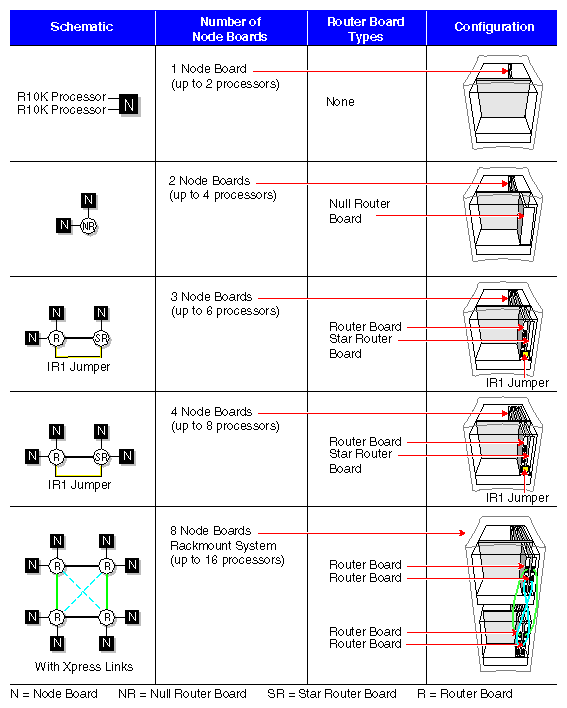
This chapter briefly describes some of the many configurations that are possible with the highly modular and scalable Origin2000 single-rack and multirack systems.
No matter which Origin2000 system you have, each configuration contains the following major hardware:
IP27 Node boards with one or two R10000 processors
main memory (which is located on the Node board)
a Router board(s)
a BaseIO board (which provides the system I/O ports such as serial, Ethernet, and SCSI interfaces)
single-connector assembly (SCA) drive bay(s) for single-ended, ultra SCSI drive installation
an Origin Vault™ drive box
The Origin2000 chassis is a standard 19-inch rack system that comes with a multimodule System Controller (MMSC) and display and also provides cable management hardware for CrayLink Interconnect and XIO cables.
| Note: Additional system modules or individual hardware components can be added to suit growing computational and I/O requirements. |
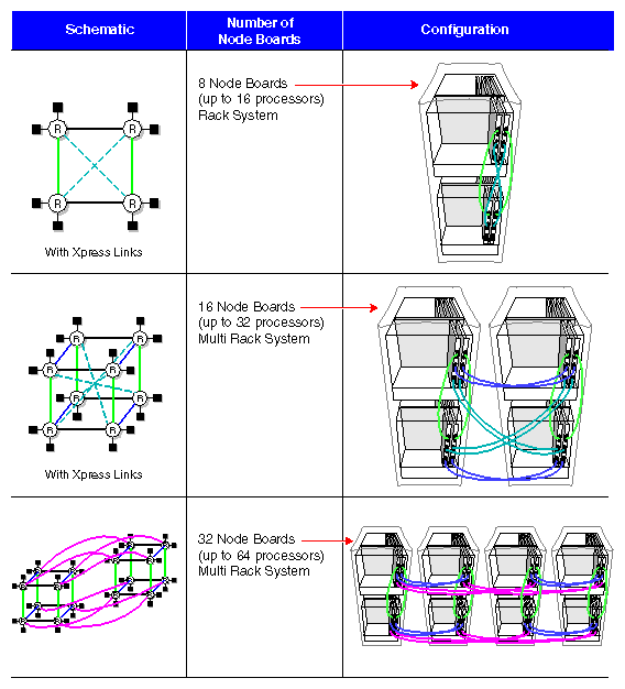
Figure 4-1 and Figure 4-2 shows various system configurations based on the number of processors in the system. These figures provide information on the type of Router board(s) that are required to support that configuration. The diagrams also show how the Origin2000 system expands from a basic building block module to a multimodule, multirack configuration.
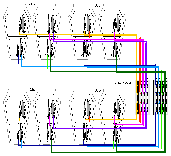
As Figure 4-1 shows, a base module also known as the Origin2000 deskside chassis supports 1 to 8 processors. To go beyond eight processors, a rackmount system is needed. Figure 4-2 shows a configurations with more than 16 processors or 8 Node boards requiring at least two rack systems. Larger configurations with 32 processors or 16 Node boards require four racks. The largest configurations with greater than 64 processors (up to 128) not only require even more racks, but also a different type of Router hardware called a Cray Router (see Figure 4-2). For additional information on routers, see Chapter 2, “Chassis Tour.”
Figure 4-3 through Figure 4-5 show different single rackmount Origin2000 configurations. The single rackmount systems have either one or two modules. Table 4-1 and Table 4-2 summarize the range of hardware components that can be supported by either a one or two-module configuration.
Table 4-1. Single Module Chassis Configurations
Hardware Component | Number Range |
|---|---|
IP27 Node boards | 1 to 4 |
R10000 CPUs | 2 to 8 |
Main memory per Node board | 64 MB to 4 GB (using 256 MB memory DIMMs) |
Main memory per chassis | 64 MB to 16 GB (using four Node boards) |
Number of internal SCA drives | 1 to 5 |
Number of usable XIO slots | 6 or 12 for a single-module chassis; |
Number of Origin Vaults | 1 to 4 (one Vault comes standard with the rack). |
I/O interfaces | - One (single-ended) SCSI connector |
Table 4-2. Dual Module Chassis Configuration
Hardware Component | Number Range |
|---|---|
IP27 Node boards | 2 to 8 |
R10000 CPUs | 2 to 16 |
Main memory per Node board | 64 MB to 4 GB (using 256 MB memory DIMMs) |
Main memory per chassis | 128 MB to 32 GB (using eight Node boards) |
Number of internal SCA drives | 2 to 10 |
Number of usable XIO slots | Up to 24 for a dual-module chassis |
Number of Origin Vaults | 1 only |
I/O interfaces | - One to two (single-ended) SCSI connector
|
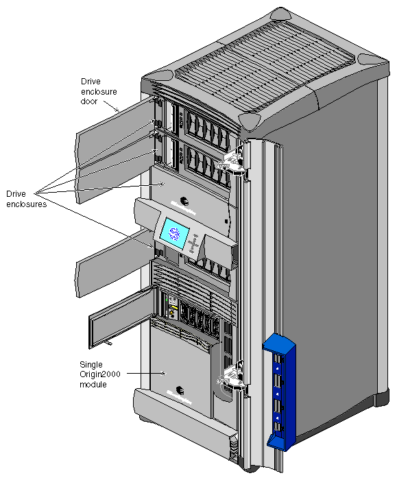
Figure 4-3 shows a single-module Origin2000 rackmount system. This configuration can house up to four Origin Vault drive boxes and two to eight CPUs. If desired, this rack can be cabled to other racks using the CrayLink Interconnect. This allows the other Origin2000 systems in the configuration to have high-speed access to those drives.
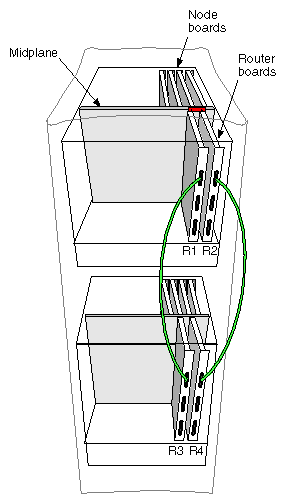
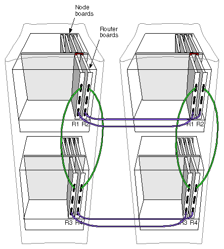
Figure 4-4 shows a 16”P” (or 16 CPU) rackmount system attached with CrayLink Interconnect cabling. This configuration requires two Rack Router boards in each module and supports a maximum of sixteen CPUs. In this system setup, the hardware resources (such as main memory and disk storage capacity) from one module can be quickly and efficiently accessed by the other system module.
| Note: It is possible to have a 16P configuration without CrayLink Interconnect cabling; however, the modules cannot share resources or communicate using the fast 1600-MB/sec transmission link. This type of configuration normally uses a different router board, either a Null Router or Star Router. For more information on the different types of router boards, see Chapter 2, “Chassis Tour.” |
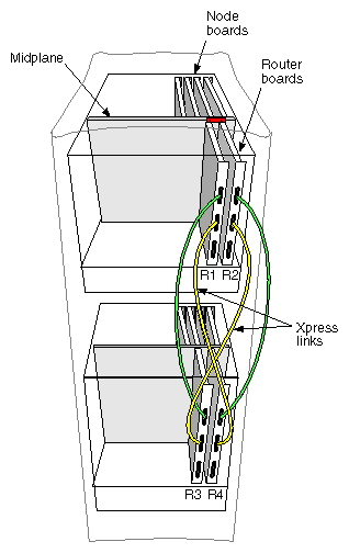
Figure 4-5 shows a 16P configuration using a combination of CrayLink Interconnect cabling and Xpress links. The Xpress links can effectively double the interconnect bandwidth within a rack by providing additional 1600-MB/sec routing paths.
| Note: Xpress links can double interconnect bandwidth in single rack systems. |
Sample Origin2000 multirack configurations are shown in Figure 4-6 through Figure 4-9. These can be large system configurations requiring a significant amount of floor space, along with special power and cooling considerations. The multirack configuration can have between 4 and 128 processors, up to 256 GB of main memory, and up to 192 XIO slots through 16 separate system modules. If you are considering expanding your current configuration, be sure to consult the Origin2000 Site Preparation Guide (p/n 007-3452-nnn), along with your facilities engineer, a reputable electrician, and your Silicon Graphics system support engineer (SSE).
Table 4-3 lists the number of various hardware components that can be supported through a multirack configuration.
Table 4-3. Multiple-Rack Configurations
Hardware Component | Number Range |
|---|---|
Number of racks | 2 to 8 |
IP27 Node boards | 2 to 64 |
R10000 CPUs | 2 to 128 |
Main memory per Node board | 64 MB to 4 GB (using 256-MB memory DIMMs) |
Main memory per chassis | 128 MB to 32 GB (using eight Node boards) |
Main memory (entire configuration) | 128 MB to 256 GB |
Number of internal SCA drives | 5 to 80 |
Number of XIO slots | 24 to 192 |
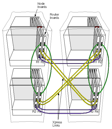
Figure 4-6 and Figure 4-7 show two examples of 32P (or processor) configurations. These systems require two racks, along with the necessary CrayLink Interconnect cabling. Each of the racks has two modules, and each module has four Node boards and two Router boards. This configuration simply doubles the 16P configuration by adding a second (16P) rack.
| Note: It is possible for a configuration to have between 4 and 32 processors. The 16P and 32P configurations are used because they represent the maximum number of processors for one- or two-rack systems. |
The configuration shown in Figure 4-7 uses Xpress links to increase the transmission throughput between modules and racks. The Xpress links provide additional data routing, which reduces potential transmission latency.
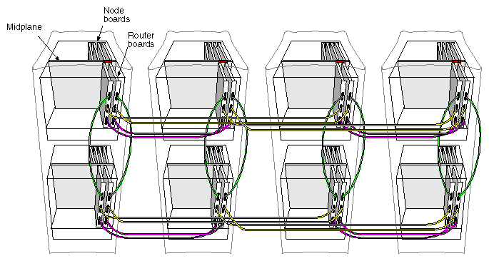
In Figure 4-7, all the available router ports are used. To go beyond a 32 processor configuration, the Xpress links must be removed and more CrayLink Interconnect cables must be installed. Figure 4-8 represents a 64P configuration which is simply a double of the previous 32P system.
This configuration consists of four racks, eight system modules, and 32 Node boards. As Figure 4-8 shows, all of the available Router ports are now in use. The 64P configuration is the largest one that can be supported using the Rack Router board. To go beyond 64P, requires the use of a meta router chassis. With a meta router, configurations of up to 128P are possible (see Figure 4-9).
