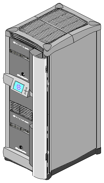
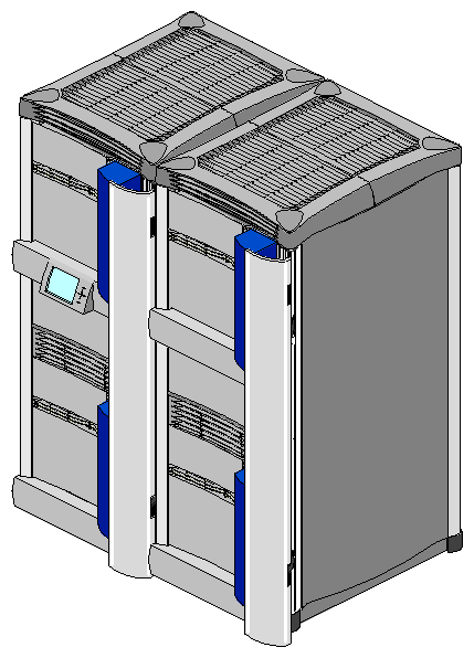
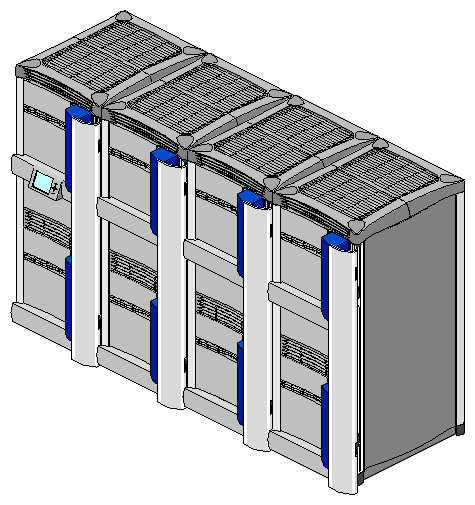
The Origin2000 rackmount system provides a highly configurable system architecture that is available in a single rackmount or multirack setup. The rackmount consists of 2 to 16 CPUs, 64 MB to 32 GB of main memory and can provide a wide variety of I/O interfaces (see Figure 1-1). The Origin2000 multiple rack (or multirack) configuration has up to 128 processors and up to 256 GB of main memory (see Figure 1-2 and Figure 1-3).
The Origin2000 is ideal for evolving applications requiring expansion capability as requirements grow. Some of the Origin2000 features include:
significantly lower entry system costs (with pay-as-you-grow expandability)
support of a large number of processors (up to 128)
high bandwidth I/O connectivity
higher total memory capacity (up to 256 GB of main memory)
optional connectivity to third-party peripheral connector interface (PCI) boards
superscalar R10000™ CPU (in the IP27 Node board) supports advanced memory latency tolerance features such as out-of-order execution and advanced branch prediction to address real-world application demands
large variety of peripheral connectivity options
XIO boards providing additional I/O, mass storage connections, and graphics capabilities
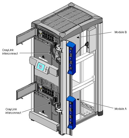
As shown in Figure 1-4, a single Origin2000 rackmount system can consist of two fully integrated and independent subsystems—Module A and Module B. Each of the modules in Figure 1-4 has a dedicated System Controller, which monitors module status. Each module can also have a separate set of hard disks, CPUs, I/O connections, and memory, as well as a separate operating system, and a separate set of applications.
The modules communicate using the high-speed (1600 MB/sec) CrayLink™ Interconnect link. The CrayLink Interconnect (also known as the interconnection fabric) link consists of a set of high-speed routing switches and cabling that enables multiple connections to take place simultaneously. Using the CrayLink Interconnect, hardware resources (including main memory) can be shared and accessed by other modules in the configuration. For more information on the CrayLink Interconnect see “CrayLink Interconnect”.
| Note: Not all rack system have two fully self-contained modules; some may have only one; some configurations may have as many as 16 modules. For more information on the different rack configurations, see Chapter 4, “System Configurations.” |
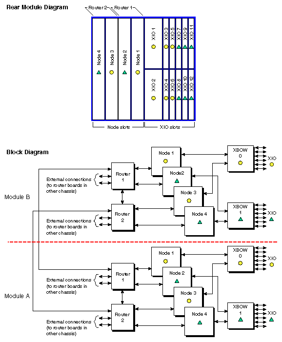
Figure 1-5 provides an overall block diagram of an Origin2000 rack system. The major hardware components include the:
IP27 Node board
Router board
BaseIO board
XIO slots
For a description of these components, see Chapter 2, “Chassis Tour.”
The rear module diagram shown in the top portion of Figure 1-5 appears in the back of the chassis between the Node boards and fan tray. This diagram provides a map that tells system installers where to install Node boards and XIO boards into the system. Use this diagram to help correspond the Node boards and XIO blocks in the block diagram to their actual physical location in the chassis. For more information on how to read this diagram, see “Board Configuration and Layout” in Chapter 2.
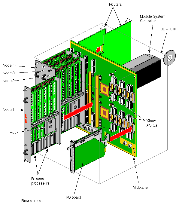
Figure 1-6 shows how some of the major hardware components connect inside a system module. All these components interface using a common midplane with connections made to both the front and the back.
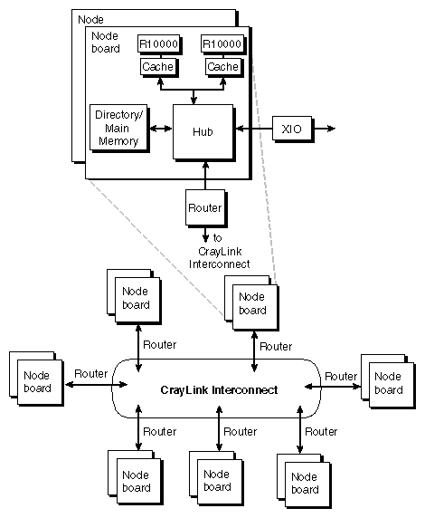
As illustrated in Figure 1-7, the Origin2000 is a number of processing modules linked together by the CrayLink Interconnect. Each processing module contains either one or two processors, a portion of main memory, a directory to maintain cache coherence, and two interfaces: one that connects to I/O devices and another that links system nodes through the CrayLink Interconnect.
Cache coherence is the ability to keep data consistent throughout a system. In the symmetrical multiprocessor (SMP) Origin2000 system, data can be copied and shared among all the processors and their caches. Moving data into a cache may cause the cached copy to become inconsistent with the same data stored elsewhere. The Origin2000 cache coherence protocol is designed to keep data consistent and to propagate the most recent version of the data to wherever it is being used.
The CrayLink Interconnect links modules to one another. The CrayLink Interconnect may appear to be a type of super data bus, but it differs from a bus in several important ways. A bus is a resource that can only be used by one processor at a time. The CrayLink Interconnect is a mesh of multiple, simultaneous, dynamically allocatable connections that are made from processor to processor as they are needed. This web of connections differs from a bus in the same way that multiple dimensions differ from a single dimension: if a bus is a one-dimensional line, then the CrayLink Interconnect is a multidimensional mesh.
The Origin2000 is also scalable - it can range in size from 2 to 128 processors. As you add modules, you add to and scale the system bandwidth. The Origin2000 is also modular, in that it can be increased in size by adding standard modules to the CrayLink Interconnect.
The Origin2000 architecture achieves this scalable processing power primarily by using the following technology:
CrayLink Interconnect
XIO slots
Distributed shared memory
new IRIX operating system
The Origin2000 modules are connected by the CrayLink Interconnect (also known as the interconnection fabric). The CrayLink Interconnect is a set of switches, called routers, that are linked by cables in various configurations, or topologies. Here are some key features that define the Origin 2000 interconnection fabric:
The CrayLink Interconnect is a mesh of multiple point-to-point links connected by the routing switches. These links and switches allow multiple transactions to occur simultaneously.
The links permit extremely fast switching (a peak rate of 1600 MB/sec bidirectionally, 1600 MB/sec in each direction).
The CrayLink Interconnect does not require arbitration, nor is it limited by contention.
More routers and links are added as nodes are added, increasing the CrayLink Interconnect's bandwidth.
The CrayLink Interconnect provides a minimum of two separate paths to every pair of Origin2000 modules. This redundancy allows the system to bypass failed routers or broken fabric links. Each fabric link is additionally protected by a CRC code and a link-level protocol, which retry any corrupted transmissions and provide fault tolerance for transient errors.
The XIO cardcage allows you to install additional I/O type boards (such as ultra-SCSI, fibre channel, FDDI, and graphics interface) into the Origin2000 chassis. In addition, an optional PCI carrier assembly allows users to install up to three PCI boards into the Origin2000 base module. XIO uses the same physical link technology as the CrayLink Interconnect, but uses a protocol optimized for I/O traffic.
The XIO features are:
high bandwidth—1600 MB/sec (peak)
concurrent transfers
real-time performance
future expandability
The Origin2000 employs a distributed shared memory system architecture where main memory is split among the Node boards. Rather than appearing as one fast memory, main memory is “distributed” over the configuration, with a little piece of the memory near each processor. Thus the name “distributed shared memory.” A directory memory keeps track of information necessary for hardware coherency and protection.
This differs from previous-generation Silicon Graphics systems, in which memory is centrally located on and only accessible over a single shared bus. By distributing the Origin2000 memory among processors, memory latency is reduced. Accessing memory near a processor takes less time than accessing remote memory. Although physically distributed, all of main memory is available to all processors.
The Origin2000 memory is located in a single shared address space. Memory within this space is distributed amongst all the processors, and is accessible over the CrayLink Interconnect. I/O devices are also distributed within a shared address space; every I/O device is universally accessible throughout the system.
The new 64-bit IRIX operating system is based on UNIX System V, Release 4, distributed software technology. IRIX supports modular computing, providing availability and throughput on small, one-to-four processor systems. It also supports scalability, performance, resilience, and throughput on large systems with tens or hundreds of processors and hundreds of gigabytes of memory.
