When your Origin2000 deskside system is initially set up in the work area, a trained system support engineering (SSE) technician should configure and connect it.
Your Origin2000 deskside system is fully functional as a standalone server using Ethernet, modem, optional ATM, HIPPI, or other interconnect technologies.
Proper configuration and interconnection of any optional XIO interconnect cables or hardware can be accomplished by the SSE at initial system installation or when an upgrade is ordered.
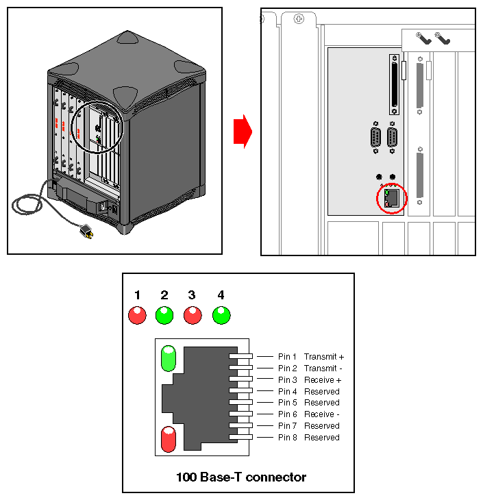
The system comes standard with a single 100 Base-T 8-pin Ethernet connector. Optional boards supporting additional Ethernet connectors are available.
Table 4-1 shows the cable pinout assignments for the Ethernet 100 Base-T Ethernet port.
Table 4-1. Ethernet 100-BASE T Ethernet Port Pin Assignments
Pin | Assignment |
|---|---|
1 | TRANSMIT+ |
2 | TRANSMIT– |
3 | RECEIVE+ |
4 | (Reserved) |
5 | (Reserved) |
6 | RECEIVE– |
7 | (Reserved) |
8 | (Reserved) |
Figure 4-1 shows the location of the standard Ethernet connector on the deskside system.
There are two LEDs on the RJ-45 Ethernet; the top (green) LED lights only when the system is transmitting. The bottom (yellow) LED lights whenever it sees any packet on the wire. This includes packets not destined for your system.
Just above the RJ-45 Ethernet connector is a set of four LEDs. They have the following functions:
The yellow LED on the far left (LED 1) lights to indicate SCSI activity on the BaseIO single-ended SCSI connector.
The green LED (LED 2) lights to indicate 100 Mb-per-second packet activity.
The yellow LED on the right (LED 3) indicates when the Ethernet is operating at full duplex rates of transfer or receive.
The rightmost green LED (LED 4) shows the Ethernet link test. It lights when linkstate is valid.
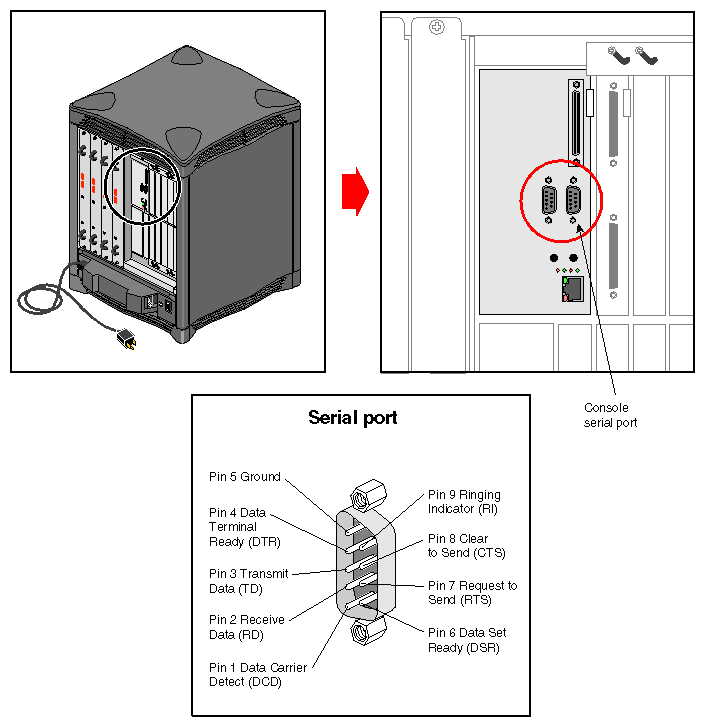
Each Origin2000 deskside system comes with two standard 9-pin serial ports. These ports can support either RS-232 or RS-422 interface devices. Figure 4-2 shows the location and pinouts for a serial port. Optional additional serial ports are also available for your system.
| Note: You cannot use serial cables that work with older Silicon Graphics deskside systems on the Origin2000 deskside. |
The RS-232 standard recommends the use of cables no longer than 50 feet (15.2 meters). This standard should also be applied to the RS-422 connector. Longer runs introduce a greater possibility of line noise occurring. This can affect data transmission and cause errors. For cable runs longer than 50 feet (15.2 meters), use an appropriate extender device.
| Note: Do not run cables through areas that are electrically noisy, such as areas where large electric motors, welding apparatus, or X-ray machines operate. Bury outside wiring in conduit, as lighting strikes can damage the system. |
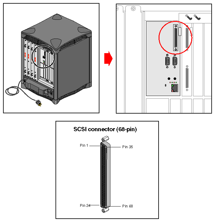
A single external 68-pin SCSI connector is provided on the BaseIO panel. This connector supports both Ultra SCSI and SCSI-2 devices. The connector sends single-ended SCSI signals only.
Optional additional SCSI ports can be implemented using Silicon Graphics XIO option boards.
The hyphen preceding a signal name indicates that the signal is low. Note that 8-bit devices that connect to the P-cable leave these signals open: -DB(8), -DB(9), -DB(10), -DB(11), -DB(12), -DB(13), -DB(14), -DB(15), -DB(P1). All other signals are connected as shown in Table 4-2.
Table 4-2. 68-Pin Single-Ended, High-Density SCSI Pinouts
Signal Name | Pin Number | Pin Number | Signal Name |
|---|---|---|---|
Ground | 1 | 35 | -DB(12) |
Ground | 2 | 36 | -DB(13) |
Ground | 3 | 37 | -DB(14) |
Ground | 4 | 38 | -DB(15) |
Ground | 5 | 39 | -DB(P1) |
Ground | 6 | 40 | -DB(0) |
Ground | 7 | 41 | -DB(1) |
Ground | 8 | 42 | -DB(2) |
Ground | 9 | 43 | -DB(3) |
Ground | 10 | 44 | -DB(4) |
Ground | 11 | 45 | -DB(5) |
Ground | 12 | 46 | -DB(6) |
Ground | 13 | 47 | -DB(7) |
Ground | 14 | 48 | -DB(P) |
Ground | 15 | 49 | Ground |
Ground | 16 | 50 | Ground |
TERMPWR | 17 | 51 | TERMPWR |
TERMPWR | 18 | 52 | TERMPWR |
Reserved | 19 | 53 | Reserved |
Ground | 20 | 54 | Ground |
Ground | 21 | 55 | -ATN |
Ground | 22 | 56 | Ground |
Ground | 23 | 57 | -BSY |
Ground | 24 | 58 | -ACK |
Ground | 25 | 59 | -RST |
Ground | 26 | 60 | -MSG |
Ground | 27 | 61 | -SEL |
Ground | 28 | 62 | -C/D |
Ground | 29 | 63 | -REQ |
Ground | 30 | 64 | -I/O |
Ground | 31 | 65 | -DB(8) |
Ground | 32 | 66 | -DB(9) |
Ground | 33 | 67 | -DB(10) |
Ground | 34 | 68 | -DB(11) |


