The Encoder channel, which can take the place of Channel 1, encodes its own or another channel's pixels to NTSC or PAL television standard for industrial-quality video out via the RCA and BNC connectors for NTSC and PAL or the S-Video connector on the InfiniteReality I/O panel.
The Encoder channel can encompass an entire video channel, allowing whole-screen recording without an external scan converter. For video formats with pixel clock rates above 120 MHz, the Encoder works in pass-through mode, allowing you to record a pannable NTSC- or PAL-sized region of the display.
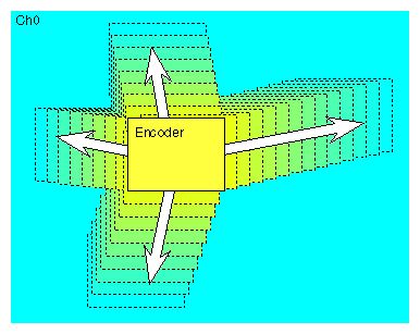
Alternatively, to save bandwidth, the Encoder channel can take a source channel's pixels and encode them. The Encoder channel samples the source channel's pixels at a point in the channel rectangle that you determine and encodes them to the standard you choose. Figure 3-1 diagrams a roaming Encoder whose source is Channel 0.
Flexible, built-in video resampling allows the Encoder to process any rectangular area of any video channel, up to and including the full screen. Also, applications can be recorded even if they were not written with NTSC or PAL resolution in mind. The Encoder handles without distortion video formats that have aspect ratios other than the 3:4 aspect ratio of NTSC or PAL.
This chapter explains
The Encoder channel can be set up in independent mode or dependent mode.
In the Encoder Attributes window, select None in the Source Channel popup menu to set up the Encoder channel in independent mode. In this mode, pixels coming to the Encoder channel are 10 bits.
Like other channels, the Encoder in independent mode consumes pixel bandwidth. The Combiner validates the selection along with the other channels.
For dependent mode, select a specific channel in the Source Channel popup menu on which the Encoder is to be dependent. In this mode, a portion of the visible surface from one of the other high-resolution channels (as selected in the Source Channel popup menu) is sent to the Encoder for video out.
If the size of the selected region matches the size of the output format, the Encoder uses a precision of 10 bits per component and does not process the pixels (pass-through mode). However, if you have enlarged the input size so that it is larger than the output size of the format, pixels are filtered and processed to fit the output size (reduced mode). Filtered pixels have a precision of 8 bits per component.
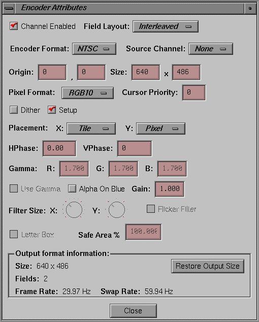
To view or change attributes of the Encoder channel, select the channel rectangle and select “Edit attributes...” in the Channel menu. The Encoder Attributes window appears, as shown in Figure 3-2.
Largely, this window shares features of the Channel Attributes window. See for explanations of these features. Features this window does not share with the Channel Attributes window are the Letter Box toggle and the Safe Area percentage choice, which are explained in this section.
This section explains
Output resolution (Encoder Format in the Encoder Attributes window) is fixed to NTSC or PAL square-pixel formats:
NTSC: 646 x 486
PAL: 768 x 576
| Note: The composite and S-Video Encoder outputs are for industrial or monitoring purposes only and are not designed for broadcast television use. For broadcast-quality composite video, configure a video channel of the graphics system as RS-170 or Euro 625 resolution and send it through an external broadcast-quality encoder. For CCIR601 or broadcast-quality component video, use the Sirius Video option, as explained in Chapter 4. |
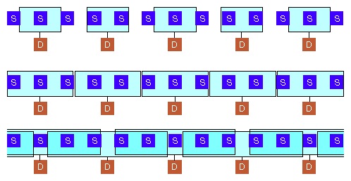
In the Encoder and Sirius Video Attributes window, use the Filter Size dials to set filter size in the X and Y directions for video resampling. The ticks at the dials correspond to the number of source pixels used to derive the destination pixels. As you adjust the dials, view the changes on an output monitor to determine the desired filter size.
Figure 3-3 diagrams variations of the filter width; in this figure, S = source pixel and D = destination pixel (after the filter is applied). The wider the filter, the more blurred the output image.
In Figure 3-3:
first row: the filter does not sample all source pixels to yield the destination pixels
second row: the filter samples all source pixels
third row: the filter samples several pixels to yield each destination pixel, overlapping the source pixels sampled
| Note: Scaling is better done in the Y direction, where any resultant fuzziness is less noticeable, than in the X direction. |
The Safe Area is the area of the output raster in which the picture is placed. At a Safe Area setting of 100%, the usual setting, the active picture fills the active area of the raster.
Consumer TV receivers are normally overscanned, with roughly 5% of each edge hidden behind the monitor's cabinet. To set the Encoder to place the image inside this area, set the Safe Area to 90%; this setting puts the image into the central 90% of the active area of the raster.
Letterboxing is preserving the aspect ratio of the source. For example, if you are using a 1280 x 486 area of your main screen for the Encoder channel in dependent mode and Letter Box is not checked, the 1280 x 486 is scaled down to the 646 x 486 Encoder output, distorting the X direction. If Letter Box is checked, X and Y are scaled equally: 1280 is scaled to 646 (a ratio of 1280:646, or 1.98:1) and 486 is scaled the same percentage, resulting in 246 scan lines.
These 246 scan lines are placed in the middle of the Encoder output: the 486 output lines consist of 120 black lines at the top, the 246 active lines, and 120 black lines at the bottom.


