This chapter explains how to use the Video Format Combiner GUI to create and set video format combinations, in these sections:
To display the Combiner's graphical user interface, type
/usr/gfx/ircombine -gui |
To specify a different display from the current workstation, such as a different pipe of a rackmount system, a remote workstation, or a specific pipe of a remote rackmount system as the target on which to display the combination, use
/usr/gfx/ircombine -gui -target displayname |
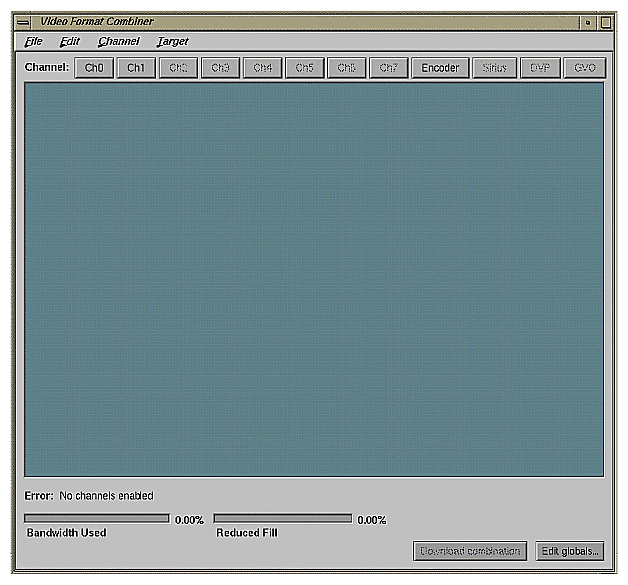
Figure 2-1 shows the main window.
The managed area is the display surface taking up most of the Combiner main window. It represents the entire raster (framebuffer area); all channels derive their pixels from areas on the raster. The managed area can be redefined.
The Bandwidth Used scale indicates the percentage of the communication bandwidth between the framebuffer and the video subsystem that the combination is using. In general, as long as the bandwidth used is less than 100 percent, things are fine. However, the bandwidth used is related to the framebuffer memory used to refresh the video channels, which the Reduced Fill scale shows.
The Bandwidth Used scale is affected by
the size of each channel (its footprint on the framebuffer, not its output resolution, although the two are related)
the Pixel Output Format selected in the channel attribute window; to save bandwidth, avoid choosing 10-bit components and alpha
the number of video channels
the Encoder channel being set up in independent mode; dependent mode does not use any extra bandwidth or fill rate
Adding RM boards does not increase the video bandwidth available in the system.
The Reduced Fill scale indicates the percentage of framebuffer memory cycles used for refreshing the video channels of the combination. In general, reduce the pixel-fill specifications of the framebuffer by this percentage. If the application still meets its spec for depth complexity, number of polygons, and so on when the fill rate of the framebuffer is reduced by the percentage indicated by the Reduced Fill scale, things are fine.
Adding RM boards amortizes the video-refresh overhead over more boards, so it helps to add RM boards if the video refresh overhead is too high for a particular hardware configuration and application. The Reduced Fill scale is affected by the same factors as the Bandwidth Used scale.
If system constraints are violated, the Error indicator displays a message; see Appendix B, “Error Messages.”error messages in the InfiniteReality Video Format Combiner User's Guide. The Error indicator shows <none> for a valid video format combination.
The Combiner software includes sample video format combinations in /usr/gfx/ucode/KONA/dg4/cmb. To load one of these or any other combination:
from the Combiner main window, do one of the following:
at the IRIX command prompt, do one of the following:
As you build your own combination, you can test it by saving it, downloading it, adjusting, saving, and downloading it again, until you are satisfied.
When you initialize InfiniteReality graphics, or power on the system with InfiniteReality graphics installed, you can load a previously saved combination, as described above, or use the Combiner to define the video output for the Onyx InfiniteReality workstation, regardless of the number of channels you use.
To initialize graphics, enter the following; the parentheses are necessary.
(/usr/gfx/stopgfx ; /usr/gfx/startgfx) & |
This section explains
In the Combiner main window, click the button for the channel you want to define; for example, Ch0 for the first channel. This selection corresponds to Chan0 on the InfiniteReality I/O panel.
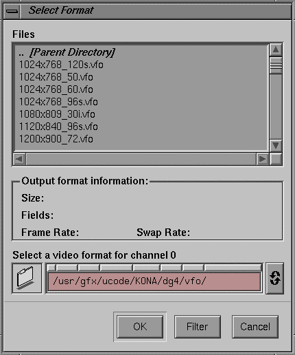
When you click a channel button, the Select Format window appears, as shown in Figure 2-2; select a video format for the channel. This window conveniently displays basic information about the format you select. (For more information on the video formats stored in the files, consult /usr/gfx/ucode/KONA/dg4/vfo/README.)
| Note: If your system includes channels 2 through 7, assign the formats with the highest bandwidth to Channels 0 and 1, because they have greater capability. For more information, see “DAC Output Bandwidth”. |
You can easily resize the rectangle with the mouse or by editing channel attributes, as explained in “Resizing and Repositioning a Channel”. The dimensions of the format (for example, 1920 x 1200 for the format file 1920x1200_60.vfo) are the output dimensions, but need not be the input dimensions of the channel's rectangle in the managed area. You can also use the Video Format Compiler to create your own formats.
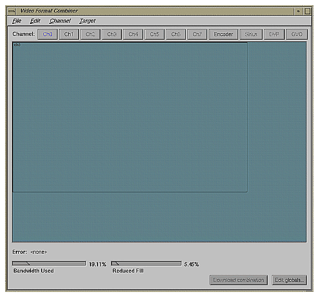
Figure 2-3 shows the Combiner main window with Channel 0 defined. The channel's rectangle appears in the managed area.
Notice that the Bandwidth Used scale indicates that some of the video subsystem is now in use.
The channel rectangle shows the area on the raster from which Channel 0 derives its pixels.
To change the size and position of the channel in the managed area, use the mouse to move the channel rectangle. Dragging the rectangle changes the channel's origin; dragging one of the handles at a corner resizes the channel. You can also use h, j, k, or l as arrow keys to move the sides of the rectangle, as summarized in Table 2-1.
Table 2-1. Resizing and Repositioning
Key | Action |
|---|---|
h | Moves channel rectangle to the left |
l | Moves channel rectangle to the right |
j | Moves channel rectangle down |
k | Moves channel rectangle up |
Ctrl + h | Decreases channel rectangle's width |
Ctrl + l | Increases channel rectangle's width |
Ctrl + j | Increases channel rectangle's height |
Ctrl + k | Decreases channel rectangle's height |
For pixel-accurate positioning and sizing, edit the channel's origin and size, as explained in “Origin and Size”.
To copy an existing channel format—size, origin, and other characteristics—to a new channel, follow these steps:
Click the button of the new channel (for example, Ch3); in the Files window, select any video format.
Select the rectangle of the channel you want to copy (for example, Ch0). Select “Copy” in the Edit menu, or press Ctrl + c.
Select the rectangle of the new channel. Select “Paste” in the Edit menu, or press Ctrl + v.
To create a new channel that contains all the attributes of an existing channel, just follow steps 2 and 3 above. The next unassigned channel in sequence is assigned; for example, if you are copying Channel 0 and the remaining channels on the system are undefined, the Combiner assigns its format to Channel 1. The new channel appears at the same origin as the copied channel; move it if desired.
To align channels exactly, edit their origin and size, as explained in “Origin and Size”. To use a convenience feature of Combiner to expedite this procedure, follow these steps:
In the managed area, move the channel rectangles to approximately where you want them.
Select a channel rectangle; select “Snap to neighbor” in the Channel menu. The channel corners align with those of the closest neighboring channel.
If necessary, refine the channel's origin and size settings, as explained in “Origin and Size”.
The Combiner includes a convenience feature for associating a video channel with an open X window. You can position and size the video channel's rectangle in the managed area to correspond to the X window's position. To use an X-server window as input for the origin and size of a channel, follow these steps:
Make sure the window you want to use as input for the channel is where you want it on the screen.
In the Combiner main window, select the rectangle of the channel with which you want to associate the X window.
Select “Grab window...” in the Channel menu. A crosshatch cursor appears.
Move the crosshatch cursor to the window you want to use as input for the channel and click the left or right mouse button.
The Combiner uses that X window's origin and size as the position of the channel.
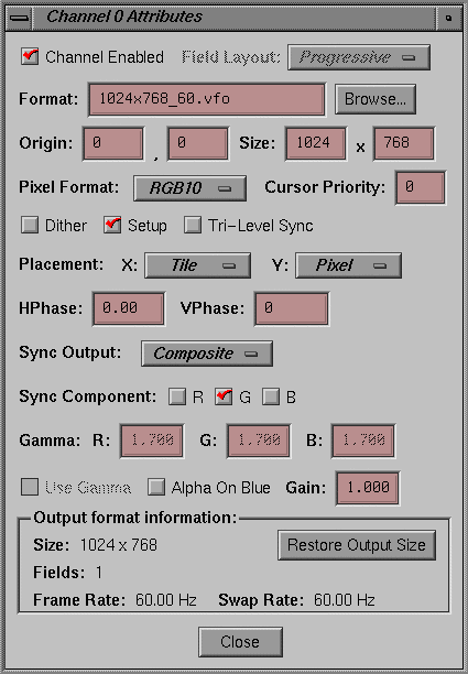
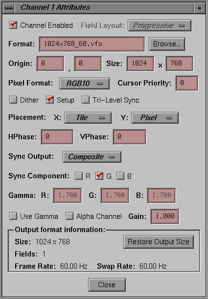
Select the channel for which you want to view or modify attributes, and select “Edit attributes...” in the Channel menu. (You can also double-click on the channel's button or rectangle.) The channel window appears; Figure 2-4 shows an example.
| Note: You can also access the Channel menu by pressing the right mouse button. |
A box at the bottom of this window displays format information stored in the video output file selected for this channel. If you resize the rectangle, click Restore Output Size to restore it to the size specified in the output file. The output pixel format is unrelated to the underlying framebuffer organization because the InfiniteReality hardware automatically converts to the output pixel format you request.
| Note: For a combination to be valid, the swap rates of all channels, including any option board present, must be the same. The swap rate is shown near the bottom of the Channel Attributes window. As you add channels to the managed area to create a combination, keep track of the swap rates. For more information on the swap rate, see “Swap Rate”. |
This section explains how to use fields in this window.
The field layouts are designed to allow you to reduce fill, rendering only the visible lines of each field of an interlaced format. The Combiner attempts to set the correct field layout for each video format automatically.
Use the Field Layout popup menu to select the order in which data is fetched (scanned) from the framebuffer:
Progressive: specifies sequential data fetching: each field draws from the entire source region of the channel. This setting is the default for formats with one field.
Interleaved: specifies a two-field format: the lines of the fields are vertically interleaved in the framebuffer.
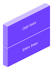
Stacked: specifies a two-field format. The lines of each field are contiguous; the lines of the first field occupy the top half of the framebuffer, and the lines of the second field occupy the bottom half, as diagrammed in Figure 2-5. Use this choice to render the even and odd fields separately for a pixel-fill advantage.
The text field displays the name of the file containing the video format on this channel. To change the currently selected format for the channel, type a different .vfo filename in the text field, or click Browse and select a different one in the popup menu.
To change the video format for a channel, follow these steps:
Select the channel rectangle.
Press the right mouse button; in the menu that appears, select “New channel.” The Select Format window appears.
In the Select Format scrolling list, choose another video output format.
The Origin and Size fields display values for the current video format in the window; these settings define the mapping, or footprint, of the channel in the framebuffer managed area. You can change these values here as well as by manipulating the rectangle with the mouse.
Use the choices in the Pixel Format popup menu to select the output pixel format for this channel:
| Note: For Sirius Video, make sure that the Alpha Channel check box is unchecked. |
RGB10: 10-bit RGB with no alpha (this setting is the default); use this setting to save bandwidth when alpha is not required
-
Only the Sirius Video option is capable of outputting this format.
If this format is selected for a channel other than Sirius Video, the channel outputs 10-bit RGB. However, if alpha is enabled (see “Alpha On Blue”), 10-bit alpha is output as blue. This setting is useful for outputting alpha on a dedicated channel.
Z: 24-bit Z component
Each pixel's z-buffer values are sent instead of its RGB values. This format is useful for “virtual set” applications. A pair of video channels is mapped to the same region of the framebuffer. One channel is set up to get RGB, and the second channel is set up to get Z. The Z component is used as a mask for putting live actors “into” the virtual set.
FS: color field sequential for special monitors that expect color fields in a particular sequence
Check this box to dither the output of this channel by default.
Because the pixel output format might be different from the framebuffer color storage format, the InfiniteReality subsystem must know which method to use to adapt the framebuffer contents to the output format. For example, the framebuffer might contain 12-bit RGB, although you have selected the Pixel Format RGB10 to send to the video subsystem. If Dither is not selected, the system truncates the colors. Selecting Dither causes the system to add a fixed pattern of noise to the colors before it truncates them.
Check this box to enable pedestal (an artificial black-level voltage) for this output (disabled by default). Make sure this box is unchecked (setup disabled) for PAL and for Japanese NTSC.
Setup (also called pedestal) is typically used in NTSC and is typically not used in PAL. Setup is the difference between the blanking level and the blackest level displayed on the monitor. A black level that is elevated to 7.5 IRE instead of being left at 0.0 IRE is the same as the lowest level for active video. Because the video level is known, this part of the signal is used for black-level clamping-circuit operation.
Check this box to enable trilevel sync for separate RGB ports. This selection is useful for enabling trilevel sync for HDTV monitors that use trilevel sync. You cannot have trilevel sync on CSYNC output (the H/C sync port).
The cursor is visible on only one channel at a time. If your video format combination includes overlapping rectangles, you can set cursor priority to determine which channel displays the cursor when it enters a region where the channels overlap.
To set cursor priority for a channel, enter a number between 0 and 255, with lower numbers indicating higher priority.
If you set the same priority number for more than one channel in the combination, the channel that last displayed the cursor retains it. If the cursor did not previously appear in either of the contending channels, the channel with the lower channel number displays the cursor.
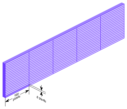
The framebuffer is divided into individually addressable tiles 160 pixels wide and 8 pixels high; see Figure 2-6. With each line, entire tiles in the horizontal direction are transferred, not portions of them.
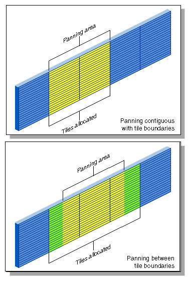
If panning is locked to tile boundaries, less bandwidth is used (as shown in the bandwidth scale in the lower left of the Combiner main window). If you choose to pan on a per-pixel basis, the Combiner must account for an extra tile in the horizontal direction. Because more tiles are transferred for every line, the result is some wasted bandwidth; Figure 2-7 diagrams this contrast. During run time, smooth per-pixel panning costs extra bandwidth as well; see the discussion in “Changing Global Attributes for Combinations”.
The choices in the X and Y popup menus at Placement specify the relationship between the panning area and the number of tiles transferred:
Locked: This choice prevents the user from panning in this direction during run time.
Pixel: Framebuffer use is on a per-pixel basis, allowing run-time panning that is not aligned to tile boundaries. This setting is the default for the Y direction.
Tile (X direction only): This choice allocates framebuffer use by entire tile and restricts run-time panning to tile boundaries as well. This setting is the default for the X direction.
The horizontal and vertical phase settings apply only if the channel is genlocked to external sync. The settings line up the pixels in two video streams.
Use the HPhase field to enter a floating point number as the default horizontal phase value for this channel. Positive values delay the genlocked video channel with respect to external sync, and negative values advance the genlocked video channel with respect to sync. The default is 0.
Use the VPhase field to enter the default vertical phase value for this channel. This value ranges from 0 to the number of lines in the video format minus 1. The default value is 0.
In addition to composite sync on green, InfiniteReality provides separate horizontal and vertical video signals for compatibility with a wide variety of video equipment such as projectors and recorders.
| Note: For locations of the physical connectors on the Onyx and Onyx2 graphics I/O boards, see the owner's guide of the respective workstation. |
Make a choice in the Sync Output popup menu to set the output for the alternate sync port:
Horizontal: put horizontal sync on the H/C Sync port
Composite: put composite sync on the H/C Sync port (this setting is the default)
Use the check boxes at Sync Component to specify whether the R, G, and B components have sync enabled by default.
The brightness characteristic of a monitor's CRT is not linear with respect to voltage; the voltage-to-intensity characteristic is usually close to a power of 2.2. If left uncorrected, the resulting display has too much contrast; detail in black regions is not reproduced. To correct this inconsistency, a gamma value (correction factor) using the 2.2 root of the input signal is available so that equal steps of brightness or intensity at the input are reproduced with equal steps of intensity at the display.
If your InfiniteReality system has two channels, it uses one gamma table for both channels. You can change the output video gamma values from the factory setting of 1.700 for the red, blue, or green components; these values apply to both channels. The gamma for all channels derives from the same gamma map, gamma map 0.
If your InfiniteReality system has eight channels, you can change the output video gamma values for the red, blue, or green components for each channel separately. Follow these steps:
Click Edit Globals... at the lower right of the main window. The Combination Attributes window appears, as shown in Figure 2-8. (Details of this window are discussed in “Changing Global Attributes for Combinations”.)
Unselect the Global Gamma check box at the lower left and close the window.
In the Channel Attributes window for the channel whose gamma values you want to change, select the check box at Use Gamma, as shown in Figure 2-9.
Enter the gamma values for R, G, and B.
Repeat this process for other channels for which you want custom gamma values.
Check the check box at Alpha On Blue to produce the alpha component of the input channel instead of blue component from the framebuffer. For this setting to be in effect, the RGBA10 pixel format must be selected, as explained in “Pixel Format”.
When you check this box, gamma correction is disabled for this channel; alpha is never gamma-corrected.
Most modern video postproduction equipment, such as the Sirius Video option, uses alpha in digital form. For compatibility with older equipment that requires analog alpha, you can use a second channel.
To set up a dedicated channel for alpha out, follow these steps:
On the equipment you are using to output analog alpha, hook up to the blue component out; on the alpha channel, the blue component is replaced with 10-bit alpha.
Make sure both channels are running the same video format and are positioned and sized identically in the framebuffer managed area. (If you are setting up the channels at this time, you can use the Copy feature as explained in “Copying a Channel”.)
In the Channel Attributes window of the channel you want to use for analog alpha, make sure the Alpha On Blue check box is checked to enable alpha. Make sure it is unchecked in the other channel's Channel Attributes window.
In the Pixel Format popup menu, select the format RGBA10 for each channel.
In the text field at Gain, you can change the default output video gain value for this channel from 1.0 to a value between 0.0 and 10.0. The system software forces the value you enter to the closest gain that is physically realizable on the output channel.
Normally, gain is set to a midrange level, such as 6.0. At this value, peak white equals 700 mV.
When you save a combination, the video formats on all channels defined in the Combiner main window are included in the combination by default.
To delete a channel from a combination, select its rectangle in the Combiner main window and press Delete or Ctrl + x.
For test purposes, you can keep the definition of the channel in the combination while disabling the channel output (and thus saving the bandwidth that the channel would consume). To do so, make sure the Channel Enabled check box is unchecked (disabled).
For information on setting cursor priority for overlapping channels, see “Tri-Level Sync”.
For the combination to be valid, check the following:
Make sure that the swap rates of all channels match, including the Sirius Video channel. The swap rate is shown in each Channel Attributes window. For more information on the swap rate, see “Swap Rate”.
Make sure that the Error indicator in the main Combiner window indicates <none>.
| Note: The Combiner can write invalid combinations so that they can be loaded and worked on in another session. |
You can use the setmon utility to download saved combinations, as indicated in “Downloading a Video Format Combination”; however, setmon rejects invalid combinations. See the setmon reference page for details.
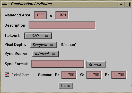
To change attributes such as pixel depth, gamma values, sync source, and sync format for all combinations at once, click Edit Globals. Figure 2-10 shows the Combination Attributes window.
The numerals displayed in the Managed Area fields show the dimensions of the framebuffer, which is managed by the X Windows server. Note that allocation of the framebuffer is on a tile basis; if you allocate the framebuffer in units other than whole tiles (160-by-8-pixel boundaries), pixels are inaccessible.
If the video output format has a width of 1280 pixels, exactly eight tiles (160 x 8 = 1280) are allocated. If you specify a width of 1281 pixels in the Size field or with the mouse, the Combiner still transfers nine tiles, though the ninth tile is barely used.
The Combiner always shows the allocated area to make it clear that memory is being made inaccessible if the managed area size differs from that of the allocated area. When allocation and managed area size differ, a vertical or horizontal red line (or both) appears in the Combiner window dividing the managed area (left of or above the line) from the unusable portion of the allocated area (right of or below the line).
In general, it is best to put the managed area on the channel boundaries, even if doing so makes part of a tile inaccessible. The X Window System never moves the cursor outside the managed area, so making the managed area follow the borders of the video channels makes it harder to lose the cursor by moving it “off-screen.”
When you save the formats as a video output combination, the extra bandwidth that the Combiner allocated (see “Channel Placement in the Framebuffer”) is accounted for, even though the channel might be placed on a tile boundary at that time. The Combiner accounts in advance for the worst-case bandwidth that can occur at run time when the user smoothly pans the channel.
To add a description of up to 256 characters to the file that stores the combination, enter it in the Description text field.
This section explains
selecting a channel for textport output
setting pixel depth
setting gamma values
setting sync source and format
In the Textport popup menu, select the channel to be used as the textport output. This channel displays boot information when the workstation is restarted.
Pixel depth specifies the framebuffer pixel depth that this combination allocates when graphics are restarted with the combination that has been saved to the EEPROM, either from a system boot or manually with (/usr/gfx/stopgfx ; /usr/gfx/startgfx)&.
Use the Pixel Depth popup menu choices to set the arrangement of pixels in the framebuffer. The amount of memory in the framebuffer is constant, but its arrangement into pixels is flexible. In this context, the framebuffer can be thought of as a mass of clay. The total mass is fixed, but its arrangement can vary: it can be stretched out wide and broad, but shallow, or formed to be narrow, tall, and deep, as diagrammed in Figure 2-11.
Small, Medium, Large, and X–Large: set pixel depth as indicated by these names and allocate the framebuffer accordingly. Use this choice if pixel depth is more important to your application than the size of the managed area.
Deepest: instructs the Combiner to select the deepest possible setting for this managed area on this hardware configuration, where X–Large is the deepest, followed by Large, then Medium, and finally Small. Use this choice if the size of the managed area is more important to your application than pixel depth. This setting is the default.
For example, if you set pixel depth to Small, less framebuffer memory is used, but the shallow pixel depth results in fewer bits per pixel. Setting pixel depth to X–Large results in more bits per pixel, at the expense of the X,Y dimensions of the managed area. The X-Large setting provides richer information per pixel, which is useful for multisampling or other applications, and also provides more depth for stencil and z-buffering.
Deeper pixels cost a slight premium in rendering bandwidth and video bandwidth. Although framebuffer pixel depth has less impact on video bandwidth than the output pixel format (RGB10, RGB12, and so on), if speed is a concern, you can gain a slight advantage by selecting Small. In most cases, pixel depth is determined by the rendering features required, such as antialiasing, precision of the Z buffer, stencil buffer, and so on, rather than by video bandwidth considerations.
If you use one of these depth settings and then change the combination without restarting graphics, the depth setting is not guarantee because graphics must restart to accommodate the change in depth. In this case, the system software converts the setting to the current pixel depth without notice.
Also, if the system configuration does not support your choice when you restart graphics (for example, not enough RM boards), the configuration fails and the system software uses the Emergency Backup Combination (see “Emergency Backup Combination”). The actual pixel depth setting appears in parentheses beside the Pixel Depth popup menu; in the example in Figure 2-10, this value is Small.
For more information on setting pixel depth, see “Framebuffer Memory and Read/Write Bandwidth”.
If this check box is selected, the values shown for R, G, and B apply to all channels in the combination. If your InfiniteReality system has eight channels, you can set gamma values separately for each channel. For instructions and more information on gamma, see “Gamma”.
At Sync Source, select the InfiniteReality internal sync (Internal) or an external source that is connected to the Genlock In port.
In the Sync Format text field, enter the name of the video format file that describes the format to which to lock the video subsystem. If you do not specify an input genlock format, the video format of the combination's lowest-numbered channel with a valid sync signal is used. Click Browse to select a sync format contained in a file. You can create your own sync format file using the Video Format Compiler.
Using “Save” in the File menu saves the combination. If you have saved the combination previously, use “Save as...” to save the combination under a different filename.
To save a combination as the default file that is loaded the next time you initialize graphics or power on the system, save it to the EEPROM; select “Save to EEPROM...” in the File menu or enter setmon -x filename.
The combination saved to the EEPROM does not take effect immediately but is used the next time graphics is initialized, the system is powered on, or ircombine is run with the EEPROM as source and the current configuration as destination.
To add a description (256 characters or less) of the combination to the file, use the Description field in the Combination Attributes window, as explained in “Changing Global Attributes for Combinations”.
As you build your own combination, you can test it by saving it, downloading it, adjusting, saving, and downloading it again, until you are satisfied. To “test” it on different equipment, follow the instructions in “Using the Target Hardware Facility.”
| Note: To save the combination in the directory /usr/gfx/ucode/KONA/dg4/cmb, you must be running ircombine as superuser, or the system administrator must change permissions on that directory to allow writing to it. |
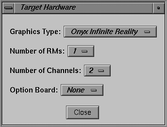
The Combiner includes a utility that lets you validate the combination using a hardware configuration you design. For example, if an error message appears indicating that the combination is too large for the hardware, you can use this Combiner facility to define a hardware configuration with more RM boards for test purposes.
This feature also allows you to run ircombine on other Silicon Graphics hardware to select the InfiniteReality hardware configuration most appropriate for a particular application. You can create valid combinations this way and later download them with ircombine or setmon onto InfiniteReality hardware configurations that meet or exceed the specifications you selected in the Target Hardware window.
In the Target menu, select “Edit user-defined hardware...” The Target Hardware window appears, as shown in Figure 2-12.
You can choose
Click Close to apply the settings to the combination.
