To render a curve or surface, you must develop an approximation of it with pfGeoSets. The tool that translates these reps into a mesh of contiguous triangles is called a tessellator.
Tessellation is interpretive; there is necessarily a difference between the original surface and the tessellated mesh. You can control how closely you want the mesh to resemble the surface.
Close resemblance, requiring many triangles, produces a realistic shape but incurs slow graphic processing.
A gross approximation of the original surface results in fast processing.
Applications often create a series of tessellated representations of a shape, each one called a level of detail (LOD). High resolution LODs are used when shapes are close to the viewer and low resolution LODs are used when shapes are far from the viewer. Because distance obscures detail, high resolution LODs are not necessary to represent distant shapes.
This chapter describes how to control the tessellation of shapes in the following sections:
Tessellators generate a sequence of straight-line segments to approximate an edge curve of a surface, then cover the surface with triangular tiles. With each triangle vertex it creates, a tessellator also stores the normal vector at the point from original surface. The normal vectors are necessary for lighting and shading calculations.
Tessellations necessarily burden the entire graphics pipeline; they provide a first definition of the rendering task by specifying a maximal set of vertices to be sent to the graphics hardware.
Ideally, you would quickly generate the simplest tessellation that adequately represents surfaces of interest. What is adequate depends on your particular rendering task. You may want to generate several tessellations with varying degrees of complexity and accuracy for one pfRep and place them in level-of-detail nodes, as discussed in “Level-of-Detail Management” in Chapter 5. The tessellators include accessor functions to help you assess the load they create for the graphics hardware.
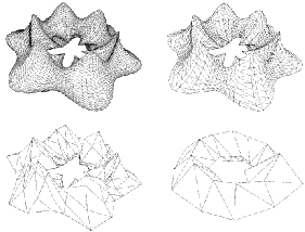
The control parameter for tessellations specifies the maximum deviation from the exact surface. Figure 11-2 illustrates the effects of varying the deviation. The upper left image is appropriate for accurate representation of the surface, the lower right image would be appropriate if the object were in the distant background of a scene.
Details of Figure 11-2
The surface shown in Figure 11-2 was made with the repTest application using an pfFrenetSweptSurface as follows (see “pfFrenetSweptSurface” in Chapter 9):
pfReal profile( pfReal t ) { return 0.5*cos(t*6.0) + 1.25; };
pfSuperQuadCurve3d *cross =
        new pfSuperQuadCurve3d( 0.75, new pfRVec3(0.0, 0.0, 0.0), 3.0 );
pfCircle3d *path = new pfCircle3d( 1.75, new pfRVec3(0.0, 0.0, 0.0) );
pfFrenetSweptSurface *fswept =
                      new pfFrenetSweptSurface( cross, path, profile );
fswept->setHandednessHint( true );
|
The number of triangles in Figure 11-2 decreases as the maximum-deviation parameter chordalDevTol varies from .001 to .01 to .1 to .5 (see “Tessellating Parametric Surfaces”). These numbers should be compared to the scale of the object, which has a maximum diameter of 6.125 = 2(1.75 + 1.75 × .75), a minimum diameter of .875 = 2(1.75 - 1.75 × .75), a maximum height of 2.625 = 2(1.75 × .75), and a minimum height of 1.125 = 2(.75 × .75).
You can apply a tessellator either to a scene graph or to just one node. The tessellators produce a pfGeoSet from an pfRep and place that pfGeoSet in the pfGeode that holds the pfRep.
A tessellation begins with a discrete set of vertices at surface edges. To prevent cracks from appearing between adjacent surfaces, the same set of vertices should be used to tessellate both surfaces.
To address the crack problem, you have several options, which are discussed in “Building Topology: Computing and Using Connectivity Information” in Chapter 10. Table 10-1 lists the different approaches to topology building, and the methods to use for each.
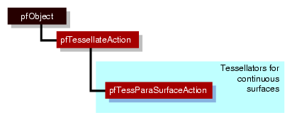
The pfTessellateAction class itself primarily stores statistics concerning the current tessellation. The pfTessParaSurfaceAction class performs the tessellation of surfaces. You can invoke the tessellation on a single surface by calling the following method:
pfTessParaSurfaceAction::tessellator(pfNode *n) |
You can invoke the tessalltion on the entire scene graph by using the following function:
pfdTessellateGeometry(pfNode *root,pfTessParaSurfaceAction *tessAction) |
Nodes which do not derive from pfParaSurface will be left untouched by the pfdTessellateGeometry() function call.
A tessellator will not tessellate a pfRep if the geoset count ( pfGeode::getNumGSets()) is not zero. If you want to retessellate a pfParaSurface, you must call pfParaSurface::clearTessellation(). Note that you can also load a file and force retessellation to occur by using the libpfctol pseudo loader and specifying the + symbol in front of the ctol value you wish to use during tessellation, as shown in the following:
perfly surfaces.pfb.+0.01.ctol |
The class has the following main methods:
class pfTessellateAction : public pfObject
{
public:
// Creating and destroying
pfTessellateAction( void );
virtual ~pfTessellateAction( void );

// Accessor functions
void setExtSize( int s );
int getExtSize( );
int getTriangleCount() const;
int getTriStripCount() const;
int getTriFanCount() const;

void setReverseTrimLoop(const pfBool enable );
pfBool getReverseTrimLoop() const;

void setBuildTopoWhileTess(pfBool _buildTopoWhileTess);
pfBool getBuildTopoWhileTess() const;

void    setTopo(pfTopo * _topo);
pfTopo *getTopo( void )const;

};
|
| getTriangleCount() | Returns the number of all triangles generated by this instance of the tessellator. | |
| getTriStripCount() and getTriFanCount() | Return the number of tristrips or trifans in the tessellation. | |
| setBuildTopoWhileTess() and getBuildTopoWhileTess() | Sets a flag whether surface connectivity is computed during the tessellation traversal. Set the topology data structure to use with setTopo(). If TRUE, before tessellating each surface, the connectivity of all previously tessellated surfaces is used to avoid cracks when tessellating. Notice that the final tessellations of the surfaces in the scene graph may still have cracks because of unforeseen junctions between surfaces. If FALSE, no topology is constructed while tessellating. This leads to two very different possible results:
| |
| setReverseTrimLoop() and getReverseTrimLoop() | Set and recover the orientation of trim loops. Recall that the side of the surface to the left of the trim loop is rendered (see the section “Parametric Surfaces” in Chapter 9). | |
| setTopo() and getTopo() | Set and get the pfTopo that holds the topology information used by the tessellator (see “Summary of Scene Graph Topology: pfTopo” in Chapter 10). |
This section discusses the two classes OpenGL Performer provides for tessellating parametric surfaces. The class pfTessParaSurfaceAction has methods for any parametric surface.
The pfTessParaSurfaceAction class develops tessellations of any pfParaSurface. If a surface has boundary curves, the tessellator starts there and specifies vertices at the edges of the surface. The tessellator then covers the surface with pfGeoSets using the boundary vertices to “pin” the edges of the tessellation. If necessary, the tessellator creates edge vertices by constructing a discrete version of the boundary curve associated with each of the surface's pfEdges. An advantage of starting all tessellations at boundaries is easy coordination of tessellations by several processors.
As part of the tessellation process, you can generate the UV coordinates for each vertex created by the tessellator.
To control the accuracy of a tessellation, you specify a chordal deviation parameter which constrains the distance of edges in the tessellation from the original surface.
The class has the following main methods:
class pfTessParaSurfaceAction : public pfTessellateAction
{
public:
pfTessParaSurfaceAction();
pfTessParaSurfaceAction( pfReal chordalDevTol,
                         pfBool scaleTolByCurvature, int samples);
virtual ~pfTessParaSurfaceAction();

// Accessor functions
void   setChordalDevTol( const pfReal chordalDevTol );
pfReal getChordalDevTol( ) const;

void   setScaleTolByCurvature( const pfReal scaleTolByCurvature )
pfBool   getScaleTolByCurvature() const;

void setSampling( const int samples );
int  getSampling( );

void setNonUniformSampling(const pfBool samples);
pfBool getNonUniformSampling() const;

void setGenUVCoordinates( const pfBool genUVCoordinates );
pfBool getGenUVCoordinates( ) const;

void setGenGeoArrays(pfBool enable);
pfBool getGenGeoArrays() const;

void tessellator(pfParaSurface *sur);
};
|
| pfTessParaSurface() | Creates the class and provides a hint for the maximum deviation of the tessellation from the original surface, indicates whether the tolerance should be scaled by curvature, and provides a hint for how many vertices to include in the tessellation. | |
| setChordalDevTol() and getChordalDevTol() | Set and get the maximum distance from the original surface to the edges produced by the tessellation. | |
| setGenUVCoordinates() and getGenUVCoordinates() | Set and get a flag that indicates whether to generate UV coordinates for the vertices produced in the tessellation. The coordinates for each vertex are stored as the vertex's texture coordinates. | |
| setSampling() and getSampling() | Set and get the hint for the number of triangle vertices in the tessellation along each boundary of the surface. If the surface has no trim curves defining its “outer” edges, then the sampling is along the edges of the UV rectangle that parameterizes the surface. | |
| setScaleTolByCurvature() and getScaleTolByCurvature() | Set and get a flag to control whether the chordal deviation parameter should be scaled by curvature. If nonzero, the tessellation of highly curved areas improves. | |
| setGenGeoArrays() and getGenGeoArrays() | Set and get a flag that determines whether or not the tessellator should generate pfGeoArrays instead of pfGeoSets. By default, this is set to true. | |
| tessellator() | Tessellates an individual surface. |
Although pfTessParaSurface::tessellator() may be used to tessellate an individual surface, it is more common to tessellate a set of surfaces using the pfdTessellateGeometry() function.
The sample code in this section demonstrates how to create higher-level reps such as pfParaSurfaces and pfCurve2ds and to save the output to a file. The lines of code perform the following procedures:
Initializing OpenGL Performer
Creating and tessellating a pfSphereSurface
Saving the scene graph to a .pfb file
The code that follows can be found in the file /usr/share/Performer/src/pguide/libpf/C++/repTest.C on IRIX and Linux and %PFROOT%\Src\pguide\libpf\C++\repTest.cxx on Microsoft Windows.
From main() |
|
|
Initialize OpenGL Performer and prepare for the creation of higher-level reps. |
| pfInit(); pfdInitConverter(argv[1]?argv[1]:”pfb”); shared = (SharedData *)pfCalloc(1, sizeof(SharedData), pfGetSharedArena()); shared->count = 10; pfConfig(); pfGroup *root = new pfGroup();
|
Create Geometry |
|
|
Create the geometry by calling makeObjects(), which in turn calls setupShape() to position the reps and specify their geostate.
|
| makeObjects(root); |
Define setUpShape() |
|
|
The function setupShape() creates a new pfGeode, applies a pfGeoState, and positions the pfRep using pfRep::setOrigin().
|
| static void { // Get the current origin of the object pfRVec3 org; rep->getOrigin(org); // Add the incoming offset to it org[0] += x; org[1] += y; org[2] += z;
// Now reset the origin to include the // incoming offset rep->setOrigin(org);
// Set the appearance of this shape to // be a random color pfGeoState *gState
// Set the geostate for the surface to // be used during tessellation rep->setGState(gState);
// Attach the rep to the scene graph p->addChild(rep); }
|
Define makeObjects() |
|
|
The function makeObjects() sets up the scene graph, defines the grid of reps, and places the surfaces in the scene graph by calling setupShape(). The code here shows the initial lines of makeObjects() (omitting code that controls the grid definition) and the example of defining a trimmed and untrimmed pfSphereSurface.
|
| pfGroup *makeObjects(pfGroup *root) { ....
pfSphereSurface *sphere = new
if(nVersions <= 0) { pfCircle2d *trimCircle2d = new pfCircle2d(1.0, pfRVec2(M_PI/2.0, M_PI));
sphere->addTrimCurve(0, trimCircle2d, }
setupShape(sphere, PF_XDIST*numObject++,
.... }
|

