OpenGL Performer also supports a large set of higher-order primitives that you can include in a scene graph. These higher-order primitives extend the simpler geometric primitives that can be specified using pfGeodes. “Higher-order” means objects other than sets of triangles, and typically implies an object that is defined mathematically.
Designs produced by CAD systems are defined by mathematically defined surface representations. By providing direct support for them, OpenGL Performer expands possible applications from simple walkthrough ability to direct interaction with the design data base.
OpenGL Performer also provides classes to define discrete curves and discrete surfaces.
The objects are discussed in the following sections:
Higher-order geometric primitives, called representations or simply reps, facilitate the design process by providing a library of useful curves and surfaces that ease interactive flexibility, accelerate scene-graph transformations, and reduce the memory footprint of the scene graph. Reps yield these advantages by using parameters to describe objects. Instead of a collection of vertices, which must be manipulated independently to change a surface, reps define surfaces in terms of a relatively small set of control parameters; they are more like pure mathematical objects.
OpenGL Performer allows you to interact with an abstract object (a representation or rep) and treat rendering as a separate operation. A simple example of a rep is a sphere, defined by a radius and a center. After defining a sphere, you can implement how it is rendered in several ways: by tessellating, by a sphere-specific draw routine, or conceivably by hardware. Member functions of geometric-primitive classes allow you to implement the most appropriate way of rendering. The fundamental rendering step of tessellating a representation is discussed in Chapter 11, “Rendering Higher-Order Primitives: Tessellators”.
NURBS curves and surfaces are included in the set of OpenGL Performer reps. OpenGL also has these, but OpenGL Performer NURBS have two advantages:
You can maintain topology, so cracks do not appear at the boundaries of adjacent tessellations when they are drawn.
You have better control over tessellation.
See Chapter 10, “Creating and Maintaining Surface Topology”.
To use reps effectively, you have to understand the OpenGL Performer representations of geometric points and the transformation matrices that are used by the methods of the rep classes.
The classes pfRVec2, pfRVec3, and pfRVec4 define two-, three-, and four-dimensional vectors, and include common operations of vector algebra such as addition, scalar multiplication, cross products, and so on. See the header file Performer/pr/pfLinMath.h for a list of operations defined for each vector.
The classes pfRVec2, pfRVec3, pfRVec4 and pfRMatrix are composed of either single- or double-precision values based on the PF_REAL_IS_DOUBLE #define. Currently, PF_REAL_IS_DOUBLE is set to 0. Hence, all pfRVecs as well as pfRMatrix and the pfReal type are defined as single-precision elements. It is important to use these new types (which are essentially #define statemtents) so that you may change to double- or arbitrary-precision versions of these elements when this functionality is enabled in OpenGL Performer.
One more type, pfBool, has also been added to the repertoire of types for OpenGL Performer and it always maps to the value of a 32-bit integer, regardless of the value of the PF_REAL_IS_DOUBLE #define, which can be found in Performer/pf.h.
In addition, pfLoop has been defined as a 32-bit integer and can take on one of the following values:
PFLOOP_OPEN
PFLOOP_CLOSED
PFLOOP_PERIODIC
PFLOOP_UNRESOLVED
The pfScalar class is the base class for defining scalar functions; it allows you to conveniently read and write functions. The class provides a virtual evaluation method.
The class has the following main methods:
class pfScalar : public pfObject
{ public:
// Creating and destroying
pfScalar();
virtual ~pfScalar();
virtual pfReal eval(pfReal u) = 0;
};
|
The class pfCompositeScalar allows you to define the functional composition of two pfScalars.
The class has the following main methods:
class pfCompositeScalar : public pfScalar
{ public:
// Creating and destroying
pfCompositeScalar( );
pfCompositeScalar(pfScalar *outFun, pfScalar *inFun);
virtual ~pfCompositeScalar();

// Accessor functions
pfScalar *getOutF()
pfScalar *getInF()
void      setOutF(pfScalar *outF);
void      setInF (pfScalar *inF);

pfReal eval(pfReal t);
|
OpenGL Performer provides classes for two trigonometric functions, pfCosScalar and pfSinScalar. The class declarations are similar to that of pfScalar.
The class has the following main methods:
class pfPolyScalar : public pfScalar
{
public:
    // Creating and destroying
pfPolyScalar( void );
pfPolyScalar( int degree, pfReal* coef);
virtual ~pfPolyScalar();
    // Accessor functions
void set( int degree, pfReal* coef);
int getDegree()
pfReal getCoef( int i)
    // Evaluators
pfReal eval(pfReal u);
};
|
Each geometric primitive is defined with respect to its own coordinate system. The elementary definition of an object gives a particular orientation and location with respect to the origin. This reference frame can, in turn, be manipulated by a pfDCS to place it in a scene or manipulate it.
The base class for higher-order primitives has methods that allow you to locate and orient a primitive with respect to its own reference frame. These methods make insertion of pfDCS nodes whenever you want to define the location or orientation of an object or to change the shape of an object unnecessary.
The location is defined by an pfRVec2 or pfRVec3, and the orientation is controlled by a 3 x 3 matrix, held in the class pfRMatrix. If the matrix is not a rotation matrix, you can change the shape of an object, for example, you can distort a sphere into an ellipsoid.
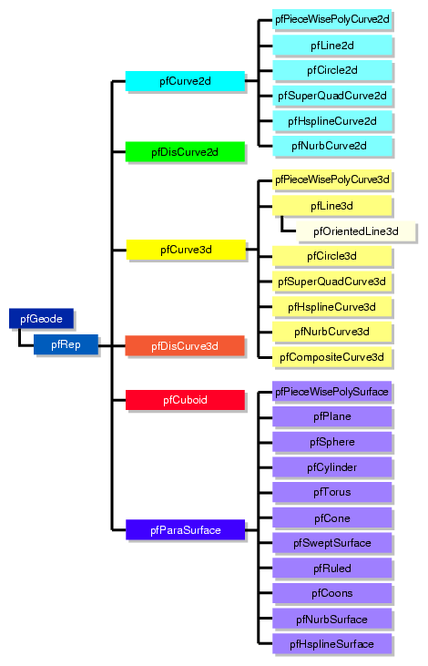
pfRep is the base class for higher-order geometric primitives that are stored in an OpenGL Performer scene graph. A pfRep is derived from a pfGeode and is therefore always a leaf node. Figure 9-1 shows the hierarchy of classes derived from pfRep.
The following sections discuss the subclasses of pfRep:
To experiment with pfReps, you can use and modify the application repTest in /usr/share/Performer/src/pguide/libpf/C++/repTest.C on IRIX and Linux and in %PFROOT%\Src\pguide\libpf\C++\repTest.cxx on Microsoft Windows. This code provides sample instances of several geometric representations, as well as the tessellation and OpenGL Performer calls that render the objects. Sample code from repTest is included with discussions of several of the classes derived from pfRep.
pfRep has methods to orient the object in space, so you do not have to place a pfDCS node above each pfRep to move it from its default position.
The class has the following main methods:
class pfRep : public pfGeode
{
public:
pfRep( );
virtual ~pfRep( );

// Accessor functions
void setOrigin( const pfRVec3&  org );
void setOrient( const pfRMatrix& mat );

void getOrigin(pfRMatrix& mat );
void getOrient(pfRVec3& org );
};
|
| setOrient() | Sets the orientation of the representation with respect to the origin using matrix multiplication. | |
| setOrigin() | Sets the location of the representation with respect to the origin. For example, supplying the vector (1,0,0) shifts the location of the object 1 unit in the direction of the positive X axis. |
pfRep's subclasses typically include evaluator methods to determine coordinates of points, tangents, and normals. If you do not want the values corresponding to the default position, do not call these methods before you use setOrient() and setOrigin() to locate an pfRep. Thus, for example, when defining points on a circle, first set the center and the radius, then call setOrient() to set the orientation, and then evaluate points.
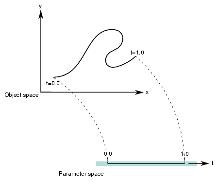
A parametric curve in the plane can be thought of as the result of taking a piece of the real number line, twisting it, stretching it, maybe gluing the ends together, and laying it down on the plane. The base class for parametric curves that lie in the XY plane is the class pfCurve2d.
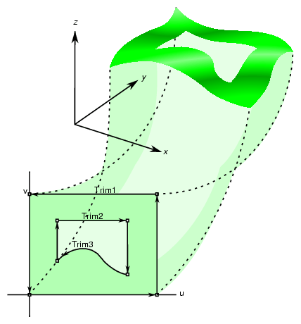
An important use of pfCurve2d is to specify trim curves, which define boundaries for surfaces. Surfaces are parameterized by part of a plane, which in OpenGL Performer is referred to as the uv plane. When an pfCurve2d is used to define a trim curve, it is treated as a curve in the UV plane. This topic is discussed further in the section “Parametric Surfaces”.
Another important use of pfCurve2d is for specifying cross sections for swept surfaces. See “Swept Surfaces”.
OpenGL Performer also provides a class to create discrete curves, pfDisCurve2d.
The following sections discuss planar curve classes, most of which are derived from pfCurve2d:
Planar curves consist of sets of points, described by two-dimensional vectors, pfRVec2s. They are parameterized by the pfReal variable t; as t varies, a point “moves” along the curve. t can be thought of as the amount of time that has passed as a point moves along the curve. Or, t can measure the distance traveled.
More precisely, each component of a point on the curve is a function of t, which lies in the parameter interval (t0, t1) on the real line. Points on the curve are described by a pair of functions of t: (x(t), y(t)).
Classes derived from pfCurve2d inherit a set of evaluator functions which, for a given value of t, evaluate a point on the curve, the tangent and normal vectors at the point, and the curvature. Naturally, the base-class evaluator that locates points on the curve is a pure virtual function.
To evaluate tangent and normal vectors at a point, pfCurve2d provides virtual functions that, by default, use finite-central-difference calculations. To compute the tangent to the curve at p[t], a point on the curve, the tangent evaluator function takes the vector connecting two “nearby” points on the curve, p[t+Dt] - p[t-Dt] where Δτ is “small,” and divides by 2Δτ. Similarly, a finite-central-difference calculation of the normal vector uses the difference between two nearby tangent vectors: n[t] = (t[t+Dt] -t[t-Dt])/2Δτ.
The class has the following main methods:
class pfCurve2d : public pfRep
{
public:
// Creating and destroying
pfCurve2d( );
pfCurve2d( pfReal beginT, pfReal endT  );

virtual ~pfCurve2d();

// Accessor functions
void setBeginT( const pfReal beginT );
void setEndT( const pfReal endT );

pfReal getBeginT();
pfReal getEndT();

pfRVec2 getBeginPt();
pfRVec2 getEndPt();

pfRVec2 getBeginTan();
pfRVec2 getEndTan();

void setClosed( const pfLoop loopVal );
pfLoop getClosed();

void  setClosedTol( const pfReal tol );
pfReal getClosedTol() const;

// Evaluators
virtual void evalPt(    pfReal t, pfRVec2 &pnt ) = 0;
virtual void evalTan(   pfReal t, pfRVec2 &tan );
virtual void evalNorm(  pfReal t, pfRVec2 &norm );
virtual void evalCurv(  pfReal t, pfReal *curv );
virtual void eval(      pfReal t, pfRVec2 &pnt,
                                  pfRVec2 &tan,
                                  pfReal *curv,
                                  pfRVec2 &norm );
};
|
| pfCurve2d(beginT, endT) | Creates an instance of pfCurve2d(). If you do not specify any arguments, then the parametric range of the curve is [0.0,1.0]. | |
| eval() | For a given t, returns the position, tangent, curvature, and normal vectors. | |
| evalPt() | Is a pure virtual function to evaluate position on the curve. | |
| evalTan(), evalCurv(), and evalNorm() | Evaluate the curve's tangent, curvature, and normal vectors, respectively. The default methods approximate the computation using central differences taken about a small Δτ, given by (endT - beginT) * functionTol. functionTol is a static data element specified in the file pfRep.h. | |
| setBeginT() and setEndT(), getBeginPt() and getEndPt() | Set and get the parameter range for the curve. Whenever you set one of these values, the endpoint of the curve changes. Therefore, each of these methods also recomputes the endpoint, which is cached because it is frequently used. Also, the methods recompute the Δτ used to approximate derivatives. Note that all planar curve classes derived from pfCurve2d reuse setBeginT() and setEndT() to define the extents of their curves. | |
| setClosed() and getClosed() | Set and get whether a curve is closed. A closed curve is one for which the endpoints match. OpenGL Performer determines automatically whether curves are closed, but you can override this with setClosed(). | |
| setClosedTol() and getClosedTol() | Set and get the mismatch between endpoints that is allowed when calculating whether curves are closed. |
To specify the origin used to locate an pfCurve2d, use the first two components set by the inherited method pfRep::setOrigin().
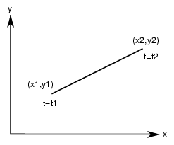
Parametric lines in the plane are defined by beginning and ending points. The parameterization is such that as t varies from t1 to t2, a point on the line “moves,” at a uniform rate, from the beginning to the ending point.
The class has the following main methods:
class pfLine2d : public pfCurve2d
{
public:
// Creating and destroying
pfLine2d();
pfLine2d( pfReal x1, pfReal y1, pfReal t1,
          pfReal x2, pfReal y2, pfReal t2 );
virtual ~pfLine2d();

// Accessor functions
void setPoint1( pfReal x1, pfReal y1, pfReal t1 ) ;
void setPoint2( pfReal x2, pfReal y2, pfReal t2 ) ;
void getPoint1( pfReal *x1, pfReal *y1, pfReal *t1 ) const;
void getPoint2( pfReal *x2, pfReal *y2, pfReal *t2 ) const;
// Evaluators
void evalPt(   pfReal t, pfRVec2 &pnt );
};
|
| pfLine2d() | Creates a parametric line with end points (0,0) and (1,0), and parameter interval (0,1). | |
| pfLine2d(x1, y1, t1, x2, y2, t2) | Creates a parametric line starting at the point (x1, y1) and ending at (x2,y2). The line is parameterized so that t = t1 corresponds to (x1, y1) and t = t2 corresponds to (x2,y2). | |
| evalPt() | Is the only evaluator function defined for this object. The tangent vector is (x2-x1, y2-y1) and the curvature is zero. | |
| setPoint*() and getPoint*() | Set and get the end points of the line. |
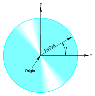
Use the class pfCircle2d to define a parametric circle in the plane. The parameterization is such that t is the angular displacement, in radians, in a counterclockwise direction from the X axis. Figure 9-4 illustrates the parameterization of the circle.
The class has the following main methods:
class pfCircle2d : public pfCurve2d
{
public:
    // Creating amd destroying
pfCircle2d();
pfCircle2d( pfReal rad, pfRVec2 *org );
virtual ~pfCircle2d();
    // Accessor functions
void   setRadius( pfReal rad ) ;
pfReal getRadius() const;
    // Evaluator
void evalPt(   pfReal t, pfRVec2 &pnt );
void evalTan(  pfReal t, pfRVec2 &tan );
void evalCurv( pfReal t, pfReal *curv );
void evalNorm( pfReal t, pfRVec2 &norm );
void eval(     pfReal t,
               pfRVec2 &pnt,
               pfRVec2 &tan,
               pfReal *curv,
               pfRVec2& norm );
};
|
pfCircle2d inherits methods to set the range of parameter values from pfCurve2d.
| pfCircle2d(rad, org) | Creates an instance of a two-dimensional circle with radius rad centered at org. The default circle has unit radius and origin (0,0). To change the default position, use the methods setOrigin() and setOrient() inherited from pfRep. | |
| setRadius() and getRadius() | Set and get the circle's radius. |
pfCircle2d provides exact calculations for the evaluator functions inherited from pfCurve2d.
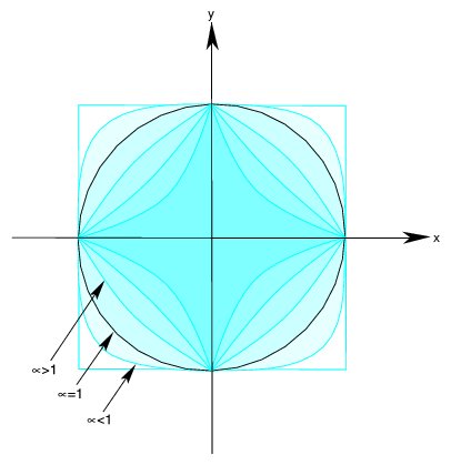
The class pfSuperQuadCurve2d provides methods to define a generalization of a circle that, when used for constructing a swept surface, is convenient for generating rounded, nearly square surfaces, or surfaces with sharp cusps (see “Swept Surfaces”). Two examples of superquadrics appear in repTest.
The position along the curve is specified by an angle from the x axis, in the same as for an pfCircle2d. The shape of the curve is controlled by a second parameter.
A superquadric is the set of points (x,y) given by the following equation that clearly expresses the relationship to the equation of a circle:
The above equation can be written in a parametric form:
The family of curves generated by these equations as the quantity α varies can be described as follows (see Figure 9-5).
Four points are always on the curve for any value of a: (\ξβ1 ρ, 0) and (0, \ξβ1 ρ).
If α is 1, the curve is a circle of radius r.
As α approaches zero, the circle expands to fill a square of side 2r as if you were inflating a balloon in a box.
As α approaches infinity, the circle contracts towards the two diameters along the x and y axes, approaching two orthogonal lines as if you deflated a balloon with two rigid orthogonal sticks inside it.
The class has the following main methods:
class pfSuperQuadCurve2d : public pfCurve2d
{
public:
// Creating and destroying
pfSuperQuadCurve2d();
pfSuperQuadCurve2d( pfReal radius,
                    pfRVec2 *origin,
                    pfReal exponent );
virtual ~pfSuperQuadCurve2d();

// Accessor functions
void   setRadius( pfReal _radius );
pfReal getRadius() const;

void   setExponent( pfReal _exponent );
pfReal getExponent() const;

// Evaluator
void evalPt(   pfReal t, pfRVec2 &pnt );
};
|
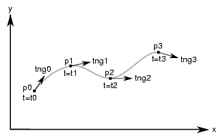
A spline is a mathematical technique for generating a single geometric object from pieces. An advantage of breaking a curve into pieces is greater flexibility when you have many points controlling the shape: changes to one piece of the curve do not have significant effects on remote pieces. To define a spline curve for a range of values for the parameter t, say from 0 to 3, you “tie” together pieces of curves defined over intervals of values for t. For example, you might assign curve pieces to the three intervals 0 to 1, 1 to 2, and 2 to 3. The four points in the set of parameters, 0, 1, 2, and 3, define the endpoints of the intervals and are called knots.
A Hermite-spline curve is a curve whose segments are cubic polynomials of the parameter t, where the coefficients of the polynomials are determined by the position and tangent to the curve at each knot point. Thus the curve passes through each of a set of specified points with a specified tangent vector. The set of knot points must be increasing values of the parameter t.
The class for creating Hermite spline curves is pfHsplineCurve2d. The class has the following main methods:
class pfHsplineCurve2d : public pfCurve2d
{
public:
// Creating and destroying
pfHsplineCurve2d();
virtual ~pfHsplineCurve2d();

// Accessor functions
void setPoint(   int i, const pfRVec2 &p );
void setTangent( int i, const pfRVec2 &tng );
void setKnot(    int i, pfReal t );

int getKnotCount() const;
pfRVec2* getPoint( int i );
pfRVec2* getTangent( int i );
pfReal  getKnot( int i );

// Evaluator
virtual void evalPt( pfReal t, pfRVec2 &pnt );
};
|
The acronym NURBS stands for “nonuniform rational B-splines.” NURBS define a set of curves and surfaces that generalizes Bezier curves. Both NURBS curves and Bezier curves are “smooth” curves that are well suited for CAD design work. They are essentially determined by a set of points that controls the shape of the curves, although the points do not lie on the curves.
Because NURBS properties are not widely known, a discussion of their features precedes details of how to create instances of them. The discussion is necessarily brief and is intended to provide the minimum amount of information needed to start using OpenGL Performer NURBS classes.
This general discussion of NURBS is presented in the following sections:
The OpenGL Performer classes allow you to treat a NURBS object as a black box that takes a set of control parameters and generates a geometric shape. A NURBS object's essential properties are rather straightforward, although the underlying mathematics are complex. Unlike lines and circles, NURBS can represent a large set of distinct complex shapes. Because of this flexibility, developing a NURBS object is often best done interactively. For example, you could allow a user to design a curve using an interface in which control parameters are changed by clicking and dragging and by using sliders.
There are three classes:
The pfNurbCurve2d class generates curves in the plane, the simplest NURBS object provided by OpenGL Performer.
The pfNurbCurve3d class generates NURBS curves in three-dimensional space.
The pfNurbSurface class generates NURBS surfaces, which extend the ideas underlying NURBS curves to two-dimensional objects. The principles for controlling the shapes of these objects are all essentially the same.
This section provides some theoretical background information on NURBS elements. If you already understand NURBS, continue with “NURBS Curves in the Plane”)
NURBS are defined by the following elements, discussed in this chapter:
Nonuniform knot points (see “Knot Points”)
A control hull consisting of control points (see “Control Hull”)
Weighting parameters for control points (see “Weights for Control Points”)
The knot points determine how and where the pieces of the NURBS object are joined. The knots are nondecreasing— but not necessarily uniformly spaced or distinct—values of the parameter t for the curve. The sequence of knots need not have uniform spacing in the parameter interval. In fact, the mathematics of NURBS make it possible and, perhaps, necessary to repeat knot values; that is, knots can appear with a certain multiplicity. The number of knot points is determined by counting all the knot points, including all multiplicities.
For example, although the sequence (0,0,0,0,1,1,1,1) has only two distinct knot points, the number of knot points is eight. (This example it is the set of knot points for a cubic Bezier curve defined on the interval 0 to 1). How to determine the order of a NURBS curve is discussed in “Features of NURBS and Bezier Curves”.
The control hull is the set of all points that determine the basic shape of NURBS object. The effect of the control hull is determined by a “B-spline.”
A B-spline is a basis spline; a set of special curves associated with a given knot sequence from which you can generate all other spline curves having the same knot sequence and control hull. For each interval described by the knot sequence, the corresponding piece of a B-spline curve is a Bezier curve.
B-spline curves are like Bezier curves in that they are defined by an algorithm that acts on a sequence of control points, the control hull, which lie in the plane or in three-dimensional space.
The third set of control parameters for a NURBS curve is the set of weights associated with the control points.
A rational B-spline consists of curves that have a weight associated with each control point. The individual pieces of a NURBS curve usually are not Bezier curves but rational Bezier curves. The values of the weights have no absolute meaning; they control how “hard” an individual control point pulls on the curve relative to other control points. If the weights for all the control points of a rational Bezier curve are equal, then the curve becomes a simple Bezier curve. Weights allow construction of exact conic sections, which cannot be made with simple Bezier curves.
Bezier curves have the following properties:
They are “nice” polynomial curves whose degree is one less than the number of control points.
For a polynomial curve, each of the components is a polynomial function of the parameter t. The number of coefficients in the polynomial, the order of the polynomial, is equal to the number of control points.
The control points determine the shape of the Bezier curve, but they do not lie on the curve, except the first and last control points.
NURBS curves differ in the following ways:
The order of the polynomial pieces that make up the NURBS curve depends on the number of control points and the number of knot points. The order of a NURBS curve is the difference between the number of knots, accounting for multiplicity, and the number of control points. That is,
order = number of knot points - number of control points
The relationship between the curves and the control points is looser than for a Bezier curve. It also depends on the knot sequence and the sequence of weights.
If you have a surface developed from the alternative expression for a NURBS surface:
 |
you must change the coordinates of the control points to get the same surface from OpenGL Performer; you convert the coordinates of the control points from (x,y,w) to (wx,wy,w).
The class pfNurbCurve2d defines a nonuniform rational B-spline curve in the plane, the simplest NURBS object provided by OpenGL Performer.
The class has the following main methods:
class pfNurbCurve2d : public pfCurve2d
{
public:
// Creating and destroying
pfNurbCurve2d( );
pfNurbCurve2d( pfReal tBegin, pfReal tEnd );
virtual ~pfNurbCurve2d( );

// Accessor functions
void setControlHull(     int i, const pfRVec2 &p );
void setControlHull(     int i, const pfRVec3 &p );
void setWeight(          int i, pfReal w  );
void setKnot(            int i, pfReal t  );
void setControlHullSize( int s            );

pfRVec2* getControlHull( int i );
pfReal  getWeight( int i );
int     getControlHullSize( );
int     getKnotCount( );
pfReal  getKnot( int i );
int     getOrder( );

void removeControlHullPnt(int i);
void removeKnot(int i);

// Evaluator
virtual void evalPt( pfReal t, pfRVec2 &pnt );
};
|
| pfNurbCurve2d(tBegin, tEnd) | Creates a NURBS curve in the plane with the specified parameter domain. The default parameter domain is 0.0 to 1.0. | |
| evalPt() | Is a pure virtual function inherited from pfCurve2d, and produces unpredictable results until you set the control parameters. | |
| setControlHull(i, p) and getControlHull(i) | Set and get the two-dimensional control point with index i to the value p. If you supply pfRVec3 arguments, the location of the control points is set by the first two components; the last component is their weight. | |
| setControlHullSize() | Gives a hint about how big the control hull array is. This is not mandatory but uses time and space most efficiently. | |
| setKnot(i, t) and getKnot(i) | Set and get the knot point with index i and the value t. | |
| setWeight(i, w) and getWeight(i) | Set and get the weight of the control point with index i and weight w. |
A piecewise polynomial curve consists of an array of polynomial curves. Each polynomial curve is a polynomial mapping from t to UV plane, where the domain is a subinterval of [0,1]. The polynomial coefficients are set by setControlHull().
Notice that an pfPieceWisePolyCurve2d is a subclass of pfCurve2d. The domain of a pfPieceWisePolyCurve2d is defined to be [0, n] where n is the number of pieces.
If reverse is 0, then for any given t in [0, n], its corresponding uv is evaluated in the following way: The index of the piece that corresponds to t is floor(t), and the polynomial of that piece is evaluated at w1 + (t-floor(t)) * (w2-w1) to get the (u,v), where [w1, w2] is the domain interval (set by setLimitParas()) of this piece.
If reverse is 1, then for any given t in [0,n], we first transform t into n-t, then perform the normal evaluation (at n-t) as described in the preceding paragraph.
The class has the following main methods:
class pfPieceWisePolyCurve2d : public pfCurve3d
{
public:
// Creating and destroying
pfPieceWisePolyCurve2d ( );
virtual ~pfPieceWisePolyCurve2d ( );

//Accessor functions
void setControlHull ( int piece, int i, const pfRVec2& p);
pfRVec2& getControlHull ( int piece, int i);
void setLimitParas ( int piece, pfReal w1, pfReal w2);
void setReverse ( int _reverse);
pfRVec2& getLimitParas ( int piece);
int getReverse ( ) const;
int getPatchCount ( ) const;
int getOrder ( int piece);
virtual void evalPt ( pfReal t, pfRVec2& pnt);
virtual void evalBreakPoints ( pfParaSurface* sur);
};
|
setControlHull(piece, i, p) defines the ith polynomial coefficient of the pieceth polynomial curve to p. p[0] is for the u coefficient and p[1] is for the v coefficient. setLimitParas() sets the domain interval.
The class pfPieceWisePolyCurve3d has parallel functionality and declaration.
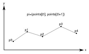
The class pfDisCurve2d is the base class for making a discrete curve from line segments connecting a sequence of points in the plane. Because pfDisCurve2d is not derived from pfCurve2d, it does not inherit that class's finite difference functions for calculating derivatives, therefore, pfDisCurve2d includes member functions that calculate arc length, tangents, principal normals, and curvatures using finite central differences. Figure 9-7 illustrates the definition of the curve by a set of points.
The class has the following main methods:
class pfDisCurve2d : public pfRep
{
public:
// Creating and destroying
pfDisCurve2d( void );
pfDisCurve2d( int nPoints, pfReal *points );

virtual ~pfDisCurve2d( void );

// Accessor functions
void set (int nPoints, pfReal* points);
pfRVec2 getBeginPt() const;
pfRVec2 getEndPt() const;

pfLoop getClosed();
void   setClosed( pfLoop c );

void setPoint( int i, const pfRVec2& pnt );
pfRVec2 getPoint( int i) const;
int getPointCount(); const;
pfRVec2 getTangent(int i) const;
pfRVec2 getNormal(int i) const;
pfReal getCurvature(int i) const;

// Evaluators
void computeTangents( );
void computeNormals( );
void computeCurvatures( );
void computeDerivatives( );
};
|
| pfDisCurve2d(nPoints, points) | Creates a discrete curve from an array of point coordinates. The constructor assumes that the coordinates of the points are stored in pairs sequentially; thus the points array is nPoint*2 in length. | |
| computeCurvatures() | Computes the curvature, which is the magnitude of the normal vector. | |
| computeDerivatives() | Is a convenience function that calls (in order) the tangent, normal, and curvature functions. | |
| computeNormals() | Computes the principal normal at a point using finite central differences and stores the result in the class member pfDvector n. For the point p[i], the normal vector is computed to be the difference vector between the tangents at the two neighboring points, t[i+1] - t[i-1], divided by the sum of the distances from p[i] to the two neighboring points. | |
| computeTangents() | Computes the arc lengths of segments and then uses finite central differences to compute the tangents. For the point p[i], the tangent vector is computed to be the vector between its two neighboring points, p[i+1] - p[i-1], divided by the sum of the distances from p[i] to the two neighboring points. The tangents are stored in the pfDvector t, the arc lengths in the pfDvector ds, and the total arc length in arcLength. | |
| getCurvature() | Returns the value of the curvature at the ith point. | |
| getNormal() | Returns the value of the normal at the ith point. | |
| getPoint() | Returns the value of the ith point. | |
| getPointCount() | Returns the value of the ith point. | |
| getTangent() | Returns the value of the tangent at the ith point. |
The class pfCurve3d is the base for parametric curves that lie in three-dimensional space. Among other uses, a curve in space could locate a moving viewpoint in a CAD walk-through.
The nature of these curves is essentially the same as those of pfCurve2d curves, except pfCurve3d curves are made of points described by pfRVec3s. The components of the points are assumed to be x, y, and z coordinates. Refer to the section “Planar Curves” for a discussion of the basic features of parametric curves.
This section parallels the discussion in “Planar Curves”, and emphasizes the (not very great) differences that distinguish spatial curves:
The class declaration for pfCurve3d is in the file /usr/include/Performer/pf/pfCurve3d.h on IRIX and Linux and %PFROOT%\Include\pf\pfCurve3d.h on Microsoft Windows. Its declaration is essentially identical to the declaration for pfCurve2d. The difference is that all pfRVec2 variables are replaced by pfRVec3 variables.
The base class for lines in space, pfLine3d, is essentially the same as pfLine2d, discussed in “Lines in the Plane”. The main differences are due to the need to manage three-dimensional vectors. Thus all vector variables are pfRVec3 and the constructor takes six variables to define the endpoints of the line.
The default orientation of the curve is identical to that for the planar curve pfLine2d; you can translate and rotate the line in three-dimensional space with the methods setOrigin() and setOrient() inherited from pfRep.
The class pfOrientedLine3d is derived from pfLine3d, and adds vectors to define a moving three-dimensional reference frame for the line. This object is useful if you want a straight-line path for an pfFrenetSweptSurface (see “Swept Surfaces” and, in particular, “Class Declaration for pfFrenetSweptSurface”).
The methods of pfOrientedLine3d add to the description of the line an “up” vector, which you specify. The normal to the line is calculated from the direction of the line and the up vector.
The class pfCircle3d defines a parametric circle with an arbitrary location and orientation in space. The parameterization of the circle, before you change its location or orientation, is such that t is the angular displacement, in radians, in a counterclockwise direction from the x axis.
The class declaration for pfCircle3d is identical to that for pfCircle2d, discussed in “Circles in the Plane”, except for the changes from pfRVec2 to pfRVec3. The member functions perform the same operations. For more information, see the discussion in the section “Circles in the Plane”.
If the matrix you use to orient an pfCircle3d does not correspond to a rotation about an axis—that is, the matrix is not orthonormal— you not only change the tilt of the plane in which the circle lies but also change the radius, and may distort the circle into an ellipse. .
The class pfSuperQuadCurve3d provides methods to define a superquadric in space (see “Superquadric Curves: pfSuperQuadCurve2d”). The class declaration is identical to that for pfSuperQuad2d except that position on the curve is defined by an pfRVec3.
The default orientation of the curve is identical to that for the planar curve pfSuperQuad2d; you can translate and rotate the curve in three-dimensional space with the methods setOrigin() and setOrient() inherited from pfRep.
The class pfHsplineCurve3d provides methods to define a Hermite spline curve in space. The definition of the curve is the same as that for a Hermite spline curve in the plane, discussed in “Hermite-Spline Curves in the Plane”. The class declaration is the same as that for pfHsplineCurve2d, but the position and tangent vectors are pfRVec3s.
The basic properties of NURBS are discussed in the section “NURBS Overview”. In an effort to keep things as simple as possible, the discussion in that section has a bias toward curves in the plane. But the principles and control parameters are, with one difference, the same for NURBS curves in space.
The difference is that control points for NURBS curves in space can be anywhere in space instead of being restricted to a plane. The section “Examples of NURBS Curves” in Chapter 8 of The Inventor Mentor presents illustrations of NURBS curves in space, along with their control parameters.
The class pfNurbCurve3d is the base class for NURBS curves in space. Its class declaration is practically identical to that for pfNurbCurve2d but all occurrences of pfRVec2 are changed to pfRVec3. In addition, the vector argument of setControlHull() can be an pfRVec3, if you just want to specify control point locations, or an pfRVec4, if you want to append weighting information as a fourth component. See the discussion in the section “NURBS Curves in the Plane”.
A planar curve in the u-v plane describes a curve on the surface, given a parameterized surface (see the section “Parametric Surfaces”). Each point on the curve in the parameter plane is “lifted up” to the surface. Such curves are known as composite curves because they are described mathematically as the composition of the function describing the curve and the function describing the surface. The edge of a surface defined by a trim curve is a composite curve.
pfCompositeCurve3d is the base class for composite curves. This class is useful for defining trim curves and surface silhouettes in the parametric surface's coordinate system.
The class has the following main methods:
class pfCompositeCurve3d : public pfCurve3d
{
public:
// Creating and destroying
pfCompositeCurve3d( );
pfCompositeCurve3d( pfParaSurface *sur, pfCurve2d *cur );
virtual ~pfCompositeCurve3d( );

// Accessor functions
void set( pfParaSurface *sur, pfCurve2d *cur );
pfParaSurface* getParaSurface() const;
pfCurve2d* getCurve2d() const;

// Evaluator
void evalPt( pfReal u, pfRVec3 &pnt );
};
|
The class pfDisCurve3d is the base class for making a discrete curve of line segments connecting a sequence of points in space. The class declaration for pfDisCurve3d is identical to that for pfDisCurve2d, discussed in “Discrete Curves in the Plane”, but pfRVec2 changes to pfRVec3. The member functions perform the same operations.
One application of an pfDisCurve3d and pfHsplineCurve3d is to use them to interactively specify routing for tubing. These are the operations to perform:
Create a pfDisCurve3d from a set of points. See “Discrete Curves in Space”.
Use the points and tangents to the discrete curve to create a continuous path with an pfHsplineCurve3d. See “Hermite Spline Curves in Space”
Use the continuous path in an pfFrenetSweptSurface with a circular cross section. See “pfFrenetSweptSurface”.
A parametric surface can be thought of as the result of taking a piece of a plane, twisting and stretching it, maybe gluing edges of the piece together, and placing it in space.
The introductory discussion of parametric surfaces occurs in the following sections:
The subclasses of pfParaSurface are discussed in the subsequent sections:
Instances of most of the pfParaSurface subclasses are used in the sample application /usr/share/Performer/src/pguide/libpf/C++/repTest.C on IRIX and Linux and %PFROOT\Src\pguide\libpf\C++\repTest.cxx on Microsoft Windows.
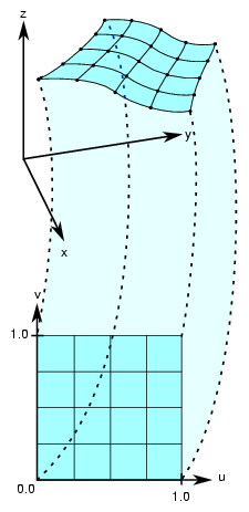
To locate a point on a parametric surface, you need two parameters, referred to as u and v in OpenGL Performer. The set of u and v values that describe the surface are known as the parameter space, or coordinate system, of the surface (see Figure 9-8).
More precisely, the coordinates of the points in space that define a parametric surface are described by a set of three functions of two parameters: (x(u,v), y(u,v), z(u,v)).
Well-known examples of a parametric surface are a sphere or a globe. On a globe you can locate points with two parameters: latitude and longitude. The rectangular grid of latitude and longitudes is the coordinate system that describes points on the globe.
To define the extent of a parametric curve, pick an interval. For accurate trimming of a parametric surface, you need more complex tools. You are likely to need:
Edges for the surface other than those defined by the limits of the coordinate system. For example, to define a pipe elbow, you might join two cylinders by a piece cut from a torus.
Holes in a surface, for example, to define a T-joint intersection of pipes.
OpenGL Performer keeps the trim loop side on the left as you look down on the u-v plane while a point moves along the curve in the direction of increasing t; you can hold on to the surface with your left hand as you go along the trim loop. Thus a clockwise loop removes a hole; a counterclockwise loop keeps the enclosed region and eliminates everything outside. Do not create a trim loop that crosses itself like a figure eight.
OpenGL Performer allows you to maintain curves to define the edges of a surface. These curves are pfCurve2d objects defined in the u-v plane that are “lifted” to the surface by the parameterization. The main use of these curves is to eliminate a portion of the surface on one side of the curve. The name of a curve in the coordinate system that is used to define (possibly a piece of) such a surface edge is a trim curve. One or more joined trim curves form a sequence called a trim loop. To be of use, trim curves should form a closed loop or reach the edges of the coordinate system for the surface. Figure 9-9 illustrates trim loops and their effect on a surface.
An pfEdge defines a trim curve in u, v space. pfEdge holds information about a surface's adjacency. Each pfEdge identifies an pfBoundary, which the class pfTopo uses to keep track of surface connectivity, and continuous and discrete versions of the trim curve associated with the boundary. The members of an pfEdge are set by the toplogy building tools; the methods of pfEdge access the members. Topology building and the classes pfTopo and pfBoundary are discussed further in Chapter 10, “Creating and Maintaining Surface Topology”.
The information held in pfEdge allows tessellators to determine whether a set of vertices has already been developed for points shared with other surfaces. You can also find other surfaces that have the same edge or trim-curve endpoint as that defined by a given trim curve.
The set*() methods are mainly used when reading surface data from a file and creating OpenGL Performer data structures.
The class has the following main methods:
class pfEdge : public pfObject
{
public:
// Creating and destroying
pfEdge();
~pfEdge();

pfCurve2d *getContCurve();
void setContCurve(pfCurve2d *c);

pfDisCurve2d *getDisCurve();
void setDisCurve( pfDisCurve2d *d);

int getBoundary();

void setBoundaryDir( int dir );
int getBoundaryDir();
};
|
pfParaSurface is the base class for parametric surfaces in OpenGL Performer. As for the base classes pfCurve2d and pfCurve3d, pfParaSurface includes a pure virtual function to evaluate points on the surface and default evaluator functions that calculate derivatives using finite central differences. The surface normal at a point is the cross product of the partial derivatives.
For parametric curves whose extent is defined by the interval of values for t, the extent of an pfParaSurface is, initially, defined by all the points in its parameter space.
The class has the following main methods:
class pfParaSurface : public pfRep
{
public:
// Creating and destroying
pfParaSurface( pfReal _beginU = 0, pfReal _endU = 1,
               pfReal _beginV = 0, pfReal _endV = 1,
               int    _topoId = 0, int    _solid_id = -1 );

virtual ~pfParaSurface();

// Accessor functions
void setBeginU( pfReal u );
void setEndU(   pfReal u );
void setBeginV( pfReal v );
void setEndV(   pfReal v );
void setSolidId( int solidId);
void SetTopoId( int topoId);
void setSurfaceId (int surfaceId);
pfReal getBeginU() const;
pfReal getEndU() const;
pfReal getBeginV() const;
pfReal getEndV() const;

int     getTrimLoopCount();
pfLoop  getTrimLoopClosed( int loopNum );
int     getTrimCurveCount( int loopNum );
pfEdge* getTrimCurve( int loopNum, int curveNum );

int     getTopoId();
int     getSolidId();
int     getSurfaceId();

void setHandednessHint( pfbool _clockWise );
pfbool getHandednessHint() const;

pfGeoState* getGState( ) const;
int setGState( pfGeoState *gState );

void insertTrimCurve( int loopNum, pfCurve2d *c, pfDisCurve2d *d );

// Explicit add a trim curve to a trim loop
void addTrimCurve(int loopNum, pfCurve2d *c, pfDisCurve2d *d );
void setTrimLoopClosed(  int loopNum, pfLoop closed );

// Surface evaluators
virtual void evalPt(   pfReal u, pfReal v, pfRVec3 &pnt ) = 0;
virtual void evalDu(   pfReal u, pfReal v, pfRVec3 &Du );
virtual void evalDv(   pfReal u, pfReal v, pfRVec3 &Dv );
virtual void evalDuu(  pfReal u, pfReal v, pfRVec3 &Duu );
virtual void evalDvv(  pfReal u, pfReal v, pfRVec3 &Dvv );
virtual void evalDuv(  pfReal u, pfReal v, pfRVec3 &Duv );
virtual void evalNorm( pfReal u, pfReal v, pfRVec3 &norm );

// Directional derivative evaluators
virtual void evalD( pfReal u, pfReal v, pfReal theta, pfRVec3 &D );
virtual void evalDD( pfReal u, pfReal v, pfReal theta, pfRVec3 &DD );

virtual void eval( pfReal u, pfReal v,
pfRVec3 &p,            // The point
pfRVec3 &Du,           // The derivative in the u direction
pfRVec3 &Dv,           // The derivative in the v direction
pfRVec3 &Duu,          // The 2nd derivative in the u direction
pfRVec3 &Dvv,          // The 2nd derivative in the v direction
pfRVec3 &Duv,          // The cross derivative
pfReal &s,            // Texture coordinates
pfReal &t  );

void clearTessallation();
};
|
| addTrimCurve(j, curve, discurve) | Is a quick function for building a trim loop that assumes you know the order of trim curves. It adds curve to the end of the list of continuous trim curves for the jth trim loop, and adds discurve to the list of discrete trim curves. For example, you could build the trim loops in Figure 9-9 by starting with one segment and successively adding segments. If the beginning of curve does not match the end of the previously added curve, use insertTrimCurve(), which finds the right place for the curve by assuming topological consistency. | |
| eval() | Returns the evaluator functions. The last two arguments of eval() are the same as the input coordinates u and v. | |
| evalDu(), evalDv(), evalDuu(), evalDvv(), and evalDuv() | Are evaluator functions that use central differences to calculate the first and second derivatives, identified by the lowercase u and v in the function names, at a point on the surface. | |
| evalD() and evalDD() | Calculate the first and second directional derivatives in the direction given by an angle theta from the u axis in the parameter space. | |
| evalNorm() | Calculates the unit normal to the surface. | |
| evalPt() | Is a pure virtual function that you define to specify a surface. | |
| pfParaSurface() | Constructs a parametric surface. You can specify the topology and the surface to which the parametric surface belongs. See “Summary of Scene Graph Topology: pfTopo” in Chapter 10. | |
| insertTrimCurve(j, curve, discurve) | Is a slower function than addTrimCurve() for building a trim loop that attempts to guarantee all curves form a sensible trim loop sequence. It compares the ends of curve with the ends of the trim curves that are already in the jth trim loop and inserts curve at the appropriate point in the list. Similarly, addTrimCurve() inserts the discrete curve discurve. If insertTrimCurve() cannot find an endpoint match, it adds curve to the end of the list of trim curves. If you are building a trim loop by inserting trim curves end to end, then addTrimCurve() gives the same result but more quickly. | |
| setBeginU(), setBeginV(), etc. | Set and get the start and end values for the coordinate space of the surface. The coordinate space is a rectangle in the UV plane. The default is the unit square; u and v both lie in the interval (0,1). | |
| getTrimLoopCount() | Returns the number of trim loops for the pfParaSurface. | |
| getTrimLoopClosed() and setTrimLoopClosed() | Get and set the flag indicating whether a given trim loop is closed. OpenGL Performer determines this for you, so use setTrimLoopClosed() with caution; you could get a meaningless result. | |
| getTrimCurveCount() | Returns the number of trim curves in the specified trim loop. | |
| getTrimCurve(i,j) | Returns the pfEdge for the trim curve with index i in the trim loop with index j. | |
| clearTessellation() | Removes all data that resulted from previous tessellation. This removal allows the surface to be retessellated with a different tolerance. For each trim curve, the disCurve is deleted if the contCurve is not NULL. The xyzBoundary in its boundary structure is deleted. Also, the tessellated triangles (csGeometry) are removed. | |
| getGState() and setGState() | Get and set the pfGeoState to be used when tessellating the surface and setting pfGeoStates on generated geometry (pfGeoSets). setGState() returns 1 if successful, –1 otherwise. |
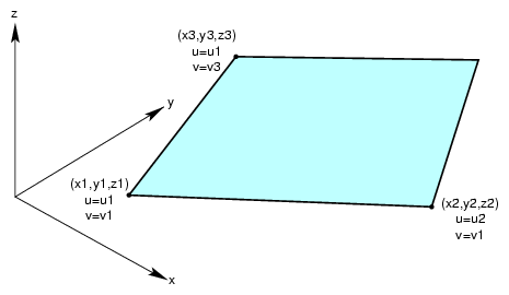
The simplest parametric surface is a plane. The class pfPlaneSurface defines a plane by two parameter intervals and three points that define the two coordinate directions. Figure 9-10 illustrates the parameterization of an pfPlaneSurface.
The class has the following main methods:
class pfPlaneSurface : public pfParaSurface
{
public:
// Creating and destroying
pfPlaneSurface();
pfPlaneSurface( pfReal x1, pfReal y1, pfReal z1, pfReal u1, pfReal v1,
         pfReal x2, pfReal y2, pfReal z2, pfReal u2,
         pfReal x3, pfReal y3, pfReal z3, pfReal v3 );
virtual ~pfPlaneSurface();

// Accessor functions
void setPoint1( pfReal x1, pfReal y1, pfReal z1, pfReal u1, pfReal v1);
void setPoint2( pfReal x2, pfReal y2, pfReal z2, pfReal u2 );
void setPoint3( pfReal x3, pfReal y3, pfReal z3, pfReal v3 );

void getPoint1( pfReal *x1, pfReal *y1, pfReal *z1,
                pfReal *u1, pfReal *v1 );
void getPoint2( pfReal *x2, pfReal *y2, pfReal *z2, pfReal *u2 );
void getPoint3( pfReal *x3, pfReal *y3, pfReal *z3, pfReal *v3 );

// Evaluators
void evalPt( pfReal u, pfReal v, pfRVec3 &pnt );
void evalDu( pfReal u, pfReal v, pfRVec3 &Du );
void evalDv( pfReal u, pfReal v, pfRVec3 &Dv );
void evalNorm( pfReal u, pfReal v, pfRVec3 &norm );
}
|
| pfPlaneSurface() | When you construct the class, you can specify the plane with three points and two parameter intervals or you can use the setPoint*() methods. Those parameters have the following meanings:
| |
| setPoint*() and getPoint*() | Set and get each of the points that define the plane and their corresponding parameter values (see pfPlaneSurface()). |
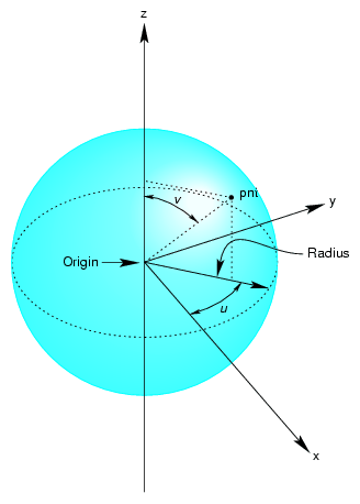
The surface of the sphere is parameterized by angles, in radians, for latitude and longitude; v corresponds to longitude, u to latitude. Figure 9-11 illustrates the parameterization of an pfSphereSurface.
The class has the following main methods:
class pfSphereSurface : public pfParaSurface
{
public:
// Creating and destroying
pfSphereSurface( );
pfSphereSurface( pfReal radius );
virtual ~pfSphereSurface( );

// Accessor functions
void setRadius( pfReal radiusVal );
pfReal getRadius( ) const;

// Evaluators
void evalPt(   pfReal  u, pfReal v, pfRVec3 &pnt );
void evalNorm( pfReal  u, pfReal v, pfRVec3 &norm );
}
|
The constructor defines a sphere centered on the origin with the specified radius. The default radius is 1. The evaluator functions do not use finite-difference calculations for derivatives.
Any point on the sphere is represented as:
x = radius * cos(u) * sin(v) y = radius * sin(u) * sin(v) z = radius * cos(v) |
The following code from the sample application repTest illustrates how an instance of an pfSphereSurface of radius three would be created:
pfSphereSurface *sphere = new pfSphereSurface( 3 );

// under certain conditions, a trim curve is added that keeps only the // portion of the surface above a circle
if ( nVersions <= 0 )
{
pfCircle2d  *trimCircle2d =
                   new pfCircle2d( 1.0, new pfRVec2(M_PI/2.0,M_PI) );
sphere->addTrimCurve( 0, trimCircle2d );
}
setUpShape( sphere, PF_XDIST*numObject++, Y, PF_VIEWDIST );
|
setUpShape() locates the sphere in the scene, tessellates it, and places it in the scene graph (see /usr/share/Performer/src/pguide/libpf/C++/repTest.C on IRIX and Linux and %PFROOT%\Src\pguide\libpf\C++\repTest.cxx on Microsoft Windows). Creating an instance of any pfRep is basically the same, as subsequent examples in the discussions of other pfReps will show.
The pfCylinderSurface class provides methods for describing a cylinder.
A cylinder can be defined geometrically as the surface in space that is swept by moving a circle along an axis that is perpendicular to the plane of the circle and passes through the center of the circle.
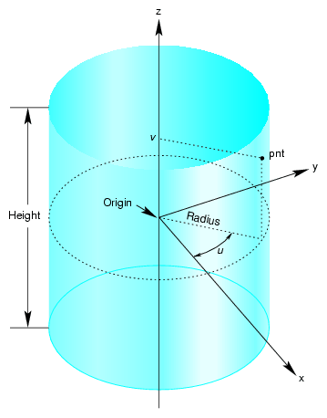
The parameterization of an pfCylinderSurface is as follows: u represents the position on the circle and that v represents the position along the axis.
The class has the following main methods:
class pfCylinderSurface : public pfParaSurface
{
public:
// Creating and destroying
pfCylinderSurface( void );
pfCylinderSurface( pfReal radius, pfReal height );
virtual ~pfCylinderSurface();

// Accessor functions
void setRadius( pfReal radiusVal ) ;
void setHeight( pfReal heightVal );

pfReal getRadius( ) const;
pfReal getHeight( ) const;

// Evaluators
void evalPt(   pfReal  u, pfReal v, pfRVec3 &pnt );
void evalNorm( pfReal  u, pfReal v, pfRVec3 &norm );
};
|
pfCylinderSurface( radius, height ) constructs a cylinder with the specified height and radius. By default, the z axis is the cylinder's axis and the cylinder is centered on the origin, extending in the positive and negative z directions for one-half the height.
For the default orientation, u measures the angle from the x-z plane in a counterclockwise direction as you look down on the x-y plane and v measures the distance along the z-axis. The default radius is 1 and the default height is 2.
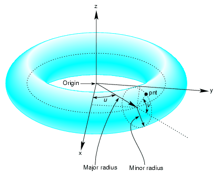
The pfTorusSurface class provides methods to describe a torus. Figure 9-13 illustrates a torus, and how it is parameterized in pfTorusSurface.
A torus can be defined geometrically as the surface in space that is swept by moving a circle, the minor circle, through space such that its center lies on a second circle, the major circle, and the planes of the two circles are always perpendicular to each other, with the plane of the minor circle aligned along radii of the major circle. The parametrization of the surface is that u represents a position on the major circle and v represents a position on the minor circle.
The class has the following main methods:
class pfTorusSurface : public pfParaSurface
{
public:
// Creating and destroying
pfTorusSurface( );
pfTorusSurface( pfReal majorRadius, pfReal minorRadius );
virtual ~pfTorusSurface();

// Accessor functions
void setMajorRadius(  pfReal majorRadiusVal );
void setMinorRadius( pfReal minorRadiusVal );
pfReal getMajorRadius( ) const;
pfReal getMinorRadius( ) const;

// Evaluators
virtual void evalPt(   pfReal  u, pfReal v, pfRVec3 &pnt );
virtual void evalNorm( pfReal  u, pfReal v, pfRVec3 &norm );
}
|
The constructor pfTorusSurface( majorRadius, minorRadius ) defines a torus with the specified radii such that the major circle is in the x-y plane and the minor circle is initially in the x-z plane. The default value for the major radius is 1; the default for the minor radius is 0.1.
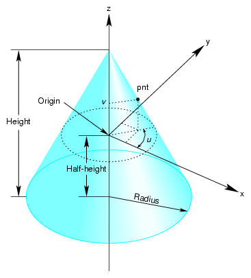
You can define a cone geometrically by sweeping a circle along an axis in a way similar to the way a cylinder is defined; however, as the circle is swept along the axis, the radius changes linearly with distance.
The parameterization of a point on an pfConeSurface is that u measures the angle, in radians, of the point on the circle, and that v measures the distance along the axis from the origin. To truncate a cone, yielding a frustum, adjust the value for v.
The class has the following main methods:
class pfConeSurface : public pfParaSurface
{
public:
// Creating and destroying
pfConeSurface( void );
pfConeSurface( pfReal radius, pfReal height );
virtual ~pfConeSurface();

// Accessor functions
void setRadius( pfReal radius ) ;
void setHeight( pfReal height );
pfReal getRadius( ) const;
pfReal getHeight( ) const;

// Evaluators
void evalPt(   pfReal  u, pfReal v, pfRVec3 &pnt );
void evalNorm( pfReal  u, pfReal v, pfRVec3 &norm );
}
|
The constructor pfConeSurface( radius, height ) creates a parametric cone with the specified height and a circular base with the specified radius. By default, the base of the cone is parallel to the x-y plane and centered on the z axis and the apex of the cone is on the positive z-axis. The cone extends from the origin in the positive and negative z directions for one half the height. The default for the radius of the base is 1 and the default height is 2.
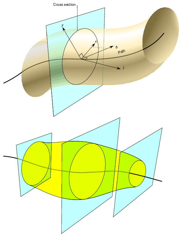
The class pfSweptSurface provides methods to describe a general swept surface. Three examples of swept surfaces have been presented: a cylinder, a torus, and a cone. In the first two cases a simple cross-section, a circle of constant radius, was swept along a path. For a cone, the radius of the circle varied according to a simple profile.
To describe a swept surface, you specify a path, a cross section, and a coordinate frame in which the graph of the cross section is drawn at each point on the path. The parameterization of the surface is that u denotes the position along the path and v denotes the position on the cross-section curve. You can also specify a profile, which adjusts the size of the cross-section curve. Thus, for example, with a simple profile method you could generate a sphere from a straight-line path and a circular cross section. Figure 9-15 illustrates the feature of a swept surface.
Unlike the examples of the cylinder, torus, and cone, the cross-section in an pfSweptSurface generally is not necessarily perpendicular to the path. You set the orientation of the cross-section with two additional instances of pfCurve3d. For a point on the path corresponding the parameter value t0, the vectors on these two additional curves that have the same parameter value define the local coordinate system used to draw the profile: one vector defines the normal to the plane of the graph, the second the x axis for the graph, and their cross product determines the direction of the y axis for the graph. For more details, see the discussion of the constructor below.
The class has the following main methods:
class pfSweptSurface : public pfParaSurface
{
public:
// Creating and destroying
pfSweptSurface( void );
pfSweptSurface( pfCurve3d *crossSection,
                pfCurve3d *_path,
                pfCurve3d *_t,
                pfCurve3d *_b,
                pfScalar  *_profile  );
virtual ~pfSweptSurface( );

// Accessor functions
void setCrossSection( pfCurve3d *_crossSection );
void setPath( pfCurve3d *_path );
void setT( pfCurve3d *_tng );
void setB( pfCurve3d *_b );
void setProf( pfScalar  *_profile );
pfCurve3d *getCrossSection() const;
pfCurve3d *getPath() const;
pfCurve3d *getT() const;
pfCurve3d *getB() const;
pfScalar  *getProf()const;

virtual void evalPt( pfReal u, pfReal v, pfRVec3 &pnt );
};
|
| pfSweptSurface( crossSection, path, t, b, profile ) | Defines a swept surface with the given path, cross section, and profile. The arguments t and b are vector-valued functions of the path's parameter. They define the orientation of the profile at each point on the path. The orientation at a particular point on the curve is determined by rendering the graph of crossSection in the coordinate plane perpendicular to t, which locally defines the z axis of an x-y-z coordinate system. The x axis is defined by the projection of b onto the plane, and the y axis forms a right-hand coordinate system with the other two axes. The cross section is plotted in the x-y plane. If you specify a NULL value for profile, crossSection does not vary along path. | |
| evalPt( u, v, pnt ) | Calculates the point on the surface, pnt, as the vector sum of (a) the point on the path corresponding to the value u and (b) the point on the cross section corresponding to the value v. The vector locating the point on the cross section is scaled by the value at u of the profile function, if profile is not NULL. |
As a convenience, the class pfFrenetSweptSurface allows you to use the Frenet frame of the path to define the orientation vectors in a swept surface. The Frenet frame is defined by the three unit vectors derived from the tangent, the principal normal, and their cross product. This set of vectors facilitates orienting the cross section perpendicularly to the path at every point.
| Note: The path for an pfFrenetSweptSurface must be at least a cubic to allow for the principal normal calculation, which requires a second derivative. |
The class has the following main methods:
class pfFrenetSweptSurface : public pfSweptSurface
{
public:
// Accessor functions
pfFrenetSweptSurface( void );
pfFrenetSweptSurface( pfCurve3d *crossSection,
                      pfCurve3d *path,
                      pfScalar  *profile  );
virtual ~pfFrenetSweptSurface( );

// Accessor functions
void set( pfCurve3d *crossSection,
          pfCurve3d *path,
          pfScalar  *profile  );
};
|
The arguments of the constructor for pfFrenetSweptSurface are the same as for pfSweptSurface and have the same effects, except for the orientation vectors, which are set to be the tangent and principal normal to path, and so do not appear as arguments. Use the inherited method evalPt() to locate points on the surface.
The following code uses an pfFrenetSweptSurface to define a torus whose minor radius varies with position on the ring. Other instances of pfFrenetSweptSurface appear in repTest.
// Scalar curve used by the swept surface primitive
static pfReal profile( pfReal t )
{
return 0.5*cos(t*5.0) + 1.25;
};

pfCircle3d  *cross =
                    new pfCircle3d( 0.75, new pfRVec3( 0.0, 0.0, 0.0) );
pfCircle3d  *path  =
                    new pfCircle3d( 1.75, new pfRVec3( 0.0, 0.0, 0.0) );
pfFrenetSweptSurface *fswept =
                      new pfFrenetSweptSurface( cross, path, profile );
fswept->setHandednessHint( TRUE );
|
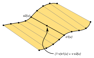
A ruled surface is generated from two curves in space, both parameterized by the same variable, u. A particular value of u specifies a point on both curves. A ruled surface is defined by connecting the two points with a straight line parameterized by v. The parameterization of the resulting surface is always the unit square in the UV plane, regardless of the parameterizations of the original curves.
A bilinear interpolation of four points is perhaps the simplest example of a ruled surface, one for which the “curves” that define the surface are in fact straight lines. Thus, you connect two pairs of points in space with lines and then develop the ruled surface. For a bilinear interpolation, the parameterization by u and v is such that, if one of them is held constant, a point “moves” along the connecting straight line at a uniform speed as the other parameter is varied.
The class has the following main methods:
class pfRuledSurface : public pfParaSurface
{
public:
// Creating and destroying
pfRuledSurface();
pfRuledSurface( pfCurve3d *c1, pfCurve3d *c2 );
virtual ~pfRuledSurface();
// Accessor functions
void setCurve1( pfCurve3d *_c1 );
void setCurve2( pfCurve3d *_c2 );
pfCurve3d *getCurve1( ) const;
pfCurve3d *getCurve2( ) const;

// Evaluators
void evalPt(   pfReal  u, pfReal v, pfRVec3 &pnt );
};
|
The constructor pfRuledSurface( c1, c2 ) creates an instance of a ruled surface defined by the two curves c1 and c2.
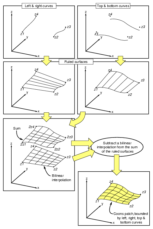
A Coons patch is arguably the simplest surface you can define from four curves whose endpoints match and form a closed loop. Think of the four curves as defining the four sides of the patch, with one pair on opposite sides of the patch defining the top and bottom curves and the other pair defining the left and right curves (see Figure 9-17). The top and bottom curves are parameterized by u, and the left and right curves by v. Thus, u is the “horizontal” coordinate and v the “vertical” coordinate.
The patch is made by
Adding the points on the ruled surface defined by the top and bottom curves to the points on the ruled surface defined by the left and right curves.
Subtracting the bilinear interpolation of the four corner points.
Figure 9-17 illustrates the construction. To understand the result, notice that, after you add the two ruled surfaces, each side of the boundary of the resulting surface is the sum of the original bounding curve and the straight line connecting the bounding curve's endpoints. The straight line was introduced by the construction of the ruled surface that did not include the boundary curve. Subtracting the bilinear interpolation eliminates the straight-line components of the sum, leaving just the original four curves as the boundary of the resulting surface.
The class has the following main methods:
class pfCoonsSurface : public pfParaSurface
{
public:
pfCoonsSurface( );
pfCoonsSurface( pfCurve3d *right,   pfCurve3d *left,
         pfCurve3d *bottom,  pfCurve3d *top );
virtual ~pfCoonsSurface( );

// Accessor functions
void setRight(  pfCurve3d *right );
void setLeft( pfCurve3d *left );
void setBottom( pfCurve3d *bottom );
void setTop( pfCurve3d *top );

pfCurve3d* getTop() const;
pfCurve3d* getBottom() const;
pfCurve3d* getLeft() const;
pfCurve3d* getRight() const;

// Surface point evaluator
void evalPt( pfReal u, pfReal v, pfRVec3 &pnt );
};
|
The constructor pfCoonsSurface( right, left, bottom, top ) creates an instance of a Coons patch defined by the four curves right, left, bottom, and top. The top and bottom curves are parameterized by u and the left and right curves are parameterized by v.
Just as a NURBS curve consists of Bezier curves, a NURBS surface consists of Bezier surfaces. The set of control parameters is essentially the same for the curves and surfaces: a set of knots, a control hull, and a set of weights. However, for a NURBS surface, the knots form a grid in the coordinate system of the surface; that is, in the u-v plane, and the control hull is a grid of points in space that loosely defines the surface.
Understanding a Bezier surface helps you understand and use a NURBS surface. A Bezier surface is defined essentially as the surface formed by sweeping a Bezier cross section curve through space, along a path defined by a Bezier curve. But, unlike an pfSweptSurface, the shape of the cross-section can be changed.
You define a Bezier surface as follows:
Start with a Bezier curve in space: the cross section parameterized by u.
Define a family of Bezier curves, a set of paths all of which are parameterized by v, that start at the control points of the initial cross section.
For each value of v, the set of control points defines a Bezier curve. As v changes, the cross-sectional curve “moves” through space, changing shape and defining a Bezier surface.
A NURBS surface joins Bezier surfaces in a smooth way, similar to NURBS curves joining Bezier curves. The class pfNurbSurface provides methods to describe a NURBS surface.
The class has the following main methods:
class pfNurbSurface : public pfParaSurface
{
public:
// Creating and destroying
pfNurbSurface( void );
virtual ~pfNurbSurface( );

// Accessor functions
void setControlHull( int iu, int iv, const pfRVec3 &p );
void setControlHull( int iu, int iv, const pfRVec4 &p );
void setWeight( int iu, int iv, pfReal w );
void setUknot( int iu, pfReal u );
void setVknot( int iv, pfReal v );
void setControlHullUSize( int s );
void setControlHullVSize( int s );

// Get the same parameters
pfRVec3& getControlHull( int iu, int iv) ;
int     getControlHullUSize( void );
int     getControlHullVSize( void );
pfReal  getWeight( int iu, int iv)
pfReal  getUknot( int iu);
pfReal  getVknot( int iv);
int     getUknotCount( void );
int     getVknotCount( void );
int     getUorder( void ) ;
int     getVorder( void ) ;
void    removeControlHullElm(int ui, int iv);
void    removeUknot(int iu);
void    removeVknow(int iv);
void    flipUV();

// Evaluator
virtual void evalPt(   pfReal u, pfReal v, pfRVec3 &pnt );
virtual void evalDu(   pfReal u, pfReal v, pfRVec3 &Du );
virtual void evalDv(   pfReal u, pfReal v, pfRVec3 &Du );
virtual void evalNorm( pfReal u, pfReal v, pfRVec3 &norm );
};
|
The member functions are essentially the same as those for pfNurbCurve3d (see “NURBS Curves in Space”), however:
The hull is a grid of pfRVec3s indexed by i and j.
The set of knots is defined by points on the u and v axes.
There are B-spline basis functions (of possibly differing orders) associated with each coordinate direction.

Note: pfNurbSurface redefines the virtual evaluators inherited from pfParaSurface for tangent and normal vectors; the methods use the NURBS equation rather than finite, central differences.
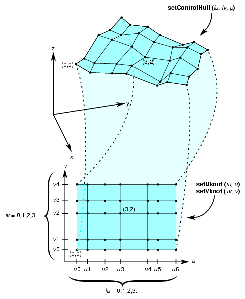
Indexing of knot points in coordinate space and control hull points in three-dimensional space is illustrated in Figure 9-18. The indexing works as for gluNurbsSurface, that is, as follows:
iu indexes knots on the u axis. The correspondence is established by setUknot().
iv indexes knots on the v axis.The correspondence is established by setVknot().
Each (iu,iv) thus indexes a knot point in the u-v plane.
Each (iu,iv) also indexes a point on the control hull in three-dimensional space. The correspondence is established by setControlHull().
Thus, setUknot(), setVknot(), and setControlHull() establish a correspondence between an index pair (iu,iv) a knot point (uiu viv), and a point on the control hull in three-dimensional space.
Indexing is determined by the following equation that OpenGL Performer uses to calculate a NURBS surface (the index i corresponds to iu in the API, and j corresponds to iv):
 |
A NURBS surface can also be developed from the following alternative expression:
 |
For this case, you must change the coordinates of the control points to get the same surface from OpenGL Performer. You convert the coordinates of the control points from (x,y,z,w) to (wx,wy,wz,w).
The following code fragment form the repTest sample application illustrates an instance of an pfNurbSurface. Toward the end of the example, an optional pfNurbCurve2d trim curve is created.
int i, j;

pfNurbSurface *nurb = new pfNurbSurface;

// Control hull dimensions
#define USIZE 4
#define VSIZE 5

// Set up the control hull size because we know a priori how big
// the nurb is.  The next two lines are used for space
// efficiency but are functionally unnecessary.
nurb->setControlHullUSize(USIZE);
nurb->setControlHullVSize(VSIZE);

// Make the control hull be an oscillating grid
for ( i = 0; i < VSIZE; i++ )
{
pfReal y = i/(float)(VSIZE - 1) * 2*M_PI - M_PI;

for ( j = 0; j < USIZE; j++ )
{
pfReal x = j/(float)(USIZE - 1) * 2*M_PI - M_PI;
pfReal val = 6*pow( cos(sqrt(x*x + y*y)), 2.0);

// Make the control hull a box, j maps to u and i maps to v
nurb->setControlHull( i, j, pfRVec3( x, y, val));

// Add the weights
nurb->setWeight( i, j, 1.0 );
}
}

// Add the knot points
nurb->setUknot( 0,  0.0 );
nurb->setUknot( 1,  0.0 );
nurb->setUknot( 2,  0.0 );
nurb->setUknot( 3,  0.0 );
nurb->setUknot( 4,  1.0 );
nurb->setUknot( 5,  1.0 );
nurb->setUknot( 6,  1.0 );
nurb->setUknot( 7,  1.0 );

nurb->setVknot( 0,  0.0 );
nurb->setVknot( 1,  0.0 );
nurb->setVknot( 2,  0.0 );
nurb->setVknot( 3,  0.0 );
nurb->setVknot( 4,  1.0 );
nurb->setVknot( 5,  1.0 );
nurb->setVknot( 6,  1.0 );
nurb->setVknot( 7,  1.0 );

// Only trim reps in the first row
if ( nVersions <= 0 )
{
// Add a super quadric trim curve
pfSuperQuadCurve2d  *trimCircle0 = new pfSuperQuadCurve2d( 0.25, new pfRVec2(0.25, 0.50), 2.0 );
nurb->addTrimCurve( 0, trimCircle0, NULL );

// make a 4-th order nurb trim curve
pfNurbCurve2d *l = new pfNurbCurve2d;

l->setKnot(0,0.0);
l->setKnot(1,0.0);
l->setKnot(2,0.0);
l->setKnot(3,0.0);
l->setKnot(4,1.0);
l->setKnot(5,1.0);
l->setKnot(6,1.0);
l->setKnot(7,1.0);
l->setControlHull(0,pfRVec2(0.50,0.50));
l->setControlHull(1,pfRVec2(0.90,0.10));
l->setControlHull(2,pfRVec2(0.90,0.90));
l->setControlHull(3,pfRVec2(0.50,0.50));

nurb->addTrimCurve( 1, l, NULL  );
}
|
Hermite-spline surfaces interpolate a grid of points; that is, they pass through the set of specified points under the constraint that you supply the tangents at each point in the u and v directions and the mixed partial derivative at each point. This surface definition is the natural generalization of Hermite-spline curves, discussed in “Hermite-Spline Curves in the Plane”.
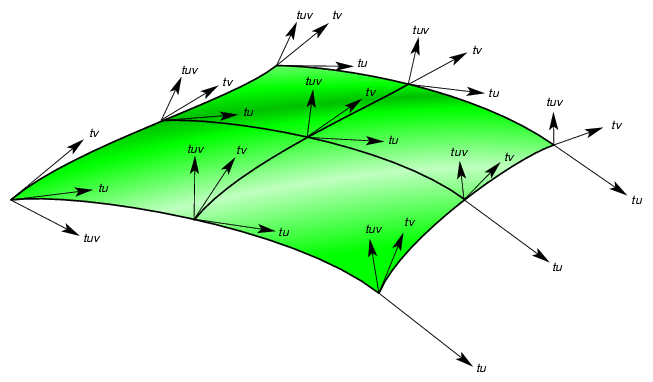
Hermite-spline surfaces are made of Hermite patches (see Figure 9-19). A bicubic Hermite patch expands the definition of a bilinear interpolation to include specification of first derivatives and mixed partial derivatives of the surface at each of the four corners. The adjective “bicubic” in the name of the patches refers to the mathematical definition, which includes products of the cubic Hermite polynomials that define a Hermite-spline curve.
An advantage of including the derivatives to constrain the surface is that it is simple to combine the patches into a smooth composite surface, that is, into a Hermite-spline surface.
The class has the following main methods:
class pfHsplineSurface : public pfParaSurface
{
public:
// Creating and destroying
pfHsplineSurface();
pfHsplineSurface( pfReal *_p,
                  pfReal *_tu,  pfReal *_tv, pfReal *_tuv,
                  pfReal *_uu, pfReal *_vv,
                  int uKnotCount, int vKnotCount );
virtual ~pfHsplineSurface();

// Accessor functions
pfRVec3& getP( int i, int j );
pfRVec3& getTu( int i, int j );
pfRVec3& getTv( int i, int j );
pfRVec3& getTuv( int i, int j );
pfReal  getUknot( int i );
pfReal  getVknot( int j );
int     getUknotCount();
int     getVknotCount();
pfBool  getCylindrical();

void setAll( pfReal *p,
             pfReal *tu,
             pfReal *tv,
             pfReal *tuv,
             pfReal *uu,
             pfReal *vv,
             int uKnotCount,
             int vKnotCount );
void setCylindrical( pfBool cylinderical );

// Surface point evaluator
void evalPt( pfReal u, pfReal v, pfRVec3 &pnt );
};
|
The pfHsplineSurface class has two important methods, the constructor and set/getCylinderical().
The pfHsplineSurface constructor has the following arguments:
| _p | Specifies the grid of points on the surface. | |
| _tu, _tv, and _tuv | Specify, respectively, the corresponding tangents in the u and v directions and the mixed partials. The indexing of each of the arrays _p, _tu, _tv, and _tuv is as follows: the x, y, and z components of each vector are grouped in that order, and the sequence of points is defined so that the vKnotCount index changes more rapidly. | |
| uKnotCount and vKnotCount | Specify the number of points in the grid. The surface is made of (uKnotCount-1) ¥ (vKnotCount-1) Hermite patches. | |
| _uu and _vv | Define the knot points, the parameter values corresponding to the patch corners; thus, they have uKnotCount and vKnotCount elements, respectively. | |
| setCylindrical() and getCylindrical() | Control the flag for whether the coordinates and derivatives are assumed to be in cylindrical coordinates. |
A mesh, encapsulated in OpenGL Performer by the high-level class pfMesh, is used to store information about the topology of an object. A pfMesh is derived from a pfObject for memory allocation purposes. A pfMesh stores the object as a collection of vertices and flat faces (a vertex being encapsulated as a pfMeshVertex and a face as a pfMeshFace). It is possible to query the mesh to determine the information about neighbors of a given vertex or a face. This information is required by various algorithms—for example, for evaluating subdivision surfaces or for simplification of objects.
You can build a pfMesh for a given object in several ways:
You can use the function pfdAddNodeToMesh() that parses a given node and adds all its geometry to the mesh.
You can write your own traverser and for each pfGeoSet you can call the function pfMeshAddGeoSet().
You can call the function pfMeshAddTriangle() or pfMeshAddFace() and add each face separately.
Where you would like to have full control over the topology stored in the pfMesh, you can directly set the array of faces and vertices. To do that, you can create the corresponding arrays by calling pfMeshNumFaces() and pfMeshNumVertices() and then set each face and vertex separately. You can get the pointer to the array item by calling the function pfGetMeshVertex() and pfGetMeshFace(), respectively.
When using the function pfMeshAddGeoSet(), you can specify the pfGeoSet, the number of a mesh part, and the current transformation. The information about parts can be used to mark edges. Each edge is automatically marked with the following flags:
| Flag | Description | |
| PFM_EDGE_NORMAL | An edge with two adjacent faces | |
| +PFM_EDGE_BOUNDARY | An edge with one adjacent face to the left of the edge | |
| –PFM_EDGE_BOUNDARY | An edge with one adjacent face to the right of the edge | |
| PFM_EDGE_SPLIT | An edge with more than one adjacent face (in the case of non-manifold surfaces). |
You can mark edges between different parts as PFM_EDGE_CREASE if the flag PFM_FLAG_CREASES_BETWEEN_PARTS, described later in this section, is set. Note that edges between faces with different pfGeoStates are also usually marked as creases.
The part index and the transformation is also provided to functions pfMeshAddTriangle() and pfMeshAddFace(). In addition, you also need to set the pfGeoState of the triangle or face.
When setting vertices and faces directly and accessing them through a pointer, you need to set all vertex and face parameters. See the later sections “Mesh Faces” and “Mesh Vertices”.
You must call the function pfMeshSplitVertices() after all vertices are set, regardless of the method used to build the mesh. This function performs extra post-processing that cleans the mesh in cases where the object is not a manifold (see section “Mesh Vertices” for more details).
You can set the following flags to 0 or 1:
You can set the following values:
| Value | Description | |
| PFM_EPSILON | Sets the epsilon to be used when comparing vertices. The default is 1e-6 or if the grid is defined, 1e-6 multiplied by a ratio of the grid diameter to the grid resolution along X axis. | |
| PFM_VERTEX_GRID_SIZE_X | See the description for flag PFM_VERTEX_GRID_SIZE. | |
| PFM_VERTEX_GRID_SIZE_Y | See the description for flag PFM_VERTEX_GRID_SIZE. | |
| PFM_VERTEX_GRID_SIZE_Z | See the description for flag PFM_VERTEX_GRID_SIZE. | |
| PFM_VERTEX_GRID_SIZE | Sets the resolution of the grid used for comparing vertices. You can set the grid size one value at the time or all three coordinates at once. The default grid size is 32x32x32. |
You can also query the bounding box of the mesh using the function pfGetMeshBbox(). This bounding box is computed automatically around the mesh vertices.
You can use the function pfMeshUpdateMesh() to automatically detect which vertices have been changed and to mark them and the corresponding faces. This can be used in case of dynamically controlled meshes (see the section “Subdivision Surfaces” for an example). Since each vertex stores both the pointer to the original vertex location and the vertex coordinates, any changes can be easily detected by comparing these values.
OpenGL Performer uses mesh faces and its vertices to describe a mesh, which in turn describes the topology of an object. The high-level class pfMeshFace encapulsates a face. Each face contains the following:
An array of face vertices
The class pfMeshVertex represents a vertex. You can use the functions pfMeshFaceNumVerts() and pfMeshFaceVertex() to set face vertices. The parameters of the function pfMeshFaceVertex() are the vertex index in the array stored with the face (which vertex you want to set) and the vertex index in the array of vertices associated with a pfMesh. The latter index identifies the vertex. You can use the functions pfGetMeshFaceNumVerts() and pfGetMeshFaceVertex() to query face vertices.A set of texture coordinates
You can use the function pfMeshFaceTexCoord() to specify texture coordinates as vertices.A pfGeoSet
A part index
The part index is used by the pfMesh to determine which edges are marked as smooth and which, as creases (see the preceding section “Meshes”)Flags
There is only one flag used by a pfMeshFace: PFMF_FLAG_FACE_CHANGED. You set this flag with the function pfMeshUpdateMesh() to indicate that a vertex of the face has changed position.
A pfMeshVertex is a high-level OpenGL Performer class used in a pfMesh to store information about vertices. A pfMeshVertex stores the following:
Vertex coordinates
The pointer to the original vertex coordinates (to be able to detect local changes in the mesh)
An array of vertex neighbors
A set of binary flags
An index of another vertex at the same location (used for non-manifolds,as described later in the subsection “Vertex Neighbors”)
This section describes these items in the following subsections:
You can use the functions pfMeshVertexCoord() and pfMeshVertexCoordPtr() to set the vertex coordinates and the pointer to the original coordinates. The value set by pfMeshVertexCoord() should correspond to the value at the location set by pfMeshVertexCoordPtr(). If the specified pointer is NULL (for example, where a pfGeoSet was under a pfSCS node), it is not possible to automatically detect changes in position of vertices and you must modify all vertices manually by calling the function pfMeshVertexCoord(). If you do not plan to animate the mesh, you can set the pointer to NULL.
Each vertex stores an array of its neighbors. You can query the neighbors using the functions pfMeshVertexNumNeighbors() and pfMeshVertexNeighbor(). The structure of pfMeshVertexNeighbor() is defined in pf.h as follows:
typedef struct
{
    int vertex;
    int face;
    short int edgeType;
    short int next, prev;
} pfMeshVertexNeighbor;
|
This structure consists of the vertex index (in the array of vertices in pfMesh), face index (in the array of faces in pfMesh), edge type, and index of the next and previous neighbor in the array of neighbors.
The edge can be one of the following types:
| Edge Type | Description | |
| PFM_EDGE_NORMAL | Specifies a smooth edge with two adjacent faces. | |
| PFM_EDGE_CREASE | Specifies a sharp edge with two adjacent faces. | |
| +PFM_EDGE_BOUNDARY | Specifies an edge with one adjacent face to the left of the edge. | |
| –PFM_EDGE_BOUNDARY | Specifies an edge with one adjacent face to the right of the edge. |
The pertinent face is the face to the left of the edge (unless the edge is marked as –PFM_EDGE_BOUNDARY). The next neighbor is part of this face and the previous neighbor is part of the face to the right. If the edge is of type –PFM_EDGE_BOUNDARY, the next neighbor points to the corresponding edge of type +PFM_EDGE_BOUNDARY and the previous neighbors of the edge of type +PFM_EDGE_BOUNDARY point to the the corresponding edge of type +PFM_EDGE_BOUNDARY. Note that in the case of manifolds each vertex has exactly zero or two boundary edges.
In the case of arbitrary surfaces, there may be more than one loop of neighbors (if you follow the next links). That is why the class pfMesh provides the function pfMeshSplitVertices(), which splits each vertex where the surface behaves as non-manifold. The vertex is split into several vertices, each having a single loop of ordered neighbors and the same position.
You can access the next and previous neighbor for a given neighbor with vertex indexed v1 by calling the functions pfPreviousNeighborMeshVertex() and pfNextNeighborMeshVertex(). You can also determine the index of such a neighbor in the array of neighbors by calling pfPreviousNeighborIndexMeshVertex() and pfNextNeighborIndexMeshVertex().
The following flags can be set for each pfMeshVertex:
| Flag | Description | |
| PFMV_FLAG_VERTEX_CHANGED | Set by the function pfMeshUpdateMesh() when the coordinate stored at the vertex does not match the value at the coordinate pointer. | |
| PFMV_FLAG_VERTEX_NEIGHBOR_CHANGED | Set by the function pfMeshUpdateMesh() when the position of any neighbor changes. | |
| PFMV_FLAG_VERTEX_FACE_CHANGED | Set by the function pfMeshUpdateMesh() when the position of any vertex on any of the faces associated with this vertex changes. | |
| PFMV_FLAG_VERTEX_SPLIT | Set by the function pfMeshSplitVertices() when the surface around the vertex is not manifold and the vertex is split into several vertices (see the preceding section “Vertex Neighbors”). |
A subdivision surface is specified by a control mesh consisting of a set of connected faces (usually triangles or quads). The control mesh is stored as a pfMesh. The OpenGL Performer class pfSubdivSurface is used to define a subdivision surface.
Before rendering a subdivision surface, each face is recursively subdivided into a finer mesh. For example, in the case of Loop subdivision, each triangle is subdivided into four new triangles at each subdivision step. The positions of both original vertices and newly introduced vertices are determined by the subdivision rules. Usually the position is a linear combination of the positions of the original vertices of the face and the vertices of neighboring faces. The parameters of the linear combination are set in a such a way that, after a few subdivision steps, the resulting mesh smooths sharp edges. For example, if the control mesh is a tetrahedron after a few subdivision steps, you get an oval shape. Optionally, it is possible to mark selected edges not to be smooth. An excellent source of information on subdivision surfaces is the SIGGRAPH 2000 course "Subdivision for Modeling and Animation" (http://mrl.nyu.edu/publications/subdiv-course2000/).
The remainder of this section describes the following topics:
The function pfSubdivSurface() creates and returns a handle to a pfSubdivSurface. Like other pfNodes, pfSubdivSurfaces are always allocated from shared memory and cannot be created statically on the stack or in arrays. Use the function pfDelete() rather than the delete operator to delete pfSubdivSurfaces.
To define a subdivision surface, you must specify its control mesh using the function pfSubdivSurfaceMesh(). The mesh is stored as a pfMesh. A pfMesh is a data structure that stores the connectivity between individual faces of the mesh. For each vertex and face, you can access neighboring vertices and faces, respectively. See the preceding section “Meshes” for more details.
To create a pfMesh, you can either specify its faces and the connectivity one by one or use the function pfdAddNodeToMesh(). This function takes a pfNode, parses all its pfGeoSets, splits all primitives into planar faces, and adds those faces into the specified pfMesh (see the pfdAddNodeToMesh man page).
Before you set the mesh using pfSubdivSurfaceMesh(), you need to set various parameters of the subdivision because different internal data structures may be needed for different types of subdivision. You use the function pfSubdivSurfaceVal() to set the values and the function pfSubdivSurfaceFlags() to set the flags.
You can set the following values:
You can set the following flags to 0 or 1:
| Flag | Description | |
| PFSB_GPU_SUBDIVISION | Allows direct evaluation of the surface on the graphics hardware (GPU) if set to 1. The hardware must support floating point fragment shaders (for example, Onyx4 or Prism systems). The default is 0. | |
| PFSB_CONTROL_VERTICES_DYNAMIC | Allows the modification of the vertices of the control surface (only their position) on the fly. See the later subsection “Dynamic Modification of Vertices” for more information. The default is 0. | |
| PFSB_USE_GEO_ARRAYS | Stores the resulting subdivided mesh (in the case of software evaluation) in pfGeoArrays. Otherwise, regular pfGeoSets are used. The default is 1. |
The following examples set up a subdivision surface and add it into a scene.
Example 1:
pfSubdivSurface *subdivSurface;
pfMesh          *mesh;

subdSurf = pfNewSubdivSurface(arena);
mesh = pfNewMesh(arena);
if(method == PFSB_LOOP)
    pfMeshFlags(mesh, PFM_FLAG_TRIANGULATE, 1); // important!

pfdAddNodeToMesh(root, mesh, 0); // part 0

pfSubdivSurfaceVal(subdSurf, PFSB_SUBDIVISION_LEVEL, subdivLevel);
pfSubdivSurfaceVal(subdSurf, PFSB_SUBDIVISION_METHOD, method);
pfSubdivSurfaceFlags(subdSurf, PFSB_GPU_SUBDIVISION, GPUsubdivision);
|
Example 2:
pfSubdivSurfaceMesh(subdSurf, mesh);
pfAddChild(scene, subdSurf);

pfSubdivSurface *subdivSurface = new pfSubdivSurface;

pfMesh *mesh = new pfMesh;
if(method == PFSB_LOOP)
    mesh->setFlags(PFM_FLAG_TRIANGULATE, 1); // important!

pfdAddNodeToMesh(root, mesh, 0); // part 0

subdivSurface->setVal(PFSB_SUBDIVISION_LEVEL, subdivLevel);
subdivSurface->setVal(PFSB_SUBDIVISION_METHOD, method);
subdivSurface->setFlags(PFSB_GPU_SUBDIVISION, GPUsubdivision);

subdivSurface->setMesh(mesh);

scene->addChild(subdivSurface);
|
You can find sample code in the file perf/samples/pguide/libpf/C++/subdivSurface.C. or in the file %PFROOT%\Src\pguide\libpf\C++\subdivSurface.cxx on Microsoft Windows.
The major difference between Loop subdivision and Catmull-Clark subdivision is in the type of faces they process. Loop subdivision operates exclusively on triangles. Therefore, the control mesh has to be triangulated. Since a pfMesh does not know whether it is used in a pfSubdivSurface and what subdivision method is used, you must set the flag PFM_FLAG_TRIANGULATE on the pfMesh before specifying the faces (see the sample code in the preceding section “Creating a Subdivision Surface”).
Catmull-Clark subdivision, on the other hand, operates on quads. If the control mesh contains non-quads, the first subdivision step is performed using special rules so that an arbitrary face is divided into a set of quads. Note that this step cannot be performed on a GPU. This step introduces some discontinuities in the second derivative of the curvature. Consequently, the surface may appear more bumpy around the edges of the original control faces. For this reason, start with a control mesh containing only quads for optimal results. The advantage of Catmull-Clark subdivision is that it is supported by many modeling tools, including Maya.
If the flag PFSB_CONTROL_VERTICES_DYNAMIC is set, you can modify the position of vertices of the control mesh to animate the surface. You need to call the function pfSubdivSurfaceUpdateControlMesh() at each frame to confirm the changes. Note that you cannot have in the node any tranforms specifying the control mesh.
You can subdivide an arbitrary file loaded into OpenGL Performer by using the libpfsubdiv pseudo loader. It works similarly as the libpftrans or libpfscale pseudo loader. Suppose that you want to subdivide truck.pfb in Perfly. You enter the following command:
perfly truck.pfb.0,2,0.subdiv |
The syntax of the libpfsubdiv loader is as follows:
<filename>.<method>,<subdivLevel>,<GPUon>.subdiv
The value for method is 0 for Catmull-Clark and 1 for Loop subdivision. The subdivLevel value is usually around 2 and GPUon is 1 if the evaluation should be done fully on a GPU.
Note the following limitations and anomalies regarding the use of subdivision surfaces:
Subdivision level 0 may result in incorrect normals.
Currently, the GPU subdivision supports only control meshes with vertices that have less than 11 neighbors.
Current drivers on Onyx4 , Prism, and Microsoft Windows platforms do not support super buffers. Therefore, the GPU evaluation of subdivision surfaces on those systems is too slow.
