This chapter explains how to use the different OpenGL texturing extensions. The extensions are discussed in alphabetical order, by extension name:
The following sections describe extensions that are experimental:
The 3D texture extension, EXT_texture3D, defines 3-dimensional texture mapping and in-memory formats for 3D images, and adds pixel storage modes to support them.
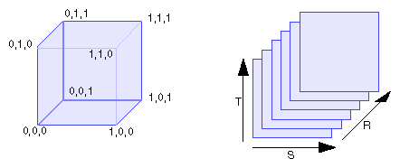
3D textures can be thought of as an array of 2D textures, as illustrated in Figure 7-1.
A 3D texture is mapped into (s,t,r) coordinates such that its lower left back corner is (0,0,0) and its upper right front corner is (1,1,1).
3D textures are useful for
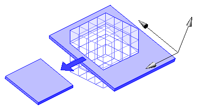
Texel values defined in a 3D coordinate system form a texture volume. You can extract textures from this volume by intersecting it with a plane oriented in 3D space, as shown in Figure 7-2.
The resulting texture, applied to a polygon, is the intersection of the volume and the plane. The orientation of the plane is determined from the texture coordinates of the vertices of the polygon.
To create a 3D texture, use glTexImage3DEXT(), which has the following prototype:
void glTexImage3DEXT( GLenum target,
                           GLint level,
                           GLenum internalformat,
                           GLsizei width,
                           GLsizei height,
                           GLsizei depth,
                           GLint border,
                           GLenum format,
                           GLenum type,
                           const GLvoid *pixels )
|
The function is defined like glTexImage2D() but has a depth argument that specifies how many “slices” the texture consists of.
The extension provides the following additional features:
Pixel storage modes. The extension extends the pixel storage modes by adding eight new state variables:
All four modes default to zero.
Texture wrap modes. The functions glTexParameter*(), accept the additional token value GL_TEXTURE_WRAP_R_EXT.
GL_TEXTURE_WRAP_R_EXT affects the R coordinate in the same way that GL_TEXTURE_WRAP_S affects the S coordinate and GL_TEXTURE_WRAP_T affects the T coordinate. The default value is GL_REPEAT.
Mipmapping. Mipmapping for two-dimensional textures is discussed in the section “Multiple Levels of Detail,” on page 338 of the OpenGL Programming Guide. Mipmapping for 3D textures works the same way: A 3D mipmap is an ordered set of volumes representing the same image; each volume has a resolution lower than the previous one.
The filtering options GL_NEAREST_MIPMAP_NEAREST, GL_NEAREST_MIPMAP_LINEAR, and GL_LINEAR_MIPMAP_NEAREST, apply to subvolumes instead of subareas. GL_LINEAR_MIPMAP_LINEAR results in two trilinear blends in two different volumes, followed by an LOD blend.
Proxy textures. Use the proxy texture GL_PROXY_TEXTURE_3D_EXT to query an implementation's maximum configuration. For more information on proxy textures, see “Texture Proxy” on page 330 of the OpenGL Programming Guide, Second Edition.
You can also call glGetIntegerv() with argument GL_MAX_TEXTURE_SIZE_3D_EXT.
Querying. Use the following call to query the 3D texture:
glGetTexImage(GL_TEXTURE_3D_EXT, level, format, type, pixels)
Subvolumes of the 3D texture can be replaced using glTexSubImage3DEXT() and glCopyTexSubImage3DEXT() (see “Replacing All or Part of a Texture Image,” on pages 332 - 335 of the OpenGL Programming Guide, Second Edition).
The code fragment presented in this section illustrates the use of the extension. The complete program is included in the example source tree.
/*
 * Shows a 3D texture by drawing slices through it.
 */
/* compile: cc -o tex3d tex3d.c -lGL -lX11 */

#include <GL/glx.h>
#include <GL/glu.h>
#include <X11/keysym.h>
#include <stdlib.h>
#include <stdio.h>

static int attributeList[] = { GLX_RGBA, None };

unsigned int tex[64][64][64];

/* generate a simple 3D texture */
static void
make_texture(void) {
    int i, j, k;
    unsigned int *p = &tex[0][0][0];

    for (i=0; i<64; i++) {
        for (j=0; j<64; j++) {
            for (k=0; k<64; k++) {
                if (i < 10 || i > 48 ||
                    j < 10 || j > 48 ||
                    k < 10 || k > 48) {
                    if (i < 2 || i > 62 ||
                        j < 2 || j > 62 ||
                        k < 2 || k > 62) {
                        *p++ = 0x00000000;
                    } else {
                        *p++ = 0xff80ffff;
                    }
                } else {
                    *p++ = 0x000000ff;
                }
            }
        }
    }
}

static void
init(void) {
    make_texture();
    glEnable(GL_TEXTURE_3D_EXT);
    glEnable(GL_BLEND);
    glBlendFunc(GL_SRC_ALPHA, GL_ONE);
    glClearColor(0.2,0.2,0.5,1.0);
    glPixelStorei(GL_UNPACK_ALIGNMENT, 1);

    glMatrixMode(GL_PROJECTION);
    gluPerspective(60.0, 1.0, 1.0, 100.0 );
    glMatrixMode(GL_MODELVIEW);
    glTranslatef(0.,0.,-3.0);
    glMatrixMode(GL_TEXTURE);


    /* Similar to defining a 2D texture, but note the setting of the */
    /* wrap parameter for the R coordinate.  Also, for 3D textures   */
    /* you probably won't need mipmaps, hence the linear min filter. */
    glTexEnvf(GL_TEXTURE_ENV, GL_TEXTURE_ENV_MODE, GL_MODULATE);
    glTexParameteri(GL_TEXTURE_3D_EXT, GL_TEXTURE_MIN_FILTER,
                                                         GL_LINEAR);
    glTexParameteri(GL_TEXTURE_3D_EXT, GL_TEXTURE_WRAP_S, GL_CLAMP);
    glTexParameteri(GL_TEXTURE_3D_EXT, GL_TEXTURE_WRAP_T, GL_CLAMP);
    glTexParameteri(GL_TEXTURE_3D_EXT, GL_TEXTURE_WRAP_R_EXT,
                                                          GL_CLAMP);
    glTexImage3DEXT(GL_TEXTURE_3D_EXT, 0, 4, 64, 64, 64, 0,
                    GL_RGBA, GL_UNSIGNED_BYTE, tex);
}

#define NUMSLICES 256

static void
draw_scene(void) {
    int i;
    float r, dr, z, dz;

    glColor4f(1, 1, 1, 1.4/NUMSLICES);
    glClear(GL_COLOR_BUFFER_BIT);
    /* Display the entire 3D texture by drawing a series of quads */
    /* that  slice through the texture coordinate space.  Note that */
    /* the transformations below are applied to the texture matrix, */
    /* not the modelview matrix. */

    glLoadIdentity();
    /* center the texture coords around the [0,1] cube */
    glTranslatef(.5,.5,.5);
    /* a rotation just to make the picture more interesting */
    glRotatef(45.,1.,1.,.5);

    /* to make sure that the texture coords, after arbitrary */
    /* rotations, still fully contain the [0,1] cube, make them span */
    /* a range sqrt(3)=1.74 wide */
    r = -0.87; dr = 1.74/NUMSLICES;
    z = -1.00; dz = 2.00/NUMSLICES;
    for (i=0; i < NUMSLICES; i++) {
        glBegin(GL_TRIANGLE_STRIP);
        glTexCoord3f(-.87,-.87,r); glVertex3f(-1,-1,z);
        glTexCoord3f(-.87, .87,r); glVertex3f(-1, 1,z);
        glTexCoord3f( .87,-.87,r); glVertex3f( 1,-1,z);
        glTexCoord3f( .87, .87,r); glVertex3f( 1, 1,z);
        glEnd();
        r += dr;
        z += dz;
    }
}

/* process input and error functions and main(), which handles window
 * setup, go here.
 */
|
The texture color table extension, SGI_texture_color_table, adds a color lookup table to the texture mechanism. The table is applied to the filtered result of a texture lookup before that result is used in the texture environment equations.
Here are two example situations in which the texture color table extension is useful:
Volume rendering. You can store something other than color in the texture (for example, a physical attribute like bone density) and use the table to map that density to an RGB color. This is useful if you want to display just that physical attribute and also if you want to distinguish between that attribute and another (for example, muscle density). You can selectively replace the table to display different features. Note that updating the table can be faster than updating the texture. (This technique is also called “false color imaging” or “segmentation”).
Representing shades (gamut compression). If you need to display a high color-resolution image using a texture with low color-component resolution, the result is often unsatisfactory. A 16-bit texel with 4 bits per component doesn't offer a lot of shades for each color, because each color component has to be evenly spaced between black and the strongest shade of the color. If an image contains several shades of light blue but no dark blue, for example, the on-screen image cannot represent that easily because only a limited number of shades of blue, many of them dark, are available. When using a color table, you can “stretch” the colors.
To use a texture color table, define a color table, as described in “SGI_color_table—The Color Table Extension”. Use GL_TEXTURE_COLOR_TABLE_SGI as the value for the target parameter of the various commands, keeping in mind the following points:
The table size, specified by the width parameter of glColorTableSGI(), is limited to powers of two.
Each implementation supports a at least a maximum size of 256 entries. The actual maximum size is implementation-dependent; it is much larger on most Silicon Graphics systems.
Use GL_PROXY_TEXTURE_COLOR_TABLE_SGI to find out whether there is enough room for the texture color table in exactly the manner described in “Texture Proxy,” on page 330 of the OpenGL Programming Guide.
The following code fragment loads a table that inverts a texture. It uses a GL_LUMINANCE external format table to make identical R, G, and B mappings.
loadinversetable()
{
    static unsigned char table[256];
    int i;

    for (i = 0; i < 256; i++) {
        table[i] = 255-i;
    }

    glColorTableSGI(GL_TEXTURE_COLOR_TABLE_SGI, GL_RGBA8_EXT,
                    256, GL_LUMINANCE, GL_UNSIGNED_BYTE, table);
    glEnable(GL_TEXTURE_COLOR_TABLE_SGI);
}
|
The contents of a texture color table are used to replace a subset of the components of each texel group, based on the base internal format of the table. If the table size is zero, the texture color table is effectively disabled. The texture color table is applied to the texture components Red (Rt), Green (Gt), Blue (Bt), and Alpha(At) texturing components according to the following table:
Table 7-1. Modification of Texture Components
Base Table Internal Format | Rt | Gt | Bt | At |
|---|---|---|---|---|
GL_ALPHA | Rt | Gt | Bt | A(At) |
GL_LUMINANCE | L(Rt) | L(Gt) | L(Bt) | At |
GL_LUMINANCE_ALPHA | L(Rt) | L(Gt) | L(Bt) | A(At) |
GL_INTENSITY | I(Rt) | I(Gt) | I(Bt) | I(At) |
GL_RGB | R(Rt) | G(Gt) | B(Bt) | At |
GL_RGBA | R(Rt) | G(Gt) | B(Bt) | A(At) |
The texture color table extension is currently implemented on RealityEngine, RealityEngine2, VTX, InfiniteReality, High IMPACT, and Maximum IMPACT systems. For a detailed discussion of machine-dependent issues, see the glColorTableParameterSGI reference page. This section summarizes the most noticeable restrictions.
On Indigo2 IMPACT systems, certain combinations of texture internal format and texture color table internal format do not work, as shown in the following table:
Table 7-2. Unsupported Combinations on Indigo2 IMPACT
TCT | Texture |
|---|---|
GL_RGB | GL_LUMINANCE or GL_LUMINANCE_ALPHA |
GL_RGBA | All formats |
GL_INTENSITY | All formats |
InfiniteReality systems reserve an area of 4K 12-bit entries for texture color tables. Applications can use four 1KB tables, two 2KB tables, or one 4KB table. Not all combinations of texture and texture color tables are legal. InfiniteReality systems support the following combinations:
Table 7-3. Supported Combinations on InfiniteReality
TCT size | TCT Format | Texture |
|---|---|---|
>=1024 | Any | Any |
2048 | L, I, LA | L, I, LA |
4096 | I, L | I, L |
This section discusses the detail texture extension, SGIS_detail_texture, which like the sharpen texture extension (see “SGIS_sharpen_texture—The Sharpen Texture Extension”) is useful in situations where you want to maintain good image quality when a texture is magnified for close-up views.
Ideally, programs should always use textures that have high enough resolution to allow magnification without blurring. High-resolution textures maintain realistic image quality for both close-up and distant views. For example, in a high-resolution road texture, the large features—such as potholes, oil stains, and lane markers that are visible from a distance—as well as the asphalt of the road surface look realistic no matter where the viewpoint is.
Unfortunately, a high-resolution road texture with that much detail may be as large as
2K x 2K, which may exceed the texture storage capacity of the system. Making the image close to or equal to the maximum allowable size still leaves little or no memory for the other textures in the scene.
The detail texture extension provides a solution for representing a 2K x 2K road texture with smaller textures. Detail texture works best for a texture with high-frequency information that is not strongly correlated to its low-frequency information. This occurs in images that have a uniform color and texture variation throughout, such as a field of grass or a wood panel with a uniform grain. If high-frequency information in your texture is used to represent edge information (for example, a stop sign or the outline of a tree) consider the sharpen texture extension (see “SGIS_sharpen_texture—The Sharpen Texture Extension”).
Because the high-frequency detail in a texture (for example, a road) is often approximately the same across the entire texture, the detail from an arbitrary portion of the texture image can be used as the detail across the entire image.
When you use the detail texture extension, the high-resolution texture image is represented by the combination of a low-resolution texture image and a small high-frequency detail texture image (the detail texture). OpenGL combines these two images during rasterization to create an approximation of the high-resolution image.
This section first explains how to create the detail texture and the low-resolution texture that are used by the extension, then briefly looks at how detail texture works and how to customize the LOD interpolation function, which controls how OpenGL combines the two textures.
This section explains how to convert a high-resolution texture image into a detail texture and a low-resolution texture image. For example, for a 2K x 2K road texture, you may want to use a 512 x 512 low-resolution base texture and a 256 x 256 detail texture. Follow these steps to create the textures:
Make the low-resolution image using izoom or another resampling program by shrinking the high-resolution image by 2n.
In this example, n is 2, so the resolution of the low-resolution image is 512 x 512. This band-limited image has the two highest-frequency bands of the original image removed from it.
Create the subimage for the detail texture using subimage or another tool to select a 256 x 256 region of the original high-resolution image, whose n highest-frequency bands are characteristic of the image as a whole. (For example, rather than choosing a subimage from the lane markings or a road, choose an area in the middle of a lane.)
Optionally, make this image self-repeating along its edges to eliminate seams.
Create a blurry version of the 256 × 256 subimage as follows:
First shrink the 256 × 256 subimage by 2n, to 64 × 64.
Then scale the resulting image back up to 256 × 256.
The image is blurry because it is missing the two highest-frequency bands present in the two highest levels of detail.
Subtract the blurry subimage from the original subimage. This difference image—the detail texture—has only the two highest frequency bands.
Define the low-resolution texture (the base texture created in Step 1) with the GL_TEXTURE_2D target and the detail texture (created in Step 5) with the GL_DETAIL_TEXTURE_2D_SGIS target.
In the road example, you would use
GLvoid *detailtex, *basetex;
glTexImage2D(GL_DETAIL_TEXTURE_2D_SGIS, 0, 4, 256, 256, 0, GL_RGBA,
            GL_UNSIGNED_BYTE, detailtex);
glTexImage2D(GL_TEXTURE_2D, 0, 4, 512, 512, 0, GL_RGBA,
             GL_UNSIGNED_BYTE, basetex);
The internal format of the detail texture and the base texture must match exactly.
Set the GL_DETAIL_TEXTURE_LEVEL_SGIS parameter to specify the level at which the detail texture resides. In the road example, the detail texture is level -2 (because the original 2048 x 2048 texture is two levels below the 512 x 512 base texture):
glTexParameteri(GL_TEXTURE_2D, GL_DETAIL_TEXTURE_LEVEL_SGIS, -2);
Because the actual detail texture supplied to OpenGL is 256 x 256, OpenGL replicates the detail texture as necessary to fill a 2048 x 2048 texture. In this case, the detail texture repeats eight times in S and in T.
Note that the detail texture level is set on the GL_TEXTURE_2D target, not on GL_DETAIL_TEXTURE_2D_SGIS.
Set the magnification filter to specify whether the detail texture is applied to the alpha or color component, or both. Use one of the filters in Table 7-4. For example, to apply the detail texture to both alpha and color components, use
glTexParameteri(GL_TEXTURE_2D, GL_TEXTURE_MAG_FILTER,
                   GL_LINEAR_DETAIL_SGIS);
Note that the magnification filter is set on the GL_TEXTURE_2D target, not on GL_DETAIL_TEXTURE_2D_SGIS.
Table 7-4. Magnification Filters for Detail Texture
Alpha
Red, Green, Blue
Detail
Detail
Bilinear
Detail
Detail
Bilinear
For each pixel that OpenGL textures, it computes an LOD-based factor that represents the amount by which the base texture (that is, level 0) is scaled. LOD n represents a scaling of 2-n. Negative values of LOD correspond to magnification of the base texture.
To produce a detailed textured pixel at level of detail n, OpenGL uses one of the two formulas shown in Table 7-5, depending on the detail texture mode.
Table 7-5. How Detail Texture Is Computed
GL_DETAIL_TEXTURE_MODE_SGIS | Formula |
|---|---|
GL_ADD | LODn = LOD0 + weight(n) * DET |
GL_MODULATE | LODn = LOD0 + weight(n) * DET * LOD0 |
The variables in the formulas are defined as follows:
| n | level of detail | |
| weight(n) | detail function | |
| LOD0 | base texture value | |
| DET | detail texture value |
For example, to specify GL_ADD as the detail mode, use
glTexParameteri(GL_TEXTURE_2D, GL_DETAIL_TEXTURE_MODE_SGIS, GL_ADD); |
Note that the detail texture level is set on the GL_TEXTURE_2D target, not on GL_DETAIL_TEXTURE_2D_SGIS.
In the road example, the 512 x 512 base texture is LOD 0. The detail texture combined with the base texture represents LOD -2, which is called the maximum-detail texture.
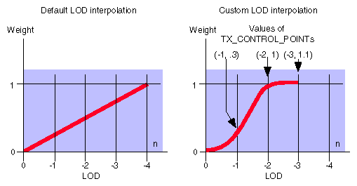
By default, OpenGL performs linear interpolation between LOD 0 and LOD -2 when a pixel's LOD is between 0 and -2. Linear interpolation between more than one LOD can result in aliasing. To minimize aliasing between the known LODs, OpenGL lets you specify a nonlinear LOD interpolation function.
Figure 7-3 shows the default linear interpolation curve and a nonlinear interpolation curve that minimizes aliasing when interpolating between two LODs.
The basic strategy is to use very little of the detail texture until the LOD is within one LOD of the maximum-detail texture. More of the information from the detail texture can be used as the LOD approaches LOD -2. At LOD -2, the full amount of detail is used, and the resultant texture exactly matches the high-resolution texture.
Use glDetailTexFuncSGIS() to specify control points for shaping the LOD interpolation function. Each control point contains a pair of values; the first value specifies the LOD, and the second value specifies the weight for that magnification level. Note that the LOD values are negative.
The following control points can be used to create a nonlinear interpolation function (as shown above in Figure 7-3):
GLfloat points[] = {
     0.0, 0.0,
    -1.0, 0.3,
    -2.0, 1.0,
    -3.0, 1.1
};
glDetailTexFuncSGIS(GL_TEXTURE_2D, 4, points);
|
Note that how these control points determine a function is system dependent. For example, your system may choose to create a piecewise linear function, a piecewise quadratic function, or a cubic function. However, regardless of which kind of function is chosen, the function passes through the control points.
If you are using texture objects, the base texture and the detail texture are separate texture objects. You can bind any base texture object to GL_TEXTURE_2D and any detail texture object to GL_DETAIL_TEXTURE_2D_SGIS. (You cannot bind a detail texture object to GL_TEXTURE_2D.)
Each base texture object contains its own detail mode, magnification filter, and LOD interpolation function. Setting these parameters therefore affects only the texture object that is currently bound to GL_TEXTURE_2D. (If you set these parameters on the detail texture object, they are ignored.)
Example 7-2 is a code fragment taken from a simple detail texture example program. The complete example is included in the source tree as detail.c. It is also available through the developer toolbox under the same name. For information on toolbox access, see http://www.sgi.com/Technology/toolbox.html.
unsigned int tex[128][128];
unsigned int detailtex[256][256];

static void
make_textures(void) {
    int i, j;
    unsigned int *p;

    /* base texture is solid gray */
    p = &tex[0][0];
    for (i=0; i<128*128; i++) *p++ = 0x808080ff;

    /* detail texture is a yellow grid over a gray background */
    /* this artificial detail texture is just a simple example */
    /* you should derive a real detail texture from the original */
    /* image as explained in the text. */
    p = &detailtex[0][0];
    for (i=0; i<256; i++) {
        for (j=0; j<256; j++) {
            if (i%8 == 0 || j%8 == 0) {
                *p++ = 0xffff00ff;
            } else {
                *p++ = 0x808080ff;
            }
        }
    }
}

static void
init(void) {
    make_textures();

    glEnable(GL_TEXTURE_2D);
    glMatrixMode(GL_PROJECTION);
    gluPerspective(90.0, 1.0, 0.3, 10.0 );
    glMatrixMode(GL_MODELVIEW);
    glTranslatef(0.,0.,-1.5);

    glClearColor(0.0, 0.0, 0.0, 1.0);
    glPixelStorei(GL_UNPACK_ALIGNMENT, 1);
    glTexEnvf(GL_TEXTURE_ENV, GL_TEXTURE_ENV_MODE, GL_MODULATE);

    /* NOTE: parameters are applied to base texture, not the detail */
    glTexParameteri(GL_TEXTURE_2D, GL_TEXTURE_MIN_FILTER, GL_LINEAR);
    glTexParameteri(GL_TEXTURE_2D, GL_TEXTURE_MAG_FILTER,
                    GL_LINEAR_DETAIL_SGIS);
    glTexParameteri(GL_TEXTURE_2D, GL_DETAIL_TEXTURE_LEVEL_SGIS, -1);
    glTexImage2D(GL_TEXTURE_2D,
                 0, 4, 128, 128, 0, GL_RGBA, GL_UNSIGNED_BYTE, tex);
    glTexImage2D(GL_DETAIL_TEXTURE_2D_SGIS,
                 0, 4, 256, 256, 0, GL_RGBA, GL_UNSIGNED_BYTE,
                 detailtex);
}

static void
draw_scene(void) {
    glClear(GL_COLOR_BUFFER_BIT);
    glBegin(GL_TRIANGLE_STRIP);
        glTexCoord2f( 0, 0); glVertex3f(-1,-0.4, 1);
        glTexCoord2f( 0, 1); glVertex3f(-1,-0.4,-1);
        glTexCoord2f( 1, 0); glVertex3f( 1,-0.4, 1);
        glTexCoord2f( 1, 1); glVertex3f( 1,-0.4,-1);
    glEnd();
    glFlush();
}
|
The filter4 parameters extension, SGIS_filter4_parameters, provides a convenience function that facilitates generation of values needed by the Texture Filter4 extension (see “SGIS_texture_filter4—The Texture Filter4 Extensions”).
| Note: This extension is part of GLU. |
Applications can derive 4 x 4 and 4 x 4 x 4 interpolation coefficients by calculating the cross product of coefficients in 2D or 3D, using the two-pixel-wide span of filter function.
The coefficients are computed in one of two ways:
Using the Mitchell-Netravali scheme. In that case, many of the desired characteristics of other 4x1 interpolation schemes can be accomplished by setting B and C in their piecewise cubic formula. Notably, the blurriness or sharpness of the resulting image can be adjusted with B and C. See Mitchell, Don. and Netravali, Arun, “Reconstruction Filters for Computer Graphics,” SIGGRAPH '88, pp. 221-228.
Using Lagrange interpolation. In that case, four piecewise cubic polynomials (two redundant ones) are used to produce coefficients resulting in images at a high sharpness level. See Dahlquist and Bjorck, “Numerical Methods”, Prentice-Hall, 1974, pp 284-285.
To choose one of the two schemas, set the filtertype parameter of gluTexFilterFuncSGI() to GLU_LAGRANGIAN_SGI or GLU_MITCHELL_NETRAVALI_SGI.
Applications use the Filter4 Parameter extension in conjunction with the Texture Filter4 extension to generate coefficients that are then used as the weights parameter of glTexFilterFuncSGIS().
To generate the coefficients, call gluTexFilterFuncSGI() with the following argument values:
target set to GL_TEXTURE_1D or GL_TEXTURE_2D
filterype set to GLU_LAGRANGIAN_SGI or GLU_MITCHELL_NETRAVALI_SGI
params set to the value appropriate for the chosen filtertype:
If filtertype is GLU_LAGRANGIAN_SGI, parms must be NULL.
If filtertype is GLU_MITCHELL_NETRAVALI_SGI, parms may point to a vector of two floats containing B and C control values or parms may be NULL in which case both B and C default to 0.5.
n set to a power of two plus one and must be less than or equal to 1025.
weights pointing an array of n floating-point values generated by the function. It must point to n values of type GL_FLOAT worth of memory.
Note that gluTexFilterFuncSGI() and glTexFilterFuncSGI() only customize filter4 filtering behavior; texture filter4 functionality needs to be enabled by calling glTexParameter*() with pname set to TEXTURE_MIN_FILTER or TEXTURE_MAG_FILTER, and params set to GL_FILTER4_SGIS. See “Using the Texture Filter4 Extension” for more information.
The point or line texgen extension, SGIS_point_line_texgen, adds two texture coordinate generation modes, which both generate a texture coordinate based on the minimum distance from a vertex to a specified line.
The section “Automatic Texture-Coordinate Generation” in Chapter 9, “Texture Mapping” of the OpenGL Programming Guide, Second Edition, discusses how applications can use glTexGen() to have OpenGL automatically generate texture coordinates.
This extension adds two modes to the existing three. The two new modes are different from the other three. To use them, the application uses one of the newly defined constants for the pname parameter and another, matching one for the param (or params) parameter. For example:
glTexGeni(GL_S, GL_EYE_POINT_SGIS, EYE_DISTANCE_TO_POINT_SGIS) |
This section discusses the sharpen texture extension, SGIS_sharpen_texture. This extension and the detail texture extension (see “SGIS_detail_texture—The Detail Texture Extension”) are useful in situations where you want to maintain good image quality when a texture must be magnified for close-up views.
When a textured surface is viewed close up, the magnification of the texture can cause blurring. One way to reduce blurring is to use a higher-resolution texture for the close-up view, at the cost of extra storage. The sharpen texture extension offers a way to keep the image crisp without increasing texture storage requirements.
Sharpen texture works best when the high-frequency information in the texture image comes from sharp edges, for example:
In a stop sign, the edges of the letters have distinct outlines, and bilinear magnification normally causes the letters to blur. Sharpen texture keeps the edges crisp.
In a tree texture, the alpha values are high inside the outline of the tree and low outside the outline (where the background shows through). Bilinear magnification normally causes the outline of the tree to blur. Sharpen texture, applied to the alpha component, keeps the outline crisp.
Sharpen texture works by extrapolating from mipmap levels 1 and 0 to create a magnified image that has sharper features than either level.
This section first explains how to use the sharpen texture extension to sharpen the component of your choice. It then gives some background information about how the extension works and explains how you can customize the LOD extrapolation function.
You can use the extension to sharpen the alpha component, the color components, or both, depending on the magnification filter. To specify sharpening, use one of the magnification filters in Table 7-6.
Table 7-6. Magnification Filters for Sharpen Texture
GL_TEXTURE_MAG_FILTER | Alpha | Red, Green, Blue |
|---|---|---|
sharpen | sharpen | |
bilinear | sharpen | |
sharpen | bilinear |
For example, suppose that a texture contains a picture of a tree in the color components, and the opacity in the alpha component. To sharpen the outline of the tree, use
glTexParameteri(GL_TEXTURE_2D, GL_TEXTURE_MAG_FILTER,
                               GL_LINEAR_SHARPEN_ALPHA_SGIS);
|
When OpenGL applies a texture to a pixel, it computes a level of detail (LOD) factor that represents the amount by which the base texture (that is, level 0) must be scaled. LOD n represents a scaling of 2-n. For example, if OpenGL needs to magnify the base texture by a factor of 4 in both S and T, the LOD is -2. Note that magnification corresponds to negative values of LOD.
To produce a sharpened texel at level-of-detail n, OpenGL adds the weighted difference between the texel at LOD 0 and LOD 1 to LOD 0; that is:
LODn = LOD0 + weight(n) * (LOD0 - LOD1) |
The variables are defined as follows:
| n | Level-of-detail | |
| weight(n) | LOD extrapolation function | |
| LOD0 | Base texture value | |
| LOD1 | Texture value at mipmap level 1 |
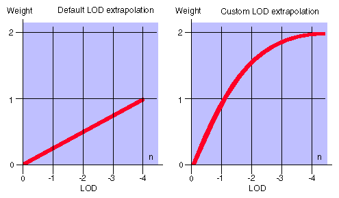
By default, OpenGL uses a linear extrapolation function, where weight(n) = -n/4. You can customize the LOD extrapolation function by specifying its control points, as discussed in the next section.
With the default linear LOD extrapolation function, the weight may be too large at high levels of magnification, that is, as n becomes more negative. This can result in so much extrapolation that noticeable bands appear around edge features, an artifact known as “ringing.” In this case, it is useful to create a nonlinear LOD extrapolation function.
Figure 7-4 shows LOD extrapolation curves as a function of magnification factors. The curve on the left is the default linear extrapolation, where weight(n) = -n/4. The curve on the right is a nonlinear extrapolation, where the LOD extrapolation function is modified to control the amount of sharpening so that less sharpening is applied as the magnification factor increases. The function is defined for n less than or equal to 0.
Use glSharpenTexFuncSGIS() to specify control points for shaping the LOD extrapolation function. Each control point contains a pair of values; the first value specifies the LOD, and the second value specifies a weight multiplier for that magnification level. (Remember that the LOD values are negative.)
For example, to gradually ease the sharpening effect, use a nonlinear LOD extrapolation curve—as shown on the right in Figure 7-4—with these control points:
GLfloat points[] = {
     0., 0.,
    -1., 1.,
    -2., 1.7,
    -4., 2.
};
glSharpenTexFuncSGIS(GL_TEXTURE_2D, 4, points);
|
Note that how these control points determine the function is system dependent. For example, your system may choose to create a piecewise linear function, a piecewise quadratic function, or a cubic function. However, regardless of the kind of function you choose, the function will pass through the control points.
Example 7-3 illustrates the use of sharpen texture. Because of space limitations, the sections dealing with X Window System setup and some of the keyboard input are omitted. The complete example is included in the source tree as sharpen.c. It is also available through the developer toolbox under the same name. See http://www.sgi.com/Technology/toolbox.html for information on toolbox access.
/* tree texture: high alpha in foreground, zero alpha in background */
#define B 0x00000000
#define F 0xA0A0A0ff
unsigned int tex[] = {
    B,B,B,B,B,B,B,B,B,B,B,B,B,B,B,B,
    B,B,B,B,B,B,B,F,F,B,B,B,B,B,B,B,
    B,B,B,B,B,B,B,F,F,B,B,B,B,B,B,B,
    B,B,B,B,B,B,F,F,F,F,B,B,B,B,B,B,
    B,B,B,B,B,B,F,F,F,F,B,B,B,B,B,B,
    B,B,B,B,B,F,F,F,F,F,F,B,B,B,B,B,
    B,B,B,B,B,F,F,F,F,F,F,B,B,B,B,B,
    B,B,B,B,F,F,F,F,F,F,F,F,B,B,B,B,
    B,B,B,B,F,F,F,F,F,F,F,F,B,B,B,B,
    B,B,B,F,F,F,F,F,F,F,F,F,F,B,B,B,
    B,B,B,F,F,F,F,F,F,F,F,F,F,B,B,B,
    B,B,F,F,F,F,F,F,F,F,F,F,F,F,B,B,
    B,B,F,F,F,F,F,F,F,F,F,F,F,F,B,B,
    B,B,B,B,B,B,F,F,F,F,B,B,B,B,B,B,
    B,B,B,B,B,B,F,F,F,F,B,B,B,B,B,B,
    B,B,B,B,B,B,B,B,B,B,B,B,B,B,B,B,
};

static void
init(void) {
    glEnable(GL_TEXTURE_2D);
    glMatrixMode(GL_PROJECTION);
    gluPerspective(60.0, 1.0, 1.0, 10.0 );
    glMatrixMode(GL_MODELVIEW);
    glTranslatef(0.,0.,-2.5);

    glColor4f(0,0,0,1);
    glClearColor(0.0, 0.0, 0.0, 1.0);
    glPixelStorei(GL_UNPACK_ALIGNMENT, 1);
    glTexEnvf(GL_TEXTURE_ENV, GL_TEXTURE_ENV_MODE, GL_DECAL);
    glTexParameteri(GL_TEXTURE_2D, GL_TEXTURE_MIN_FILTER, GL_LINEAR);
    /* sharpening just alpha keeps the tree outline crisp */
    glTexParameterf(GL_TEXTURE_2D, GL_TEXTURE_MAG_FILTER,
                    GL_LINEAR_SHARPEN_ALPHA_SGIS);
    /* generate mipmaps; levels 0 and 1 are needed for sharpening */
    gluBuild2DMipmaps(GL_TEXTURE_2D, 4, 16, 16, GL_RGBA,
                      GL_UNSIGNED_BYTE, tex);
}

static void
draw_scene(void) {
    glClear(GL_COLOR_BUFFER_BIT);
    glBegin(GL_TRIANGLE_STRIP);
        glTexCoord2f( 0, 1); glVertex2f(-1,-1);
        glTexCoord2f( 0, 0); glVertex2f(-1, 1);
        glTexCoord2f( 1, 1); glVertex2f( 1,-1);
        glTexCoord2f( 1, 0); glVertex2f( 1, 1);
    glEnd();
    glFlush();
}
|
The 4D texture extension, SGIS_texture4D, defines four-dimensional texture mapping. Four-dimensional textures are used primarily as color lookup tables for color conversion.
| Note: This extension is currently implemented only on Indigo2 IMPACT and OCTANE systems. Because of that, developers are encouraged to consult information available through the OpenGL home page, most notably the extension specifications. |
This section first provides some background information on texture clamping. It then looks at reasons for using the texture clamping extensions and explains how to use them. The two extensions are
Texture clamping is especially useful for nonrepeating textures.
OpenGL provides clamping of texture coordinates: Any values greater than 1.0 are set to 1.0, any values less than 0.0 are set to 0.0. Clamping is useful for applications that want to map a single copy of the texture onto a large surface. Clamping is discussed in detail in the section “Repeating and Clamping Textures” on page 360 of the OpenGL Programming Guide, Second Edition.
When a texture coordinate is clamped using the default OpenGL algorithm, and a GL_LINEAR filter or one of the LINEAR mipmap filters is used, the texture sampling filter straddles the edge of the texture image, taking half its sample values from within the texture image and the other half from the texture border.
It is sometimes desirable to alter the default behavior of OpenGL texture clamping operations as follows:
Clamp a texture without requiring a border or a constant border color. This is possible with the texture clamping algorithm provided by the texture edge-clamp extension. GL_CLAMP_TO_EDGE_SGIS clamps texture coordinates at all mipmap levels such that the texture filter never samples a border texel.
When used with a GL_NEAREST or a GL_LINEAR filter, the color returned when clamping is derived only from texels at the edge of the texture image.
Clamp a texture to the border color, rather than to an average of the border and edge colors. This is possible with the texture border-clamp extension. GL_CLAMP_TO_BORDER_SGIS clamps texture coordinates at all mipmap levels.
GL_NEAREST and GL_LINEAR filters return the color of the border texels when the texture coordinates are clamped.
This mode is well-suited for using projective textures such as spotlights.
Both clamping extensions are supported for one-, two-, and three-dimensional textures. Clamping always occurs for texture coordinates less than zero and greater than 1.0.
To specify texture clamping, call glTexParameteri():
Set target to GL_TEXTURE_1D, GL_TEXTURE_2D, or GL_TEXTURE_3D_EXT.
Set pname to GL_TEXTURE_WRAP_S, GL_TEXTURE_WRAP_T, or GL_TEXTURE_WRAP_R_EXT.
Set param to
GL_CLAMP_TO_EDGE_SGIS for edge clamping
GL_CLAMP_TO_BORDER_SGIS for border clamping
The texture filter4 extension, SGIS_texture_filter4, allows applications to filter 1D and 2D textures using an application-defined filter. The filter has to be symmetric and separable and have four samples per dimension. In the most common 2D case, the filter is bicubic. This filtering can yield better-quality images than mipmapping, and is often used in image processing applications.
The OpenGL Programming Guide, Second Edition, discusses texture filtering in the section “Filtering” on page 345, as follows: “Texture maps are square or rectangular, but after being mapped to a polygon or surface and transformed into screen coordinates, the individual texels of a texture rarely correspond to individual pixels of the final screen image. Depending on the transformation used and the texture mapping applied, a single pixel on the screen can correspond to anything from a small portion of a texel (magnification) to a large collection of texels (minification).”
Several filters are already part of OpenGL; the extension allows you to define your own custom filter. The custom filter cannot be a mipmapped filter and must be symmetric and separable (in the 2D case).
To use Filter4 filtering, you have to first define the filter function. Filter4 uses an application-defined array of weights (see “Determining the weights Array”). There is an implementation-dependent default set of weights.
Applications specify the filter function by calling glTexFilterFuncSGIS() (see also the glTexFilterFuncSGIS reference page) with
target set to GL_TEXTURE_1D or GL_TEXTURE_2D
filter set to GL_FILTER4_SGIS
weights pointing to an array of n floating-point values. The value n must equal 2**m + 1 for some nonnegative integer value of m.
The weights array contains samples of the filter function
f(x), 0<=x<=2 |
Each element weights[i] is the value of
f((2*i)/(n-1)), 0<=i<=n-1 |
OpenGL stores and uses the filter function as a set of samples
f((2*i)/(Size-1)), 0<=i<=Size-1 |
where Size is the implementation-dependent constant GL_TEXTURE_FILTER4_SIZE. If n equals Size, the array weights is stored directly in OpenGL state. Otherwise, an implementation-dependent resampling method is used to compute the stored samples.
| Note: “SGIS_filter4_parameters—The Filter4 Parameters Extension” provides interpolation coefficients just as they are required for GL_FILTER4_SGIS filtering. |
Size must equal 2**m + 1 for some integer value of m greater than or equal to 4. The value Size for texture target is returned by params when glGetTexParameteriv() or glGetTexParameterfv() is called with pname set to TEXTURE_FILTER4_SIZE_SGIS.
After the filter function has been defined, call glTexParameter*() with
pname set to one of GL_TEXTURE_MIN_FILTER or GL_TEXTURE_MAG_FILTER
param or params set to FILTER4_SGIS
the value of param(s) set to the function you just defined
Because filter4 filtering is defined only for non-mipmapped textures, there is no difference between its definition for minification and magnification.
The texture LOD extension, SGIS_texture_lod, imposes constraints on the texture LOD parameter. Together these constraints allow a large texture to be loaded and used initially at low resolution, and to have its resolution raised gradually as more resolution is desired or available. By providing separate, continuous clamping of the LOD parameter, the extension makes it possible to avoid “popping” artifacts when higher-resolution images are provided.
To achieve this, the extension imposes the following constraints:
To understand the issues discussed in this section, you should be familiar with the issues discussed in the sections “Multiple Levels of Detail” on page 338 and “Filtering” on page 344 of the OpenGL Programming Guide.
To specify a minimum or maximum level of detail for a specific texture, call glTexParameter*() and set
LOD is clamped to the specified range before it is used in the texturing process. Whether the minification or magnification filter is used depends on the clamped LOD.
The OpenGL Specification describes a “complete” set of mipmap image arrays at levels 0 (zero) through p, where p is a well-defined function of the dimensions of the level 0 image.
This extension lets you redefine any image level as the base level (or maximum level). This is useful, for example, if your application runs under certain time constraints, and you want to make it possible for the application to load as many levels of detail as possible but stop loading and continue processing, choosing from the available levels after a certain period of time has elapsed. Availability in that case does not depend on what is explicitly specified in the program but on what could be loaded in a specified time.
To set a new base (or maximum) level, call glTexParameteri(), glTexParemeterf(), glTexParameteriv(), or glTexParameterfv() and set
target to GL_TEXTURE_1D, GL_TEXTURE_2D, or GL_TEXTURE_3D_EXT
pname to
GL_TEXTURE_BASE_LEVEL_SGIS to specify a base level
GL_TEXTURE_MAX_LEVEL_SGIS to specify a maximum level
param to (or params pointing to) the desired value
Note that the number used for the maximum level is absolute, not relative to the base level.
The texture select extension, SGIS_texture_select, allows for more efficient use of texture memory by subdividing the internal representation of a texel into one, two, or four smaller texels. The extension may also improve performance of texture loading.
On InfiniteReality graphics systems, the smallest texel supported by the hardware is 16 bits. The extension allows you to pack multiple independent textures together to efficiently fill up space in texture memory (the extension itself refers to each of the independent textures as component groups).
Two eight-bit textures can be packed together. Examples include 8-bit luminance, 8-bit intensity, 8-bit alpha, and 4-bit luminance-alpha.
Four four-bit textures can be packed together. Examples include 4-bit luminance, 4-bit intensity, and 4-bit alpha.
The extension allows developers to work with these components by providing several new texture internal formats. For example, assume that a texture internal format of GL_DUAL_LUMINANCE4_SGIS is specified. Now there are two component groups, where each group has a format of GL_LUMINANCE4. One of the two GL_LUMINANCE groups is always selected. Each component can be selected and interpreted as a GL_LUMINANCE texture.
| Note: The point of this extension is to save texture memory. Applications that need only 8-bit or 4-bit texels would otherwise use half or one quarter of texture memory. However, applications that use 16-bit or larger texels (such as RGBA4, LA8) won't benefit from this extension. |
To use the texture select extension, first call glTexImage*D() to define the texture using one of the new internal formats:
glTexImage[n]D[EXT] ( /* Definition */
     internalFormat =
         GL_DUAL_{ ALPHA, LUMINANCE, INTENSITY * }{4, 8, 12, 16 }_SGIS
         GL_DUAL_LUMINANCE_ALPHA{ 4, 8 } _SGIS
         GL_QUAD_{ ALPHA, LUMINANCE, INTENSITY*}{ 4, 8 }_SGIS
         );
|
The system then assigns parts of the texture data supplied by the application to parts of the 16-bit texel, as illustrated in Table 7-7.
To select one of the component groups for use during rendering, the application then calls glTexParameter*() as follows:
glTexParameteri ( /* Selection & Usage */
        target = GL_TEXTURE_[n]D[_EXT],
        param = GL_DUAL_TEXTURE_SELECT_SGIS GL_QUAD_TEXTURE_SELECT_SGIS
        value = { 0, 1 },
                { 0, 1, 2, 3 }
         );
|
There is always a selection defined for both DUAL_TEXTURE_SELECT_SGIS and QUAD_TEXTURE_SELECT_SGIS formats. The selection becomes active when the current texture format becomes one of the DUAL* or QUAD* formats, respectively. If the current texture format is not one of DUAL* or QUAD* formats, this extension has no effect.
Component mapping from the canonical RGBA to the new internal formats is as follows:
Table 7-7. Texture Select Host Format Components Mapping
Format | Grouping |
|---|---|
DUAL* formats that are groups of ALPHA, LUMINANCE, and INTENSITY | RED component goes to the first group ALPHA component goes to the second group |
RED and GREEN components go to the first group BLUE and ALPHA go to the second group | |
RED component goes to the first group GREEN component to the second group BLUE component to the third group ALPHA component to the fourth group |
The interpretation of the bit resolutions of the new internal formats is implementation dependent. To query the actual resolution that is granted, call glGetTexLevelParameter() with pname set appropriately, for example GL_TEXTURE_LUMINANCE_SIZE. The bit resolution of similar type components in a group, such as multiple LUMINANCE components, is always the same.
The clipmap extension, SGIX_clipmap, allows applications to use dynamic texture representations that efficiently cache textures of arbitrarily large size in a finite amount of physical texture memory. Only those parts of the mipmapped texture that are visible from a given application-specified location are stored in system and texture memory. As a result, applications can display textures too large to fit in texture memory by loading parts on the texture into texture memory only when they are required.
Full clipmap support is implemented in IRIS Performer 2.2 (or later). Applications can also use this extension on the appropriate hardware (currently InfiniteReality only) for the same results. In that case, the application has to perform memory management and texture loading explicitly.
This section explains how clipmaps work and how to use them in the following sections:
“Clipmap Overview” explains the basic assumptions behind clipmaps.
“Using Clipmaps From OpenGL” provides step by step instructions for setting up a clipmap stack and for using clipmaps. Emphasis is on the steps, with references to the background information as needed.
“Clipmap Background Information” explains some of the concepts behind the steps in clipmap creation in more detail.
“Virtual Clipmaps” discusses how to work with a virtualized clipmap, which is the appropriate solution if not all levels of the clipmap fit.
| Note: For additional conceptual information, see the specification for the clipmap extension, which is available through the developer's toolbox. |
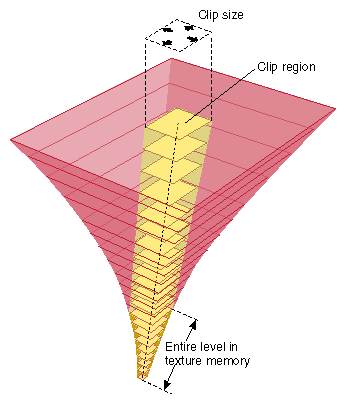
Clipmaps avoid the size limitations of normal mipmaps by clipping the size of each level of a mipmap texture to a fixed area, called the clip region (see Figure 7-5). A mipmap contains a range of levels, each four times the size of the previous one. Each level (size) determines whether clipping occurs:
For levels smaller than the clip region—that is, for low-resolution levels that have relatively few texels—the entire level is kept in texture memory.
Levels larger than the clip region are clipped to the clip region's size. The clip region is set by the application, trading off texture memory consumption against image quality. (The image may become blurry because texture accesses outside the clip region are forced to use a coarse LOD.)
The clipmap algorithm is based on the following constraints:
The viewer can see only a small part of a large texture from any given viewpoint.
The viewer looks at a texture from only one location.
The viewer moves smoothly relative to the clipmap geometry (no teleporting).
The textured geometry must have a reasonable, relatively flat topology.
Given these constraints, applications can maintain a high-resolution texture by keeping only those parts of the texture closest to the viewer in texture memory. The remainder of the texture is on disk and cached in system memory.
The clipmap constraints work because only the textured geometry closest to the viewer needs a high-resolution texture. Distant objects are smaller on the screen, so the texels used on that object also appear smaller (cover a small screen area). In normal mipmapping, coarser mipmap levels are chosen as the texel size gets smaller relative to the pixel size. These coarser levels contain fewer texels because each texel covers a larger area on the textured geometry.
Clipmaps store only part of each large (high-resolution) mipmap level in texture memory. When the user looks over the geometry, the mipmap algorithm starts choosing texels from a lower level before running out of texels on the clipped level. Because coarser levels have texels that cover a larger area, at a great enough distance, texels from the unclipped, smaller levels are chosen as appropriate.
When a clip size is chosen, the mipmap levels are separated into two categories:
The nonclipped levels are viewpoint independent; each nonclipped texture level is complete. Clipped levels, however, must be updated as the viewer moves relative to the textured geometry.
Clipmaps are not completely interchangeable with regular OpenGL textures. Here are some differences:
Centering. In a regular texture, every level is complete in a regular texture. Clipmaps have clipped levels, where only the portion of the level near the clipmap center is complete. In order to look correct, a clipmap center must be updated as the viewport of the textured geometry moves relative to the clipmap geometry.
As a result, clipmaps require functionality that recalculates the center position whenever the viewer moves (essentially each frame). This means that the application has to update the location of the clip center as necessary.
Texel Data. A regular texture is usually only loaded once, when the texture is created. The texel data of a clipmap must be updated by the application each time the clipmap center is moved. This is usually done by calling glTexSubImage2D() and using the toroidal loading technique (see “Toroidal Loading”).
To use clipmaps, an application has to take care of two distinct tasks, discussed in this section:
To set up the clipmap stack, an application has to follow these steps:
Call glTexParameter*() with the GL_TEXTURE_MIN_FILTER_SGIX parameter set to GL_LINEAR_CLIPMAP_LINEAR_SGIX to let OpenGL know that clipmaps, not mipmaps will be used.
glTexParameteri(GL_TEXTURE_2D, GL_TEXTURE_MIN_FILTER,
               GL_LINEAR_CLIPMAP_LINEAR);
GL_TEXTURE_MAG_FILTER can be anything but GL_FILTER4_SGIS
Set the GL_TEXTURE_CLIPMAP_FRAME_SGIX parameter to set an invalid border region of at least eight pixels.
The frame is the part of the clip that the hardware should ignore. Using the frame avoids certain sampling problems; in addition, the application can load into the Frame region while updating the texture. See “Invalid Borders” for more information.
In the following code fragment, size is the fraction of the clip size that should be part of the border; that is, .2 would mean 20 percent of the entire clip size area would be dedicated to the invalid border, along the edge of the square clip size region.
GLfloat size = .2f;      /* 20% */
/* can range from 0 (no border) to 1 (all border) */
glTexParameterf(GL_TEXTURE_2D,GL_TEXTURE_CLIPMAP_FRAME_SGIX,size);
Set GL_TEXTURE_CLIPMAP_CENTER_SGIX to set the center texel of the highest-resolution texture, specified as an integer. The clip center is specified in terms of the top (highest-resolution) level of the clipmap, level 0. OpenGL automatically adjusts and applies the parameters to all of the other levels.
The position of the center is specified in texel coordinates. Texel coordinate are calculated by taking the texture coordinates (which range from 0 to 1 over the texture) and multiplying them by the size of the clipmap's top level. See “Moving the Clip Center” for more information.
The following code fragment specifies the location of the region of interest on every clipped level of clipmap. The location is specified in texel coordinates, so texture coordinates must be multiplied by the size of the top level in each dimension. In this example, center is at the center of texture (.5, .5). Assume this clipmap is 4096 (s direction) by 8192 (t direction) at level 0.
		int center[3];
		center[0] = .5 * 4096;
		center[1] = .5 * 8192;
		center[2] = 0; /* always zero until 3d clipmaps supported */

		glTexParameteriv(GL_TEXTURE_2D, GL_TEXTURE_CLIPMAP_CENTER_SGIX,center);
Set GL_TEXTURE_CLIPMAP_OFFSET_SGIX to specify the offset. The offset parameter allows applications to offset the origin of the texture coordinates so that the incrementally updated texture appears whole and contiguous.
Like the center, the offset is supplied in texel coordinates. In the code fragment below, clip size is the size of the region of interest.
		int offset[2];

		offset[0] = (center[0] + clipsize/2) % clipsize;
		offset[1] = (center[1] + clipsize/2) % clipsize;

		glTexParameteriv(GL_TEXTURE_2D,
				 GL_TEXTURE_CLIPMAP_OFFSET_SGIX,
				 offset);
Call glTexImage2D() to define the highest-resolution level that contains the entire map. This indirectly tells OpenGL what the clip size is and which level of the clipmap contains the largest clipped level. OpenGL indirectly calculates the clip size of a clipmap by the size of the texture levels. Although the clipmap levels can be loaded in any order, it is most efficient for the current clipmap system if the top of the pyramid is loaded first. Note that a clipmap's clip size level is at some level other than zero (otherwise there would be no levels larger than the clip size; that is, no clipped levels.)
In the following code fragment, the clipmap is RGB, with a top level of dimensions 8192 by 8192, and a clip size of 512 by 512. There will be 12 levels total, and the last level at which the whole mipmap is in memory (512 level) is level 4.
GLint pyramid_level, border = 0;
GLsizei clipsize_wid, clipsize_ht;
	clipsize_wid = clipsize_ht = 512;
pyramid_level = 4; /* 8192 = 0, 4096 = 1, 2048 = 2, 1024 = 3, ... */

		glTexImage2D(GL_TEXTURE_2D,
			     pyramid_level,
			     GL_RGB, /* internal format */
			     clipsize_wid,
			     clipsize_ht,
			     border, /* not invalid border! */,
			     GL_RGB, /* format of data being loaded */
			     GL_BYTE, /* type of data being loaded */
			     data); /* data can be null and subloaded later if desired */
Create the clipmap stack by calling glTexImage2D() repeatedly for each level.
If you want to use a virtual clipmap, you can use the texture_LOD extension (see “SGIS_texture_lod—The Texture LOD Extension”) to specify the minimum and maximum LOD. See “Virtual Clipmaps”.
After the application has precomputed all mipmaps, it stores them on disk for easy access. Note that it is not usually possible to create the stack in real time.
As the user moves through the “world,” the center of the clipmap usually changes with each frame. Applications therefore have to update the clipmap stack with each frame, following these steps:
Compute the difference between the old and new center.
See “Moving the Clip Center” for background information.
Determine the incremental texture load operations needed for each level.
Perform toroidal loads by calling glTexSubImage2D() to load the appropriate texel regions.
“Toroidal Loading” discusses this in more detail.
Set the parameters for center and offset for the next move.
The following sections provide background information for the steps in “Using Clipmaps From OpenGL”.
Only a small part of each clipped level of a clipmap actually resides in texture memory. As a result, moving the clip center requires updating the contents of texture memory so it contains the pixel data corresponding to the new location of the region of interest.
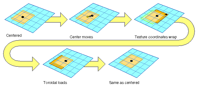
Updates must usually happen every frame, as shown in Figure 7-6. Applications can update the clipmaps to the new center using toroidal loading (see “Toroidal Loading”).
The clip center is set by the application for level 0, the level with the highest resolution. The clipmap code has to derive the clip center location on all levels. As the viewer roams over a clipmap, the centers of each mipmap level move at a different rate. For example, moving the clip center one unit corresponds to the center moving one half that distance in each dimension in the next-coarser mipmap level.
When applications use clipmaps, most of the work consists of updating the center properly and updating the texture data in the clipped levels reliably and efficiently for each frame.To facilitate loading only portions of the texture at a time, the texture data should first be subdivided into a contiguous set of rectangular areas, called tiles. These tiles can then be loaded individually from disk into texture memory.
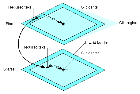
Applications can improve performance by imposing alignment requirements to the regions being downloaded to texture memory. Clipmaps support the concept of an invalid border to provide this feature. The border is an area around the perimeter of a clip region that is guaranteed not to be displayed. The invalid border shrinks the usable area of the clip region, and can be used to dynamically change the effective size of the clip region.
When texturing requires texels from a portion of an invalid border at a given mipmap level, the texturing system moves down a level, and tries again. It keeps going down to coarser levels until it finds texels at the proper coordinates that are not in the invalid region. This is always guaranteed to happen, because each level covers the same area with fewer texels. Even if the required texel is clipped out of every clipped level, the unclipped pyramid levels will contain it.
The invalid border forces the use of lower levels of the mipmap. As a result, it
Reduces the abrupt discontinuity between mipmap levels if the clip region is small.
Using coarser LODs blends mipmap levels over a larger textured region.
Improves performance when a texture must be roamed very quickly.
Because the invalid border can be adjusted dynamically, it can reduce the texture and system memory loading requirements at the expense of a blurrier textured image.
To minimize the bandwidth required to download texels from system to texture memory, the image cache's texture memory should be updated using toroidal loading, which means the texture wraps upon itself. (see Figure 7-6).
A toroidal load assumes that changes in the contents of the clip region are incremental, such that the update consists of
new texels that need to be loaded
texels that are no longer valid
texels that are still in the clip region, but have shifted position
Toroidal loading minimizes texture downloading by updating only the part of the texture region that needs new texels. Shifting texels that remain visible is not necessary, because the coordinates of the clip region wrap around to the opposite side.
As the center moves, only texels along the edges of the clipmap levels change. To allow for incremental loading only of these texels via glTexSubImage2D(), toroidal offset values have to be added to the texture addresses of each level. The offset is specified by the application (see “Setting Up the Clipmap Stack”). The offsets for the top level define the offsets for subsequent levels by a simple shift, just as with the center.
You can use the texture LOD extension in conjunction with mipmapping to change the base level from zero to something else. Using different base levels results in clipmaps with more levels than the hardware can store at once when texturing.
These larger mipmapped textures can be used by only accessing a subset of all available mipmap levels in texture memory at any one time. A virtual offset is used to set a virtual “level 0” in the mipmap, while the number of effective levels indicates how many levels starting from the new level 0 can be accessed. The minLOD and maxLOD are also used to ensure that only valid levels are accessed. The application typically divides the clipmapped terrain into pieces, and sets the values as each piece is traversed, using the relative position of the viewer and the terrain to calculate the values.
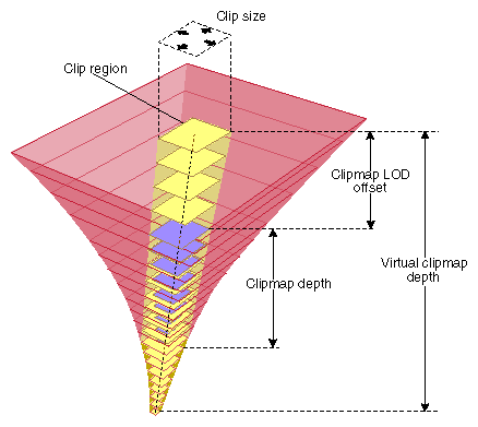
To index into a clipmap of greater than GL_MAX_CLIPMAP_DEPTH_SGIX levels of detail, additional parameters are provided to restrictively index a smaller clipmap of (N+1) levels located wholly within a complete, larger clipmap. Figure 7-8 illustrates how a virtual clipmap fits into a larger clipmap stack. The clipmap extension specification explains the requirements for the larger and smaller clipmap in more detail.
When creating a virtual clipmap, an application calls glTexParameteriv(), or glTexParameterfv() with
target set to GL_TEXTURE_2D
pname set to GL_TEXTURE_CLIPMAP_VIRTUAL_DEPTH_SGIX
params set to (D,N+1,V+1)
where D is the finest level of the clipmap, N+1 is the depth of the clipmap, and V+1 is the depth of the virtual clipmap.
If the depth of the virtual clipmap is zero, clipmap virtualization is ignored, and texturing proceeds as with a non-virtual clipmap.
If you have virtualized the clipmap, you will be adjusting the LOD offset and possibly the number of displayable levels as you render each chunk of polygons that need a different set of clipmap levels to be rendered properly. The application has to compute the levels needed.
The texture environment add extension, SGIX_texture_add_env, defines a new texture environment function, which scales the texture values by the constant texture environment color, adds a constant environment bias color, and finally adds the resulting texture value on the in-coming fragment color. The extension can be used to simulate highlights on textures (although that functionality is usually achieved with multi-pass rendering) and for situations in which it has to be possible to make the existing color darker or lighter, for example, for simulating an infrared display in a flight simulator.
OpenGL 1.1 supports four texture environment functions: GL_DECAL, GL_REPLACE, GL_MODULATE, and GL_BLEND.
The extension provides an additional environment, GL_ADD, which is supported with the following equation:
Cv = Cf + CcCt + Cb |
where
| Cr | Fragment color | |
| Cc | Constant color (set by calling glTexEnv()) with pname set to GL_TEXTURE_ENV_COLOR) | |
| Ct | Texture color | |
| Cb | Bias color (set by calling glTexEnv() with pname set to GL_TEXTURE_ENV_BIAS_SGIX.) and param set to a value greater than -1 and less than 1. |
The new function works just like the other functions discussed in the section “Texture Functions” on page 354 of the OpenGL Programming Guide, Second Edition.
The texture LOD bias extension, SGIX_texture_lod_bias, allows applications to bias the default LOD to make the resulting image sharper or more blurry. This can improve image quality if the default LOD is not appropriate for the situation in question.
If an application uses an image as a texture map, the image may have to be scaled down to a smaller size on the screen. During this process the image must be filtered to produce a high-quality result. Nearest-neighbor or linear filtering do not work well when an image is scaled down; for better results, an OpenGL program can use mipmapping. A mipmap is a series of prefiltered texture maps of decreasing resolution. Each texture map is referred to as one level of detail or LOD. Applications create a mipmap using the routines gluBuild1DMipmaps() or gluBuild2DMipmaps(). Mipmaps are discussed starting on page 338 of the OpenGL Programming Guide, Second Edition.
Graphics systems from Silicon Graphics automatically select an LOD for each textured pixel on the screen. However, in some situations the selected LOD results in an image that is too crisp or too blurry for the needs of the application. For example, 2D mipmapping works best when the shape of the texture on the screen is a square. If that is not the case, then one dimension of the texture must be scaled down more than the other to fit on the screen. By default the LOD corresponding to the larger scale factor is used, so the dimension with the smaller scale factor will appear too blurry.
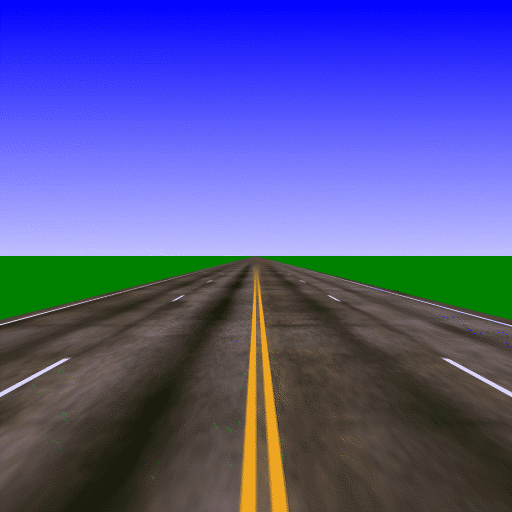
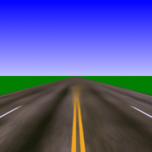
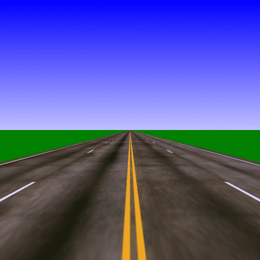
Figure 7-9 shows an image that is too blurry with the default LOD bias. You can see that the marker in the middle of the road is blurred out. In Figure 7-10, this effect is exaggerated by a positive LOD bias. Figure 7-11 shows how the markers become visible with a negative LOD bias.
As another example, the texture data supplied by the application may be slightly oversampled or undersampled, so the textured pixels drawn on the screen may be correspondingly blurry or crisp.
The texture LOD bias extension allows applications to bias the default LOD to make the resulting image sharper or more blurry. An LOD of 0 corresponds to the most-detailed texture map, an LOD of 1 corresponds to the next smaller texture map, and so on. The default bias is zero, but if the application specifies a new bias, that bias will be added to the selected LOD. A positive bias produces a blurrier image, and a negative bias produces a crisper image. A different bias can be used for each dimension of the texture to compensate for unequal sampling rates.
Examples of textures that can benefit from this LOD control include:
Images captured from a video source. Because video systems use non-square pixels, the horizontal and vertical dimensions may require different filtering.
A texture that appears blurry because it is mapped with a nonuniform scale, such as a texture for a road or runway disappearing toward the horizon (the vertical dimension must be scaled down a lot near the horizon, the horizontal dimension is not scaled down much).
Textures that don't have power of two dimensions and therefore had to be magnified before mipmapping (the magnification may have resulted in a nonuniform scale).
To make a mipmapped texture sharper or blurrier, applications can supply a negative or positive bias by calling glTexParameter*() with
You can specify a bias independently for one or more texture dimensions. The final LOD is at least as large as the maximum LOD for any dimension; that is, the texture is scaled down by the largest scale factor, even though the best scale factors for each dimension may not be equal.
Applications can also call glGetTexParameter*() to check whether one of these values has been set.
The texture_scale_bias extension, SGIX_texture_scale_bias, allows applications to perform scale, bias, and clamp operations as part of the texture pipeline. By allowing scale or bias operations on texels, applications can make better utilization of the color resolution of a particular texture internal format, by, for example, performing histogram normalization, or gamut expansion. In addition some color remapping may be performed with this extension if a texture color lookup table is not available or too expensive.
The scale, bias, and clamp operations are applied, in that order, directly before the texture environment equations, or, if the SGI_texture_color_table extension exists, directly before the texture color lookup table. The four values for scale (or bias) correspond to the R, G, B, and A scale (or bias) factors. These values are applied to the corresponding texture components, Rt, Gt, Bt, and At. Following the scale and bias is a clamp to the range [0, 1].
To use the extension, an application calls glTexParameter*() with a pname parameter GL_POST_TEXTURE_FILTER_BIAS_SGIX or GL_POST_TEXTURE_FILTER_SCALE_SGIX and with params set to an array of four values.The scale or bias values can be queried using glGetTexParameterfv() or glGetTexParameteriv(). The scale, bias, and clamp operations are effectively disabled by setting the four scale values to 1 and the four bias values to 0. There is no specific enable or disable token for this extension.
Because an implementation may have a limited range for the values of scale and bias (for example, due to hardware constraints), this range can be queried. To obtain the scale or bias range, call glGet*() with GL_POST_TEXTURE_FILTER_SCALE_RANGE_SGIX or GL_POST_TEXTURE_FILTER_BIAS_RANGE_SGIX, respectively as the value parameter. An array of two values is returned: the first is the minimum value and the second is the maximum value.
The texture multibuffer extension, SGIX_texture_multi_buffer, allows applications to change the way OpenGL handles multiple textures.
Texture objects, which were introduced in OpenGL 1.1, allow the simultaneous definition of multiple textures. As a result, you can in principle render one texture and at the same time load another texture into hardware or perform other actions on its definition. This is true as long as all redefinitions strictly follow any use of the previous definition.
Conceptually using textures in this fashion is similar to frame buffer double-buffering, except that the intent here is to provide a hint to OpenGL to promote such double-buffering if and wherever possible. The effect of such a hint is to speed up operations without affecting the result. Developers on any particular system must be knowledgable and prepared to accept any trade-offs that may result from such a hint.
The extension is currently used for video texture-mapping; that is, instead of mapping a static image onto an object in a 3D view, live video is mapped. So there is a variety of special effects that can be done. On Indigo2 IMPACT and OCTANE, the method is to use a GLX extension to set the “readsource” to be “video” and then call glCopyTexImage2D() to get the latest video image into texture memory. Using the multibuffer extension, it is possible to be drawing with the previous video frame (the front buffer) while the new frame is being loaded in (the back buffer). This really speeds things up.
To use the extension, call glHint() with the target parameter set to GL_TEXTURE_MULTI_BUFFER_HINT_SGIX.
If you specify a hint of GL_FASTEST, texture multi-buffering is used whenever possible to improve performance. Generally, textures that are adjacent in a sequence of multiple texture definitions have the greatest chance of being in different buffers. The number of buffers available at any time depends on various factors, such as the machine being used and the textures' internal formats.
