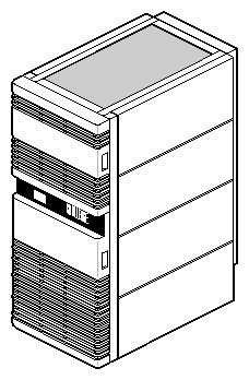
The POWER Challenge and Challenge rackmount system (model CMN A010) is a high-performance server installed in a configurable rackmounted enclosure (Figure 1-1). Hereinafter, both these systems are referred to as the Challenge system, unless otherwise specified. This guide contains information about Challenge system hardware and software, as well as information about a base set of supported peripherals.
The following is a list of the standard features of the Challenge rackmount server:
The POWERpath-2 (Everest) board set, which
supports a maximum of 36 R4400™ processors in the Challenge system (on 9 IP19 CPU boards)
supports a maximum of 18 R8000® processors in the POWER Challenge system (on 9 IP21 CPU boards)
supports a maximum of 36 R10000™ processors in the Challenge 10000 or POWER Challenge 10000 (on 9 IP25 CPU boards)
can be configured with up to eight MC3 interleaved memory boards, each having a maximum of 2 GB of memory
can be configured with a maximum of five POWERChannel 2 (IO4) interface boards, providing multiple VMEbus, network, and peripheral interfaces
Two separate cardcages, providing 15 Ebus slots, 6 VMEbus slots, and 3 Power board slots
SCSI drive enclosure (SCSIBox), supporting 8 half-height SCSI devices or 4 full-height SCSI devices, which
has dual configurable SCSI channels, compatible with both 8- and 16-bit SCSI devices
Standalone System Controller to monitor system status and to record error information in the event of a shutdown
Microprocessor-controller cooling system for quieter, more efficient operation
Following is a list of available options:
Third cardcage with 20 VMEbus slots
Additional I/O and VMEbus interfaces
Second SCSIBox 2 (identical to the standard box)
Memory upgrade using 16 MB and 64 MB SIMMs
CPU upgrades using additional microprocessor boards
Additional POWERmodules and power boards
A visualization console option providing a basic color graphics interface to the POWER Challenge system
The Challenge rackmount server places the power of the POWERpath-2 system board set in a chassis designed for maximum expansion. A unique backplane design with board connectors on both sides (referred to as a midplane) allows the system chassis to house twice the number of boards that can be supported by a conventional chassis of the same size.
The modular power supplies and distribution system ensure that the system chassis can be easily configured to meet the increasing power requirements that accompany system expansion. The internal SCSIBox 2 drive enclosures and multiple interfaces for external drives provide virtually unlimited data storage resources.
In its maximum configuration, the Challenge server can combine 41 circuit boards and 16 disk/tape/CD drives in a single cabinet. Because of the complexity that accompanies the large number of possible configurations, the basic version of the system is described first, followed by brief descriptions of the available options.
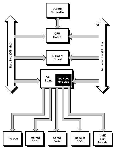
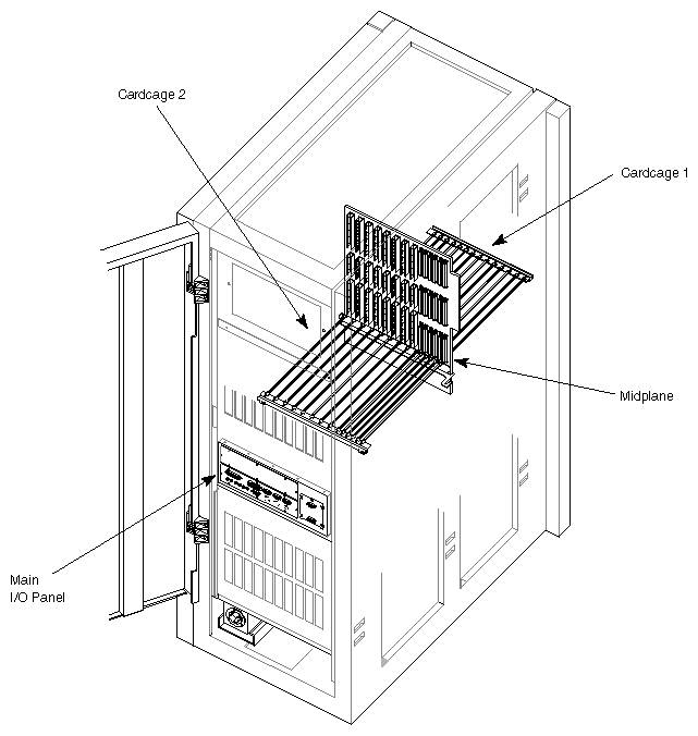
All Challenge servers are shipped with a standard set of POWERpath-2 system boards and a drive enclosure that supports eight half-height SCSI devices. Each of these system components is described in the following sections. Figure 1-2 is a functional block diagram of a basic Challenge rackmount server. Figure 1-3 illustrates the primary components of the system chassis.
| Note: The POWER Challenge does support an optional visualization console, providing a basic color graphics interface to the system. |
This section provides a brief description of the boards that compose the POWERpath-2 board set.
The CPU board is the heart of the POWERpath-2 board set. The Challenge system has an IP19 CPU board, and the POWER Challenge has the IP21 CPU board.
The IP19 (which resides in a Challenge system) is a multiprocessor CPU that is configured with either two or four R4400 processors. In its maximum configuration, the rackmount server supports nine IP19s, giving the system a total of 36 processors. The IP19 board logic is “sliced” so that each processor has its own dedicated supporting logic. This arrangement allows each processor to run independently of the others. The only board logic shared by the processors is the bus interface. A set of five ASICs (four data, one address) provides the interface between the CPUs and the system data and address buses.
The IP21 CPU (which resides in a POWER Challenge system) is also a multiprocessor CPU board and comes configured with either one or two R8000 processors. However, the IP21 delivers even more processing power and speed than the IP19 board, primarily by providing a dedicated floating point unit (FPU) chip and additional support hardware. This frees up the CPU to perform other required tasks and eliminates much of the wait states. The IP21 also implements dual-ported cache that enables two data accesses at the same time to improve processing speed significantly. In its maximum configuration, the POWER Challenge server supports up to 18 processors on nine CPU boards.
The IP25 board in your Challenge 10000 or POWER Challenge 10000 rackmount can house one, two, or four MIPS R10000 64-bit microprocessors. Your system can house up to nine IP25s with a potential system total of 36 microprocessors. The four-way superscalar R10000 microprocessor can fetch four instructions and issue up to five instructions per cycle. A superscalar processor is one that can fetch, execute and complete more than one instruction in parallel.
The MC3 interleaved memory board has 32 SIMM slots and can be populated with a combination of 16 MB and/or 64 MB SIMMs. In its maximum configuration, each board can supply 2 GB of random-access memory. The memory board supports up to eight-way interleaving, providing faster access times and allowing faulty components to be configured out of the memory map.
The POWERChannel 2 interface board (also referred to as the IO4) provides the Challenge system with all of the basic serial ports and interfaces needed for system operation. These interfaces include the serial port, a parallel port, the SCSI bus interfaces, the Flat Cable Interface (FCI), the AUI Ethernet interface, three RS-232 serial ports, and an RS-422 serial connector.
The IO4 board also provides the “base” to which a variety of interface (mezzanine) boards can be mounted.
| Note: The VMEbus Channel Adapter Module (VCAM) is the only mezzanine board installed as standard equipment on all systems. All of the other mezzanine boards are optional. |
The IO4 device controllers transfer addresses and data between the various I/O interfaces and the Ebus over the 64-bit Interface bus (Ibus). The Ibus connects to the system buses through the IA and ID ASICs, forming an asynchronous boundary that provides the Ibus with a 320 MB per second bandwidth.
The IA and ID ASICs act as bus adapters that connect the Ibus to the much faster Ebus. In addition to making the necessary conversions back and forth between the two buses, the IA and ID ASICs perform virtual address mapping for DMA operations, and maintain cache coherency between the Ebus and the I/O subsystem.
The IO4 contains two FCIs that are proprietary to Silicon Graphics®. FCIs are synchronous, point-to-point interfaces that allow communication between devices. The FCIs are used to connect the VME64 bus or FDDI adapters to the IO4 board. The two FCIs on the first (or only) IO4 board in the system are connected to the VME Channel Adapter Module (VCAM) board.
| Note: FCIs can operate at up to 200 MB per second for VMEbus adapters. |
The VCAM provides the interface between the VMEbus and the system buses. It is mounted on the first IO4 board, and the pair are installed in the system midplane as a unit.
The VMEbus interface supports all protocols defined in Revision C of the VME™ Specification, plus the A64 and D64 modes defined in Revision D. The D64 mode allows DMA bandwidths of up to 60 MB per second. The VMEbus interface can operate as either a master or a slave. It supports DMA-to-memory transfers on the Ebus, as well as programmed I/O operations from the Ebus to addresses on the VMEbus.
The VMEbus is supported through a VCAM interface (GCAM with the visualization console option) connected to an IO4 board. This bus is standard equipment and is located in the main backplane, next to the Ebus. The VCAM or optional GCAM plugs directly into the IO4 board without any cabling. With the optional visualization console the GCAM covers one of the available mezzanine connectors on the standard I04.
The IO4 board contains two 16-bit SCSI-3 disk controllers. Each controller can operate with a bandwidth of up to 20 MB per second and can be configured for either single-ended or differential SCSI channels.
The IO4's Ethernet Interface operates at the standard Ethernet 10 MB per second rate and supports AUI (15-pin) physical connections. The controller is intelligent and requires no direct CPU involvement when packets are transmitted or received.
The IO4 contains a DMA-driven parallel port capable of operating printers, or performing high-speed data transfer to or from external equipment at rates of up to 300 KB per second.
The IO4 board also supports three RS-232 and one RS-422 serial ports, all of which are capable of asynchronous operation at rates up to 19.2 Kbaud. The RS-422 port may be operated at 38.4 Kbaud, provided the RS-232 ports are not all in use.
To accommodate extra disk controllers, the SCSI mezzanine board (S mezz) contains three 16-bit SCSI-3 controllers. Two of the controllers are differential only; the third is configurable as single-ended or differential. These controllers are identical to those used on the main IO4 board. S mezz boards can be plugged into either or both of the mezzanine card slots on an IO4 board, allowing up to eight SCSI-3 controllers per IO4 board.
The Challenge rackmount system midplane has a combination of 15 POWERpath-2 (Ebus) connectors, six 9U VMEbus connectors, and three power board connectors. In addition to the midplane, an optional 20-slot VMEbus backplane is available. See Chapter 2, “Touring the Chassis,” for more information and the locations of the midplane and backplane.
SCSI devices are the only data storage devices internally supported by the Challenge system. The standard configuration is a single SCSIBox 2 that houses a maximum of 8 half-height SCSI devices. These devices include 1.2 GB and 2 GB disk drives; 1/4-inch, 4 mm DAT and 8 mm tape drives; and CD-ROM players.
All drives must be configured as Front Loading Devices (FLDs) before they can be mounted in the drive enclosure. An FLD is a SCSI storage device mounted on a P8 “drive sled.” The drive sled adapts the drive's power and signal connectors to the connectors within the SCSIBox. Drives configured in this manner require no cabling; receptacles at the rear of the sled assemblies automatically engage the corresponding connectors on the drive box's backplane when the drive is installed. A second, identical drive enclosure is available as an option. Both SCSIBoxes have a pair of independent, configurable SCSI channels.
Though the system supports only SCSI devices internally, other drive types with a VMEbus-compatible controller board and IRIX-compatible device drivers can be supported remotely.
| Note: Non-SCSI devices can be supported, but cannot be used as the boot device. |
The System Controller is a microprocessor with battery-backed memory that manages the system power-on sequence, as well as a portion of the boot process. During normal system operation, the System Controller monitors various system operating parameters such as fan speed, chassis temperature, the system clock, and backplane voltages. If the monitored operating parameters move out of their predetermined ranges, the System Controller can shut down the system. Error messages are stored in a log; therefore, you can retrieve messages in the event of a system shutdown.
A 128-character display is visible through a cutout in the system chassis' upper front door. This display gives you information about system status and detailed error messages in the event of a failure.
Four function buttons allow you to move through the menus and displays and to execute the controller functions. See Chapter 5, “Having Trouble?,” for a detailed explanation of the System Controller features.
POWER Challenge systems using the visualization console option have a Graphics Channel Adapter Module (GCAM) board. The GCAM contains a VME adapter subsystem and interfaces to the optional visualization console graphics board in the fifth VME slot. A flat-cable interface (FCI) is routed to a connector on the front of the optional GCAM.
The Challenge rackmount chassis is designed to be housed in a computer room meeting the following qualifications:
The chassis should have a minimum air clearance of 5 inches around all sides (except the top and bottom).
The top of the chassis should have a minimum air clearance of 3 feet. Do not place anything on top of the chassis that can restrict the exit airflow.
The chassis should be kept in a clean, dust-free location to reduce maintenance problems.
The power provided for the system and any attached peripherals should be rated for computer operation.
The chassis should be protected from harsh environments that produce excessive vibration, heat, and similar conditions.
The access doors should have clearance to swing completely open.
Additional specifications are provided in Appendix A, “Hardware Specifications.” In addition, consult the Challenge/Onyx Site Preparation Guide for the specific guidelines and requirements for your system. If you have any questions concerning physical location or site preparation, contact your system support engineer or other authorized Silicon Graphics support organization before your system is installed.


