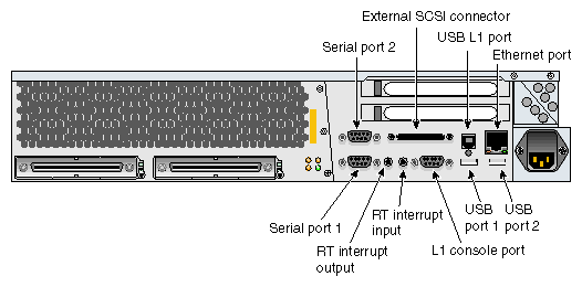
This appendix provides pin assignment information for non-proprietary connectors on the SGI Origin 300 server (refer to Table B-1 and Figure B-1).
Table B-1. SGI Origin 300 Server Connectors
Port | Connector | Pin Assignments |
|---|---|---|
Serial ports 1 and 2 | DB9 | Refer to “DB9 Connector”
|
L1 console port | DB9 | Refer to “DB9 Connector”
|
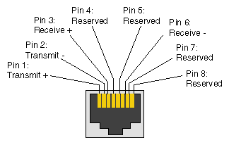
Ethernet port | RJ-45 | Refer to “RJ-45 Connector”
|
External SCSI port | SCSI 68-pin VHDCI | Refer to “External SCSI Port Connector”
|
RT interrupt input and output ports | Stereo jack | Refer to “Stereo Jack Connector Conductor”
|
USB ports 1 and 2 | USB type A | Refer to “USB Type A Connector”
|
USB L1 port | USB type B | Refer to “USB Type B Connector”
|
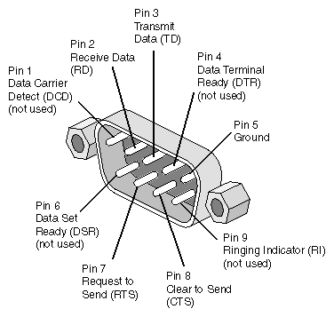
Figure B-2 shows the DB9 connector pin assignments. This connector is used for the L1 console port and serial ports 1 and 2 of the Origin 300 server.
Figure B-4 shows the external SCSI VHDCI connector pin locations for the external SCSI connector. Table B-2 lists the pin assignments for this SCSI connector.
Table B-2. SCSI VHDCI Pin Assignments
Pin Number | Signal Name | Pin Number | Signal Name |
|---|---|---|---|
1 | +DB (12) | 35 | -DB (12) |
2 | +DB (13) | 36 | -DB (13) |
3 | +DB (14) | 37 | -DB (14) |
4 | +DB (15) | 38 | -DB (15) |
5 | +DB (P1) | 39 | -DB (P1) |
6 | +DB (0) | 40 | -DB (0) |
7 | +DB (1) | 41 | -DB (1) |
8 | +DB (2) | 42 | -DB (2) |
9 | +DB (3) | 43 | -DB (3) |
10 | +DB (4) | 44 | -DB (4) |
11 | +DB (5) | 45 | -DB (5) |
12 | +DB (6) | 46 | -DB (6) |
13 | +DB (7) | 47 | -DB (7) |
14 | +DB (P0) | 48 | -DB (P0) |
15 | Ground | 49 | Ground |
16 | DIFFSENS | 50 | Ground |
17 | TERMPWR | 51 | TERMPWR |
18 | TERMPWR | 52 | TERMPWR |
19 | Reserved | 53 | Reserved |
20 | Ground | 54 | Ground |
21 | +ATN | 55 | -ATN |
22 | Ground | 56 | Ground |
23 | +BSY | 57 | –BSY |
24 | +ACK | 58 | –ACK |
25 | +RST | 59 | –RST |
26 | +MSG | 60 | –MSG |
27 | +SEL | 61 | –SEL |
28 | +CD | 62 | –CD |
29 | +REQ | 63 | –REQ |
30 | +IO | 64 | –IO |
31 | +DB (8) | 65 | -DB (8) |
32 | +DB (9) | 66 | -DB (9) |
33 | +DB (10) | 67 | -DB(10) |
34 | +DB (11) | 68 | -DB (11) |
Figure B-5 shows the stereo jack connector conductors that are used for the RT interrupt input and RT interrupt output ports of the Origin 300 server. Table B-3 lists the conductor assignments for the stereo jack connector.
Table B-3. Stereo Jack Connector Conductor Assignments
Conductor | Function |
|---|---|
Tip | Interrupt (active low) |
Ring | +5 V |
Sleeve | Chassis ground and cable shield |
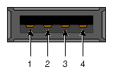
Figure B-6 shows the USB type A connector pin number locations and Table B-4 lists the pin assignments.
Table B-4. USB Type A Connector Pin Assignments
Signal | Color | Pin Number |
|---|---|---|
VCC | Red | 1 |
-Data | White | 2 |
+Data | Green | 3 |
Ground | Black | 4 |
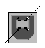
Figure B-7 shows the USB type B connector pin number locations and Table B-5 lists the pin assignments.
Table B-5. USB Type B Connector Pin Assignments
Signal | Color | Pin Number |
|---|---|---|
VCC | Red | 1 |
-Data | White | 2 |
+Data | Green | 3 |
Ground | Black | 4 |
