This chapter provides examples of the graphics system configurations in the following sections:
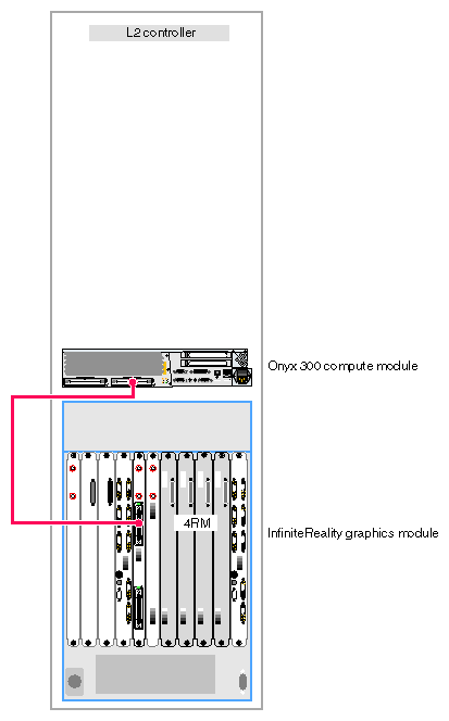
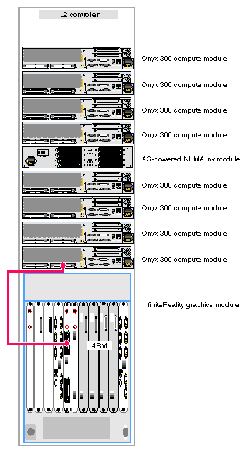
The Onyx 300 graphics system that does not contain a NUMAlink module is a single-rack system. It contains one InfiniteReality graphics module that has one or two graphics pipes. When the system contains only one graphics pipe, the lowest physical Onyx 300 compute module in the rack connects to pipe 0 as shown in Figure 3-1.
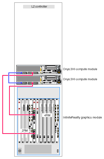
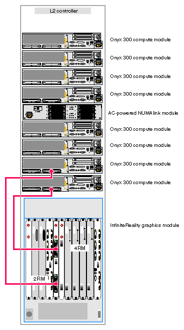
When the system contains two graphics pipes, the lowest physical Onyx 300 compute module connects to pipe 0, which is the pipe that can contain one, two, or four RM boards. Pipe 1, which can contain one or two RM boards, connects to the other Onyx 300 compute module. Refer to Figure 3-2.
Figure 3-1 illustrates a one-pipe Onyx 300 graphics system without a NUMAlink module.
Figure 3-2 illustrates a two-pipe Onyx 300 graphics system without a NUMAlink module.
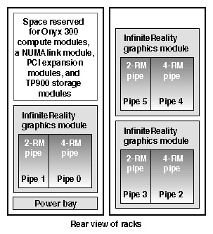
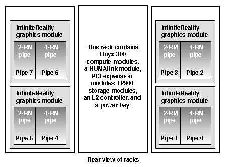
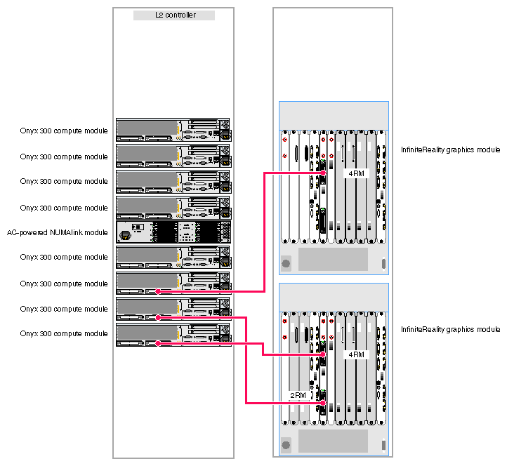
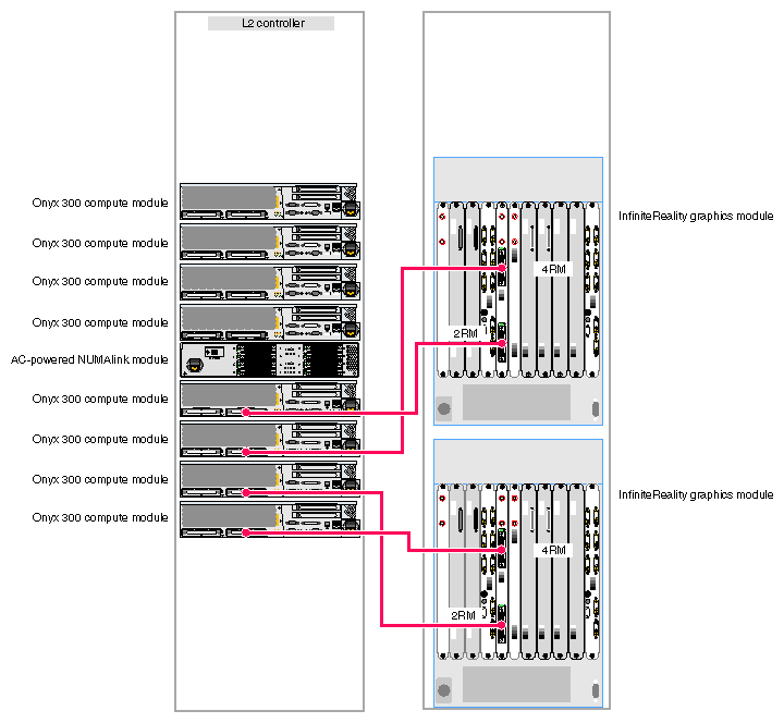
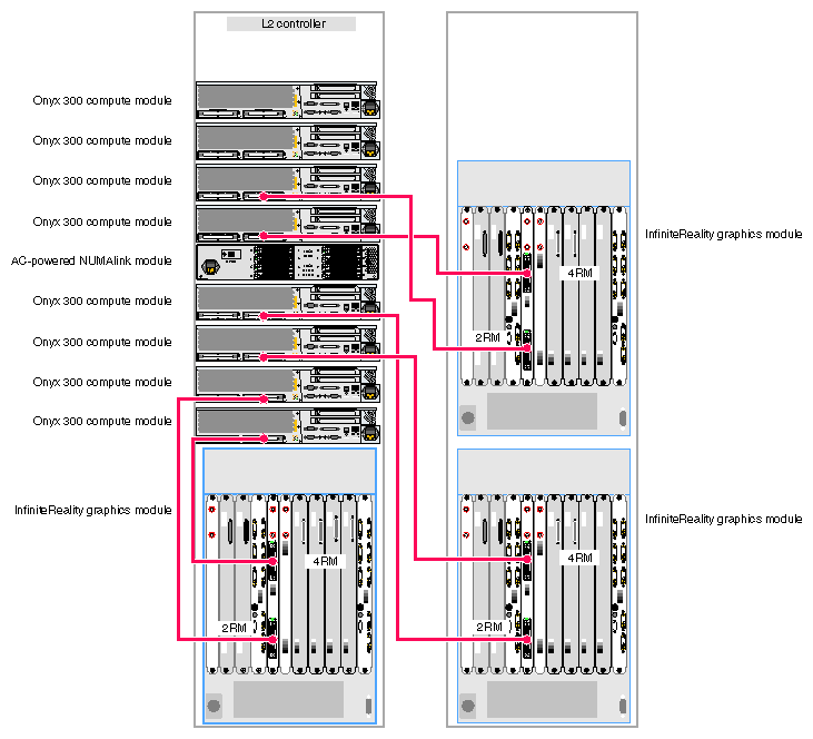
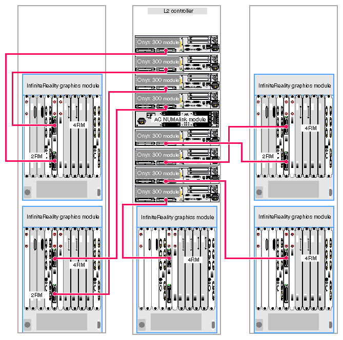
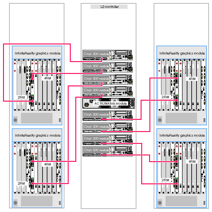
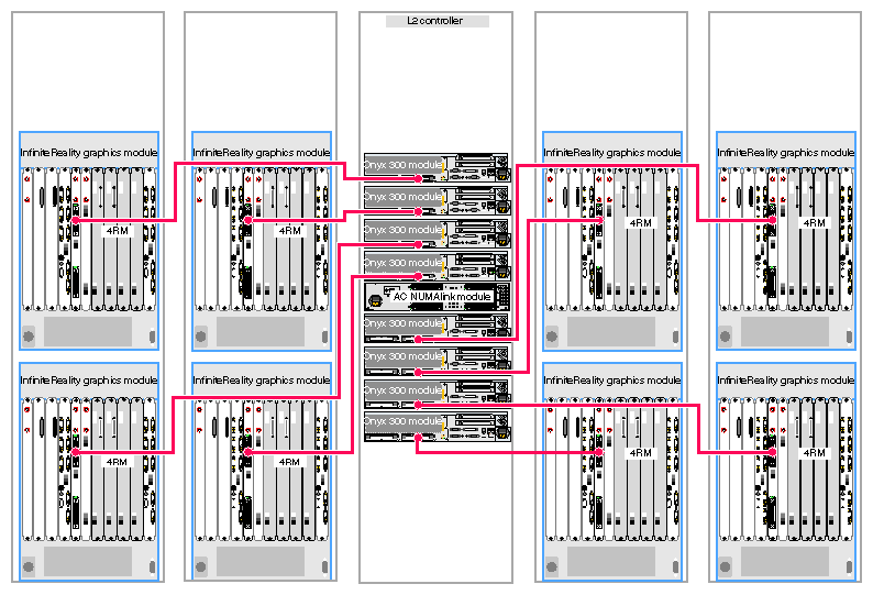
The Onyx 300 graphics system that contains a NUMAlink module is a single- or multiple-rack system. The single-rack system contains one or two graphics pipes. The multiple-rack system contains from one to eight graphics pipes. The number of racks depends on the number of graphics pipes and the number of RM boards in the graphics pipes. The maximum number of racks (eight 4-RM pipes) is five. This number does not include disk-storage racks.
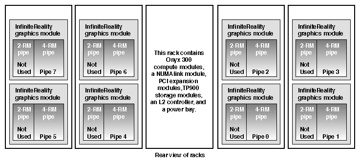
In a single-rack system, the pipes are numbered 0 and 1: the 4-RM pipe is pipe 0 and the 2-RM pipe is pipe 1. In multiple-rack systems, the pipes are numbered in the order shown in Figure 3-3 through Figure 3-5.
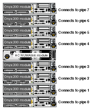
Each graphics pipe connects to an Onyx 300 compute module. The lowest physical Onyx 300 compute module (the global master) connects to pipe 0. The remaining pipes are connected to the Onyx 300 compute modules in ascending order (refer to Figure 3-6).
Figure 3-7 illustrates a one-pipe Onyx 300 graphics system with a NUMAlink module.
Figure 3-8 illustrates a two-pipe Onyx 300 graphics system with a NUMAlink module.
Figure 3-9 illustrates a three-pipe Onyx 300 graphics system with a NUMAlink module.
Figure 3-10 illustrates a four-pipe Onyx 300 graphics system with a NUMAlink module.
Figure 3-11 illustrates a six-pipe Onyx 300 graphics system with a NUMAlink module.
Figure 3-12 through Figure 3-14 provide examples of eight-pipe Onyx 300 graphics systems.
