This chapter shows you how to install and remove PCI boards. The following topics are covered:
To install PCI boards, you must use the PCI module. The PCI module is an optional Octane2 component that allows you to install and remove PCI boards without opening your workstation. If your workstation does not have a PCI module installed, a blank panel covers the module slot, as shown in Figure 4-1.

If your workstation has a PCI module installed, it protrudes from the rear of the workstation, as shown in Figure 4-2.

The Octane2 PCI module is a 5V system environment.
Total power for the PCI module (the sum of the power for all installed PCI boards) must not exceed 45.0W (average 15.0W per board).
For complete PCI module power specifications, go to “PCI Module Power Specifications” in Appendix B, “Technical Specifications.”
The PCI module supports full-size and half-size boards, and is compatible with boards that have extra-long I/O connectors. You you can install a maximum of three boards in the following combinations:
Two full-size boards and one half-size board
One full-size board and two half-size boards
Three half-size boards
To install or remove a PCI board, power off your workstation, remove any cables attached to the PCI module, and then attach the wrist strap.
Open the cover and press the power button (see A in Figure 4-3).
Unplug the power cable from the electrical outlet (B).
Press the monitor power switch to turn off your monitor (C).
Face the rear of your workstation.
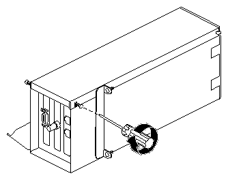
Remove any cables from the PCI module, as shown in Figure 4-4.


| Caution: The components inside your workstation are extremely sensitive to static electricity; you must wear the wrist strap while replacing parts. |
Unroll the first two folds of the band (see A in Figure 4-5).
Wrap the exposed adhesive side firmly around your wrist (B), unroll the rest of the band, then peel the liner from the copper foil at the opposite end.
Attach the copper foil to any exposed electrical ground, such as a metal part of the workstation (C).

To install or remove PCI boards, you must remove the PCI module from the workstation.
Loosen the two captive screws that secure the PCI module to the workstation, as shown in Figure 4-6, until they are disconnected from the chassis.
Pull the release lever toward you and to the right, as shown in Figure 4-7.
Remove the PCI module by sliding it out of the workstation, as shown in Figure 4-8, then place it on a dry, antistatic surface, such as your desk.

Caution: The compression connector on the back of the PCI module is delicate and easily damaged. Do not touch or bump the gold area of the compression connector (see Figure 4-9). For information about compression connectors, see Appendix A.
Place a cap on the compression connector on the back of the PCI module, as shown in Figure 4-10 (compression connector caps are included with the workstation).


If you removed the PCI module from your workstation, go to step 1, below. If the PCI module is still installed in your workstation, go to “Preparing the Workstation” and follow the instructions through removing the PCI module.
Turn the PCI module on its side, as shown in Figure 4-11.
Loosen the screws that secure the PCI module door, but do not remove them.
Pull the PCI module door up and off, as shown in Figure 4-12.
The release hinge allows the module door to slide up and off.


PCI physical slots and PCI slots identified by the system software have the same identification numbers (see Figure 4-13).
The top slot is PCI ID #1.
The middle slot is PCI ID #2.
The bottom (half-sized) slot is PCI ID #3.

If you did not prepare your workstation for a PCI board installation, go to “Preparing the Workstation” and follow the instructions through removing the PCI module. Then return to this page and follow these steps:
Remove the screw from the blank I/O panel that covers the slot you want to use for the PCI board, as shown in Figure 4-14.
Remove the blank I/O panel by pulling it up, as shown in Figure 4-15.
Use the metal knob on the side of the blank panel to help lift it out of the PCI module.
Store the I/O blank panel in a safe place.

Note: If you remove an installed PCI board and do not replace it with another board, reinstall the blank panel.
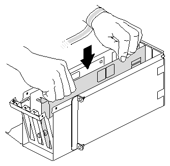
Insert the PCI board into the connector in the PCI module, as shown in Figure 4-16.
Push gently but firmly until the PCI board snaps into place.
Note: If the board has an extra-long connector that makes it difficult to insert, skip to the next section, “Opening the I/O Door for Extra-Long Connectors”.
Insert and tighten the screw that secures the PCI board to the PCI module, as shown in Figure 4-17.
Place the hinged door on the PCI module, as shown in Figure 4-18.
Tighten the I/O door screws, as shown in Figure 4-19.


Go to “Installing the PCI Module”.
If boards are installed in the PCI module, remove the I/O panel screws that secure the boards, as shown in Figure 4-20.
Completely remove the screws that secure the I/O door to the PCI module, as shown in Figure 4-21.
Slide open the I/O door to expand the PCI module, as shown in Figure 4-22.
Insert the PCI board into the connector in the PCI module, as shown in Figure 4-23.
Press gently but firmly until the board snaps into place.
Close the I/O door, as shown in Figure 4-24.
Insert and tighten the screws that secure the I/O door, as shown in Figure 4-25.
Insert and tighten the screws that secure all PCI boards to the I/O panel, as shown in Figure 4-26.
Reinstall the PCI module door, as shown in Figure 4-27.
Figure 4-27. Reinstalling the PCI Module Door, as shown in Figure 4-28.

Tighten the PCI module door screws.


Go to “Installing the PCI Module”.
If you did not prepare your workstation for removal of a PCI board, go to “Preparing the Workstation”, and follow the instructions through removing the PCI module. Then return to this page and follow these steps:
Remove the screw that secures the PCI board to the module, as shown in Figure 4-29.
If you have a board with an extra-long connector, go to “Opening the I/O Door for Extra-Long Connectors”. Otherwise, go to step 2.
Grasp the PCI board on the top edge to extract it, as shown in Figure 4-30.
Pull up until the board releases.
If the board is firmly installed, it may be hard to remove. If it is very hard to remove, go to “Opening the I/O Door for Extra-Long Connectors”.
If you want to install another PCI board, go to “Installing a PCI Board”.
If you are not installing another PCI board in the same slot, you must insert an I/O blank panel as described in steps 4 and 5.
Insert, but do not tighten, the screws securing the I/O door to the PCI module, as shown in Figure 4-31.
Install an I/O blank panel in the I/O door in place of the PCI board, as shown in Figure 4-32.
Use the knobs on the back of the blank panel to position it. Make sure you place the tip of the I/O blank panel inside the groove at the bottom of the PCI module. Do not position the tip outside the groove.
Attach the blank panel to the I/O door with the screw you removed in step 1, as shown in Figure 4-33.
Reinstall the PCI module door, as shown in Figure 4-34.
Tighten the door screws, as shown in Figure 4-35.


Go to “Installing the PCI Module”.
Remove the screws that secure any other PCI boards to the module, as shown in Figure 4-36.
Remove the screws that secure the I/O panel door to the PCI module, as shown in Figure 4-37.
Slide open the I/O door, as shown in Figure 4-38.
This provides clearance for the I/O connector at the end of the PCI board.
Now you can easily remove the board. If two other boards are installed at the sides of the PCI module, you can now grasp their edges.
Grasp the PCI board on the top edge to extract it.
Pull up until the board releases, Figure 4-39.
If the board is firmly installed, it may be difficult to remove.
If you want to install another PCI board, go to “Installing a PCI Board”.
If you are not installing another PCI board in the same slot, insert an I/O blank panel, then go to the next step.
Close the I/O door, as shown in Figure 4-40.
Insert, but do not tighten, the screws holding the I/O door to the PCI module, as shown in Figure 4-41.
Install an I/O blank panel in the I/O door in place of the PCI board, as shown in Figure 4-42.
Use the knobs on the back of the blank panel to position it. Make sure you place the tip of the I/O blank panel inside the groove at the bottom of the PCI module. Do not position the tip outside the groove.
Attach the blank panel to the I/O door with the screw you removed earlier in this section, as shown in Figure 4-43.
Reinstall the PCI module door, as shown in Figure 4-44.
Tighten the PCI module door screws, as shown in Figure 4-45.


Go to “Installing the PCI Module”.
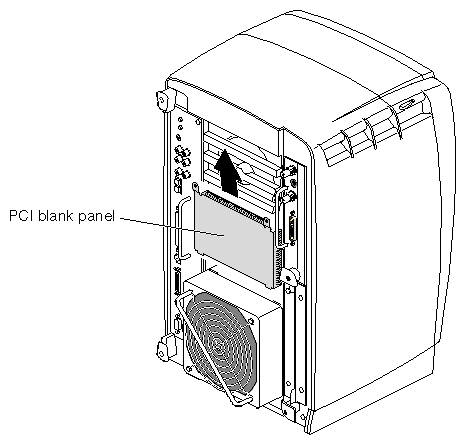
If you are installing a PCI module for the first time, you have to remove the blank panel.
Using a Phillips screwdriver, remove the screws from the blank panel, as shown in Figure 4-46.
Using a flathead screwdriver, place the tip of the screwdriver in the slot at the top and middle of the blank panel.
Pull the panel outward and lift it up and out, as shown in Figure 4-47.
Note: Save the blank panel in case you want to remove the PCI module at a later time. Either the PCI module or the blank panel must be installed at all times.
Remove the cap from the compression connector on the back of the PCI module, and save it for future use, as shown in Figure 4-48.
Insert the PCI module in your workstation, as shown in Figure 4-49, then push it until the tabs are flush with the chassis.
Close the release lever by pushing it to the left until it is parallel with the PCI module, as shown in Figure 4-50.
Tighten the captive screws that secure the PCI module to the workstation, as shown in Figure 4-51.
Connect any PCI cables to the PCI connectors, as shown in Figure 4-52.
Remove the wrist strap.


You are finished installing the PCI module.
Face the front of your workstation.
Connect the workstation's power cable to an electrical outlet (see A in Figure 4-53).
Press the power button (B) to power on your workstation.
Press the monitor power switch (C) to power on your monitor.

For instructions on checking the PCI board installation, see the Octane2 PCI Module Installation Guide.
If your PCI board does not function properly, repeat the installation procedure.
If you repeat the installation procedure and your PCI board still does not function properly, call your authorized SGI service representative.