This chapter provides information about adding or removing components from your Silicon Graphics Fuel visual workstation. The topics covered include:
“Replacing Chassis Components”

Caution: For your own safety and to avoid damage to your equipment, do not attempt to install or remove components that are not listed in this chapter.
Replacement parts are available directly from your local service provider. Contact the SGI support office for more information.
This section shows you how to open the workstation for service, protect the components from static damage, and return the system to operation. The following topics are covered:
To prepare your workstation for service, follow these steps:
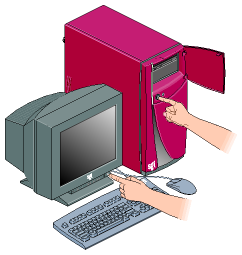
If you are logged in to the workstation, log out. Then, press the power buttons to power off your workstation and monitor (refer to Figure 4-1).
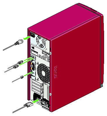
Disconnect all of the cables from the rear of the workstation. Be sure to note where each cable is connected, so that you can re-connect them correctly when you have finished servicing the system. Refer to Figure 4-2.
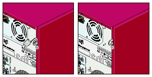
If your system has a locking loop installed, remove the padlock (refer to Figure 4-3).
If no lock is installed, proceed to the next section.
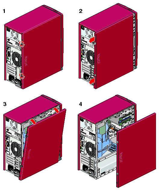
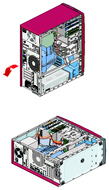
Follow these steps to remove the side panel (refer to Figure 4-4):
Loosen the two captive thumbscrews that secure the side panel to the workstation.
Pull the side panel toward the rear of the workstation.
Swing the top edge of the panel away from the enclosure.
Lift the side panel up and off of the bottom edge of the enclosure.
Carefully lay the system down on its right side, as shown in Figure 4-5. This makes it easier to access the internal components of the workstation.
| Warning: The heat sinks on the motherboard get very hot. Wait five minutes after powering off your workstation before you touch any internal components. Touching the motherboard heat sinks could result in burns if a cooling-off period is not observed. |
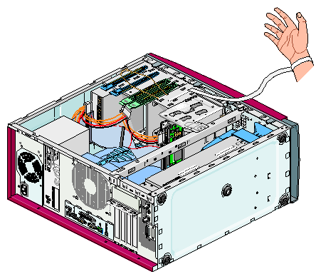
| Caution: The components inside your workstation are extremely sensitive to static electricity. Always wear the wrist strap when you work with parts inside your workstation. Follow these steps to use the wrist strap (refer to Figure 4-6): |
Unroll the first two folds of the band.
Wrap the exposed adhesive side firmly around your wrist, unroll the rest of the band, and then peel the liner from the copper foil at the opposite end.
Attach the copper foil to an exposed electrical ground, such as a metal part of the chassis.
After you remove the side panel and attach the wrist strap, you can install or remove internal parts of the workstation. Table 4-1 contains a list of all of the internal components that you can install or remove and the procedure associated with each one.
| Caution: Do not attempt to install or remove components that are not listed in Table 4-1. Components not listed in Table 4-1 must be installed or removed by a qualified SGI field engineers. |
Table 4-1. C ustomer-replaceable Components and Service Procedures
Component | Procedure |
|---|---|
Memory DIMMs: DIMM 256 MB DIMM 512 MB DIMM 1 GB | “Installing or Removing a Memory DIMM”
|
Internal hard disk drives: 18 GB, 10000 RPM 36 GB, 10000 RPM 73 GB, 10000 RPM | “Installing or Removing Internal Hard Disk Drives”
|
Removable media drives: CD-ROM drive Internal DAT drive | “Installing or Removing a Removable Media Drives”
|
Cooling system: Exhaust fan Air duct PCI and graphics fan housing Hard drive fan | “Replacing Cooling System Components”
|
Enclosure Components: Chassis feet Bezel assembly Switch/LED assembly | “Replacing Chassis Components”
|
When you finish installing or removing internal components, proceed to the next section.
When you finish installing or removing components, follow these steps to return the workstation to service:
If the workstation is lying on its side, carefully stand it up.
Disconnect the anti-static wrist strap from the workstation.
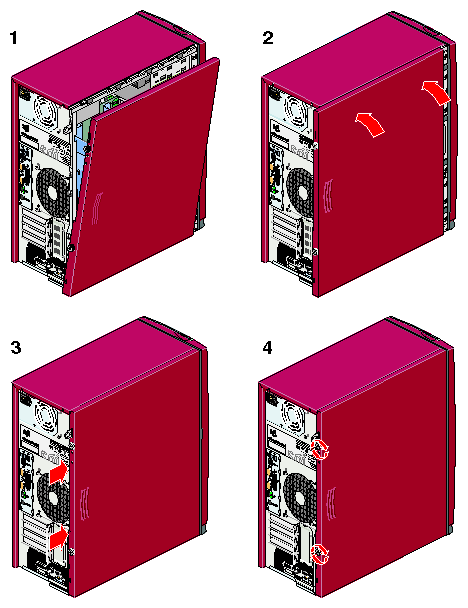
Install the side panel (refer to Figure 4-7) as follows:
Position the side panel so that the groove in the bottom edge of the side panel is resting on the rail in the bottom of the enclosure.
Swing the top edge of the side panel up into place against the top edge of the enclosure.
Slide the side panel toward the front of the workstation until it is firmly seated.
Tighten the two captive thumbscrews that secure the side panel to the workstation.
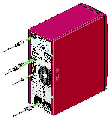
Connect all of the system cables to the rear of the enclosure (refer to Figure 4-8).
If your workstation is equipped with a padlock or Kensington lock, lock the workstation. Refer to “Installing Locking Devices” for more information.
If your workstation does not boot correctly, refer to Chapter 5, “Troubleshooting and Diagnostics”.
The Silicon Graphics Fuel visual workstation is configured with a minimum of 512 MB of memory and a maximum of 4 GB of memory. The memory DIMMs are installed in four DIMM sockets on the system board, which are divided into two DIMM pairs. The instructions in the following sections assume that you know which slots to install the memory DIMMs in. For information about DIMM configurations and placement rules, refer to “Memory DIMMs” in Chapter 3.
| Note: If you have not already done so, prepare your system for service before installing or removing a DIMM. Refer to “Preparing the Workstation for Service”. |
This section provides instructions for the following procedures:
Removing a DIMM
Installing a DIMM
Verifying Memory Installation
To remove a DIMM, follow these steps:
Remove the motherboard air duct. Refer to “Replacing the Motherboard Air Duct”.
Locate the DIMM that you want to remove.
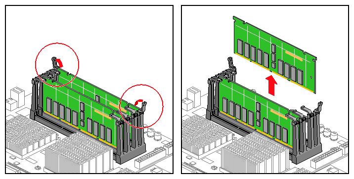
Pull up on the latches at the end of the DIMM socket (refer to Figure 4-9). The DIMM will partially eject from the socket.
Lift the DIMM up and out of the enclosure.
Place the DIMM in an anti-static bag and store it in a secure location.

Note: Both sockets in a DIMM bank must be either empty or populated. If you remove one DIMM and do not plan to replace it immediately, also remove the other DIMM in the bank and replace it when you install a new DIMM. Install a new DIMM or return the system to service, as follows:
To replace the DIMM immediately, proceed to the next section, “Installing a DIMM”.
To return the system to service, proceed to the next step.

Note: The workstation will not function if there are no memory DIMMs installed. Two memory DIMMS of equal size must be installed in DIMM pair number 1.
Install the motherboard air duct. Refer to “Replacing the Motherboard Air Duct”.
Refer to “Returning the Workstation to Service” to complete this procedure.
To install a DIMM, follow these steps:
| Caution: DIMMs are sensitive to static electricity. Be sure to wear the anti-static wrist strap while you complete these steps. |
If you have not already done so, remove the motherboard air duct. Refer to “Replacing the Motherboard Air Duct”.
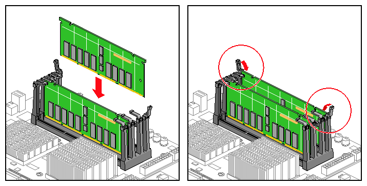
Rotate the ejector latches on each end of the socket so that they stand straight up, as shown in Figure 4-10.
If there is a plastic blank in the DIMM socket, remove it. These blanks are installed in the factory to prevent damage to the socket during shipping.
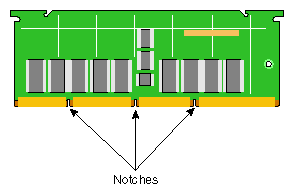
Align the DIMM with the socket. Make sure that the notches on the bottom of the DIMM align with the protrusions in the bottom of the socket. Refer to Figure 4-11.
Seat the DIMM in the socket and press down. If you have seated the DIMM correctly, the ejector latches will swing up and click into place in the notches on the ends of the DIMM.
If necessary, repeat steps 2 through 5 to install a second DIMM.
Ensure that both sockets in the DIMM bank are full. DIMMs must be installed in pairs.
Install the motherboard air duct in the enclosure. Refer to “Replacing the Motherboard Air Duct”.
This completes the memory DIMM installation. To return the workstation to service, refer to “Returning the Workstation to Service”.
To verify the memory installation, follow these steps:
After you power on the system, select System Manager > Hardware and Devices > About This System from the Toolchest and check the amount of memory displayed for Main Memory. The displayed memory should equal the original amount of memory minus any memory you removed, plus the amount of memory you installed.
If the amount of memory is incorrect, power off the system and check the following:
Check the angle of the DIMMs. They should be upright and completely seated.
Ensure that each bank is populated with two DIMMs, and that they are the same type. You must have an even number of DIMMs installed.
The Silicon Graphics Fuel visual workstation can have as many as three internal hard disk drives. The instructions in the following sections assume that you know where to install the hard disk drive.
For information about drive placement rules, refer to “Internal Hard Disk Drives ” in Chapter 3.
To install or remove a disk drive in the lower drive cage, refer to “Installing or Removing a Drive in the Lower Hard Disk Drive Cage ”.
To install or remove a disk drive in the upper drive cage, refer to “Installing or Removing a Drive in the Upper Hard Disk Drive Cage”.

Note: If you have not already done so, prepare your system for service before installing or removing an internal hard disk drive. Refer to “Preparing the Workstation for Service”.
This section provides instructions for the following procedures:
Opening the Lower Drive Cage
Installing a Disk Drive in the Lower Drive Cage
Removing a Disk Drive from the Lower Drive Cage
Closing the Lower Drive Cage
Follow these steps to open the lower drive cage:
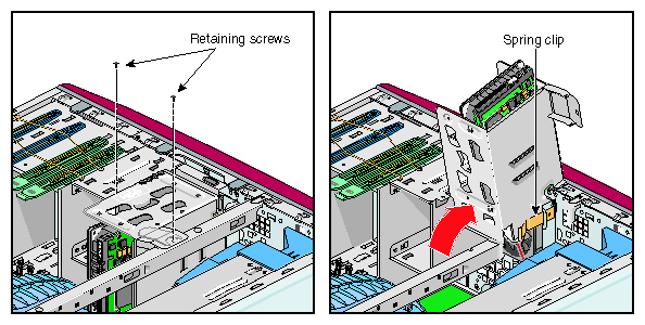
Disconnect the SCSI and power cables from any disk drives that are installed in the lower drive cage.
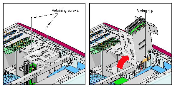
Remove the two screws that secure the drive cage to the chassis. Then swing the drive cage up and out of the chassis until it locks into place. Refer to Figure 4-12.
Follow these steps to install a disk drive in the lower drive cage:
If a disk drive is already installed in the position where you will install the new disk, you must remove it. Refer to “Removing a Disk Drive from the Lower Drive Cage”.
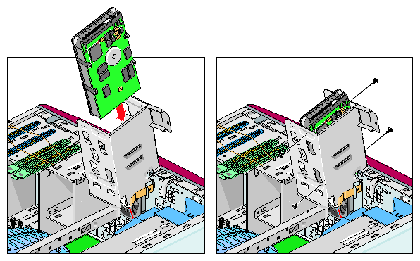
Remove the four hard drive screws that stored on the side of the lower drive cage. You will use these screws to install the disk drive. If you a
Orient the disk drive so that the SCSI cable connector is on the left as you look at the rear of the drive. Then slide the drive into the drive cage so that it rests on the drive rails. Refer to Figure 4-13.
Align the holes in the side of the drive cage with the holes in the sides of the disk drive. Then install the four Phillips screws that secure the drive to the drive cage. Refer to Figure 4-13.

Caution: The hard drive screws must be 6-32 and no longer than 3/16-in. Using screws that do not meet this specification will damage your drive. When you have finished installing the disk drive, close the lower drive cage. Refer to “Closing the Lower Drive Cage”.
Follow these steps to remove a disk drive from the lower drive cage:
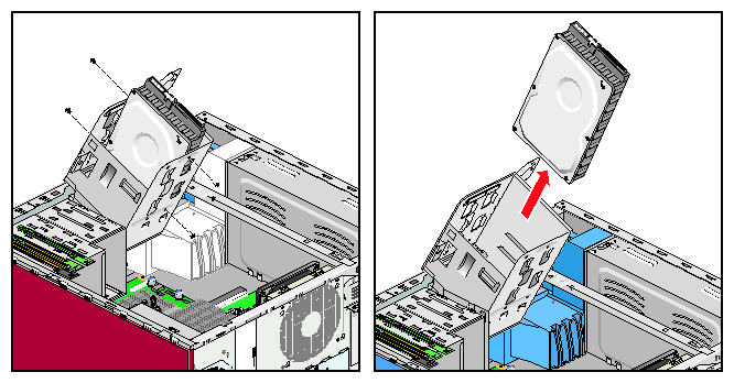
Remove the four Phillips screws that secure the drive you are removing to the drive cage. Then grasp the disk drive and slide it up and out of the drive cage. Refer to Figure 4-14.
If you are replacing the disk drive with a new drive, refer to “Installing a Disk Drive in the Lower Drive Cage”.
Proceed to the next section, “Closing the Lower Drive Cage”.
Follow these steps to close the lower drive cage:
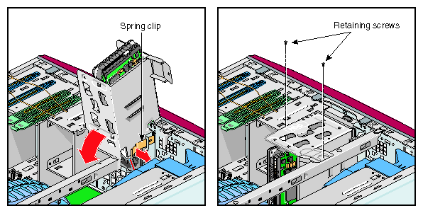
Release the drive cage latch and swing the drive cage into the enclosure. Then install the two Phillips screws that secure the drive cage to the chassis. Refer to Figure 4-15.
Connect the SCSI and power cables to the rear of the disk drive(s) in the lower drive cage. Refer to Appendix C, “Internal Cabling Diagrams”.
This completes the hard disk installation or removal. To return the workstation to service, refer to “Returning the Workstation to Service”.
This section provides instructions for the following procedures:
Installing a Disk Drive in the Upper Drive Cage
Removing a Disk Drive from the Upper Drive Cage
Follow these steps to install a disk drive in the upper drive cage:
If you have not already done so, prepare your system for service.
Refer to “Preparing the Workstation for Service”. Then remove the bezel of the workstation. Refer to “Replacing the Bezel Assembly”.If a disk drive is already installed in the upper drive cage, you must remove it before you can install the new disk drive. Refer to “Removing a Disk Drive from the Upper Drive Cage”. If you remove a drive from the upper drive bay, save the blue drive rails. You will need them to install the new drive.
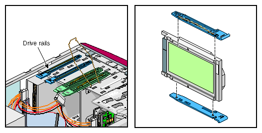
Locate the blue drive rails. They are stored on the side of the upper drive cages. Refer to Figure 4-16.
Attach the blue drive rails to the sides of the disk drive by inserting the pins into the openings in the sides of the drive. The drive rails are marked “L” and “R” to show the side of the drive to which they should be attached. Refer to Figure 4-16
Remove the screw that secures the drive cage cover to the front of the enclosure. Refer to Figure 4-17.
Align the drive rails with the slots in the side of the drive cage and slide the drive into the drive cage. Then install the drive cage cover. Refer to Figure 4-17.
Connect the SCSI and power cables to the rear of the disk drive. Refer to Appendix C, “Internal Cabling Diagrams”.
Install the bezel on the front of the workstation.
Refer to “Replacing the Bezel Assembly”.This completes the hard disk drive installation. To return the workstation to service, refer to “Returning the Workstation to Service”.
Follow these steps to remove a disk drive from the upper drive cage:
If you have not already done so, prepare your system for service. Refer to “Preparing the Workstation for Service”.
Remove the bezel of the workstation. Refer to “Replacing the Bezel Assembly”.
Disconnect the SCSI and power cables from the rear of the disk drive.
Remove the screw that secures the drive cage cover to the front of the enclosure.
Squeeze the tabs on the drive rails against the sides of the drive. Then slide the drive out of the drive cage. Refer to Figure 4-18.
If you are replacing the disk drive with a new drive, refer to “Installing a Disk Drive in the Lower Drive Cage”.
If you are leaving the drive cage empty, install the drive cage cover on the front of the enclosure. Refer to Figure 4-19.
Install the bezel on the front of the workstation. Refer to “Replacing the Bezel Assembly”.
This completes the hard disk drive removal. To return the workstation to service, refer to “Returning the Workstation to Service”.
The Silicon Graphics Fuel visual workstation supports two removable media drives: a 40X CD-ROM drive, and a 20-GB 4-mm Digital Audio SCSI tape drive. The following procedures apply to both of these drives. The CD-ROM drive should be installed in the upper opening in the drive bay, and the DAT drive should be installed in the lower opening.
| Note: If you have not already done so, prepare your system for service. Refer to “Preparing the Workstation for Service”. |
Follow these steps to install a removable media drive:
Remove the bezel from the front of the enclosure. Refer to “Replacing the Bezel Assembly”.
If a removable media drive is already installed in the position where you will install the new drive, you must remove it before you can install the new drive. Refer to “Removing a Removable Media Drive”. If you remove a drive from the drive bay, save the drive rails. You will need them to install the new drive.
If an EMI shield is installed in the position where you will install the drive, remove it. To remove the EMI shield, place your finger in the hole and pull straight out.
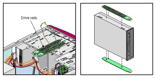
Locate the green drive rails. They are stored on the side of the drive cages.
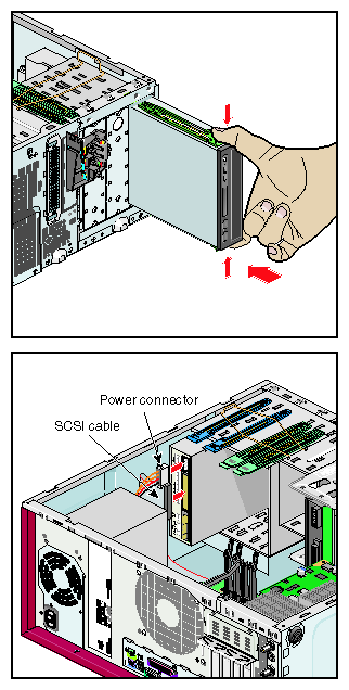
Refer to Figure 4-20.Attach the 5.25-in. green drive rails to the sides of the disk drive by inserting the pins into the openings in the sides of the drive. Refer to Figure 4-20.
Align the drive rails with the slots in the side of the drive cage and slide the drive into the drive cage. Refer to Figure 4-21.
Connect the SCSI cable to the rear of the drive as follows (refer to Appendix C, “Internal Cabling Diagrams”):
Connect the CD-ROM drive to the 50-pin SCSI cable. Connect the drive to the connector at the end of the cable.
Connect the DAT drive to the 68-pin SCSI cable to which the hard disk drives are connected.
Connect a power cable to the rear of the drive. Refer to Figure 4-21 and Appendix C, “Internal Cabling Diagrams”.

Note: The CD ROM drive is shown in Figure 4-21. The DAT drive should be installed in the bay below the CD ROM drive using the same procedure, but a different SCSI cable. For complete SCSI and power cabling diagrams, refer to Appendix C, “Internal Cabling Diagrams”. Remove the drive bay cover that corresponds to the bay you installed the new drive in from the bezel. Place the drive bay cover in a secure location.
Install the bezel on the front of the enclosure. Refer to “Replacing the Bezel Assembly”.
This completes the removable media drive installation. To return the workstation to service, refer to “Returning the Workstation to Service”.
Follow these steps to remove a removable media drive:
Remove the bezel from the front of the enclosure. Refer to “Replacing the Bezel Assembly”.
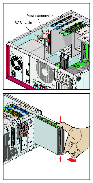
Disconnect the SCSI and power cables from the rear of the drive.
Refer to Figure 4-22.
Note: Figure 4-22 shows the CD ROM drive. The procedure is the same for the DAT drive, but the drive is located in the lower opening in the removable media drive bay. Squeeze the tabs on the drive rails against the sides of the drive. Then slide the drive out of the drive cage. Refer to Figure 4-22.
If you are replacing the drive with a new drive, refer to “Installing a Removable Media Drive”.
If you are leaving the drive bay empty, install the EMI shield in the opening left by the drive.
Install the drive bay cover in the bezel to cover the empty drive bay. Then install the bezel on the front of the enclosure. Refer to “Replacing the Bezel Assembly”.
This completes the removal of the removable media drive. To return the workstation to service, refer to “Returning the Workstation to Service”.
The Silicon Graphics Fuel visual workstation can house as many as 4 PCI boards. These instructions assume that you know what slot you need to install the PCI board in. For more information of PCI board placement rules and configurations, refer to “PCI Boards ” in Chapter 3.
| Note: If you have not already done so, prepare your system for service. Refer to “Preparing the Workstation for Service”. |
This section provides instructions for the following procedures:
Accessing the PCI Boards
Installing a PCI Board
Removing a PCI Board
Completing the PCI Board Installation or Removal
Follow these steps to access a PCI board:
Disconnect the SCSI and power cables from any disk drives that are installed in the lower drive cage.
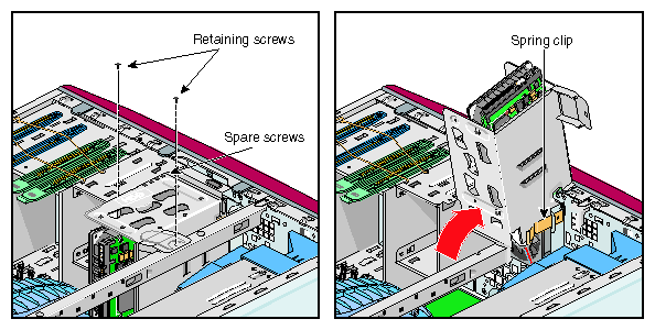
Remove the two screws that secure the drive cage to the chassis. Then swing the drive cage up and out of the chassis until it locks into place. Refer to Figure 4-23.
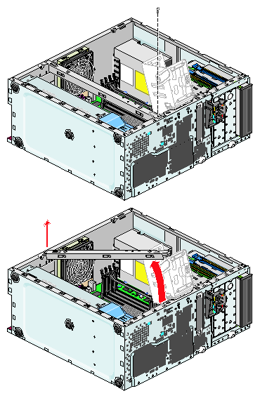
Remove the screw that secures the chassis stiffening bar to the chassis. Then swing the chassis stiffening bar toward the rear of the chassis and remove it.
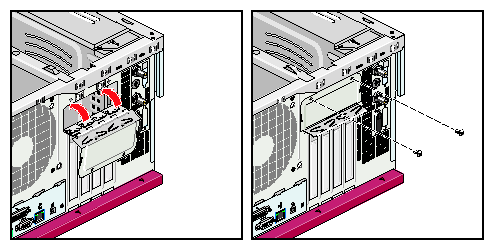
Refer to Figure 4-24.Remove the two screws that secure the PCI gate. Then open the PCI gate. Refer to Figure 4-25.
To install a PCI board, proceed to the next section. To remove a PCI board, refer to “Removing a PCI Board”.
Follow these steps to install a PCI board:
If a PCI blank module or another PCI board is installed in the slot where you will install the new PCI board, you must remove it before you can install the new PCI board.

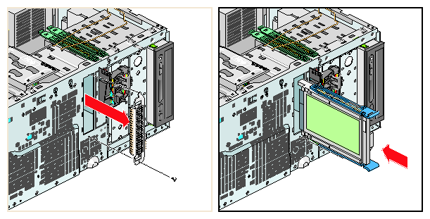
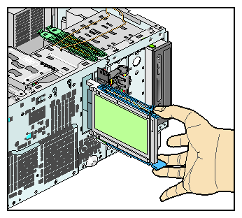
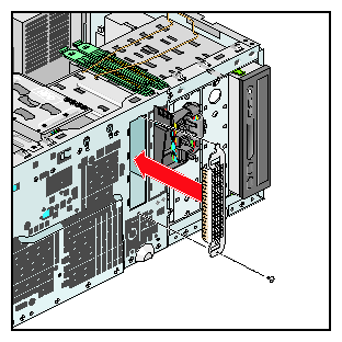
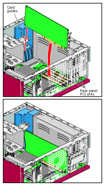
Note: Store the PCI blank module in a safe place. If you remove a PCI board and do not replace it, you will need to install the PCI blank module to maintain proper airflow in the chassis. Align the PCI board with the PCI slot. Then lower the PCI board into the chassis with the connector end angled slightly downward. Refer to Figure 4-26.
Align the connector in the PCI gate. Then press down firmly on the PCI board until it is fully seated in the PCI slot. Refer to Figure 4-26.
To complete the installation of the PCI board, proceed to “Completing the PCI Board Installation or Removal”.
Follow these steps to remove a PCI board:
Grasp the top edge of the PCI board firmly. Then lift the PCI board straight up until it clears the PCI slot. Remove the PCI from the enclosure and place it in a safe location.
If you will not replace the PCI board with another PCI board immediately, you must install a PCI blank module in the slot to maintain airflow in the enclosure.
To complete the removal of the PCI board, proceed to “Completing the PCI Board Installation or Removal”.
Follow these steps to complete the PCI board installation or removal:
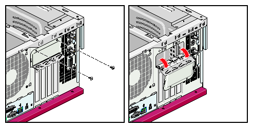
Close the PCI gate. Then install the 2 screws that secure the PCI gate.
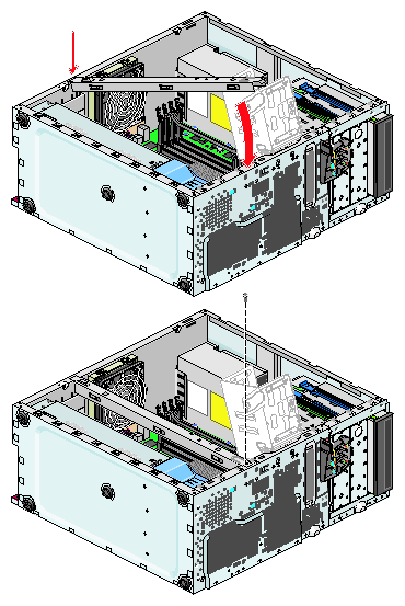
Refer to Figure 4-27.Insert the tab on the chassis stiffening bar into the hole in the chassis and swing the chassis stiffening arm down into place. Then install the screw that secures the chassis stiffening arm to the chassis. Refer to Figure 4-28.
Close the lower drive cage. Refer to “Closing the Lower Drive Cage”. Then install the two screws that secure the drive cage to the chassis.
Connect the SCSI and power cables to the drive(s) in the lower drive cage. Refer to Appendix C, “Internal Cabling Diagrams”.
This completes the PCI board installation or removal. To return the workstation to service, refer to “Returning the Workstation to Service”.
Refer to the documentation that came with the device for more information on connecting it to your workstation.
You can lock the Silicon Graphics Fuel visual workstation can be locked in two ways, which are explained in the following sections:
Installing a Locking Loop and a Padlock
Installing a Kensington Lock
This section provides information about the function and installation of both types of locks.
| Note: Locks are not supplied with the workstation. |
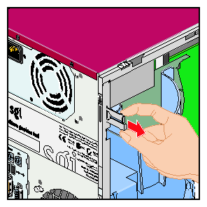
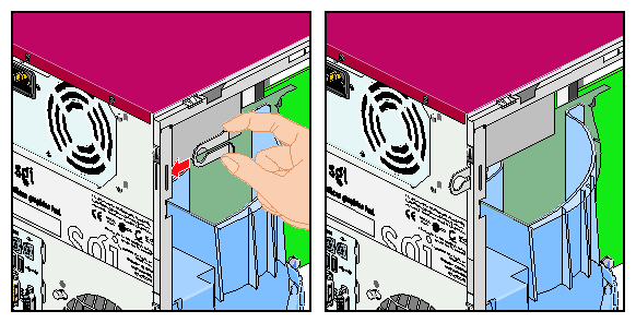
The locking loop allows you to lock the workstation case to prevent the internal components from being removed or tampered with. The locking loop is located at the rear of the workstation side panel (refer to Figure 4-29). The loop is stored in a slot in the chassis and must be installed in the locking slot to be used.
Follow these steps to install the locking loop:
Remove the side panel from your workstation. Refer to “Preparing the Workstation for Service”.

Note: If you are only installing the locking loop, you do not need to disconnect all of the cables from the rear of the chassis or lay the chassis down. Locate the locking loop storage slot; then remove the loop from its storage position by squeezing the two hooks together and pulling the loop out of the chassis. Refer to Figure 4-29.
Locate the locking slot at the rear of the chassis; then insert the narrow end of the locking loop into the slot from inside the chassis and push it outward until it snaps into place. Refer to Figure 4-30.
Install the side panel on your workstation. Refer to “Returning the Workstation to Service”.
Install a padlock in the locking loop to prevent the side panel from being removed. This completes the locking loop installation.
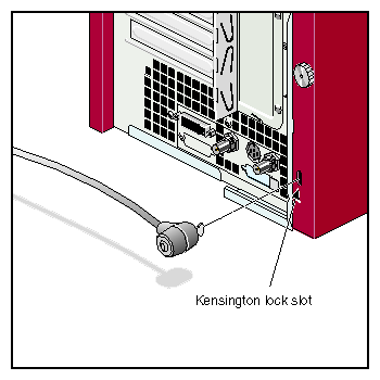
The workstation is equipped with a Kensington lock slot. The lock slot is located on the rear edge of the removable side panel, near the bottom. This slot allows you to install a Kensington lock to secure the workstation to the work area. For more information on installing a Kensington lock, refer to the documentation supplied with the lock.
| Note: A Kensington lock is not included with the workstation. |
This section provides instructions for the following procedures:
Replacing the Motherboard Air Duct
Replacing the Exhaust Fan
Replacing the Hard Disk Drive Fan
Replacing the PCI and Graphics Fan Housing

Caution: Never operate the unit without all of the cooling system components in place. Operating the workstation without the proper cooling equipment may damage the internal components.
Follow these steps to replace the motherboard air duct:
| Note: If you have not already done so, prepare your system for service. Refer to“Preparing the Workstation for Service”. |
Disconnect the SCSI and power cables from the disk drive(s) installed in the lower drive cage.
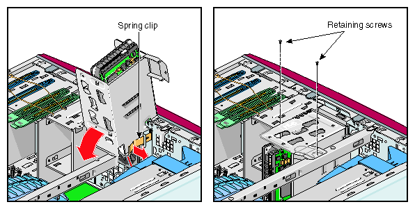
Remove the two screws that secure the drive cage to the chassis. Then swing the drive cage up and out of the enclosure until it locks into place. Refer to Figure 4-32.
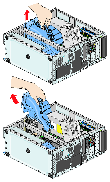
Grasp the handle of the air duct and tilt the rear edge of the duct upward. Then slide the duct out of the enclosure. Refer to Figure 4-33.
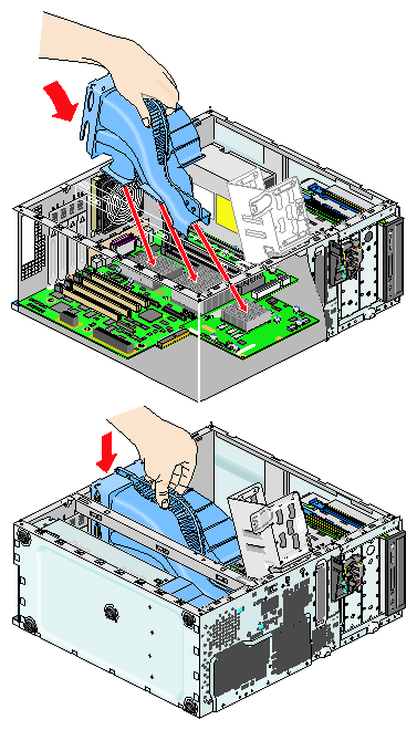
Align the narrow end of the replacement duct over the PIMM heat sink. Then, swing the duct down until it snaps into place.
Ensure that the duct is properly seated on the heatsinks and that the rear edge is properly seated on the top edge of the exhaust fan. Refer to Figure 4-34.
Release the drive cage latch and swing the drive cage down into the enclosure. Then install the two Phillips screws that secure the drive cage to the chassis. Refer to Figure 4-35
Connect the SCSI and power cables to the rear of the disk drive(s) in the lower drive cage. Refer to Appendix C, “Internal Cabling Diagrams”.
This completes the replacement of the motherboard air duct. To return the workstation to service, refer to “Returning the Workstation to Service”
Follow these steps to replace the exhaust fan:
| Note: If you have not already done so, prepare your system for service. Refer to“Preparing the Workstation for Service”. |
Remove the motherboard air duct from the system enclosure. Refer to “Replacing the Motherboard Air Duct”
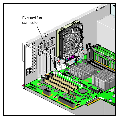
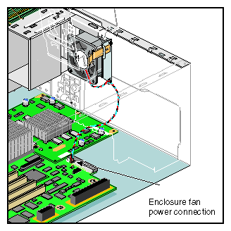
Disconnect the exhaust fan wire harness from the mother board.
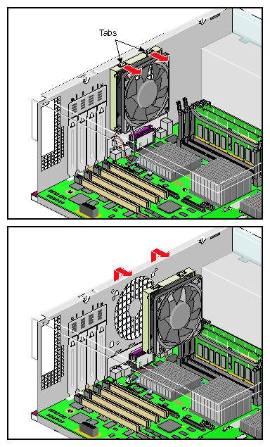
Refer to Figure 4-36.Press the two tabs on top of the fan toward the center of the enclosure. Then, slide the fan up and out of the frame and lift it clear of the enclosure. Refer to Figure 4-37.
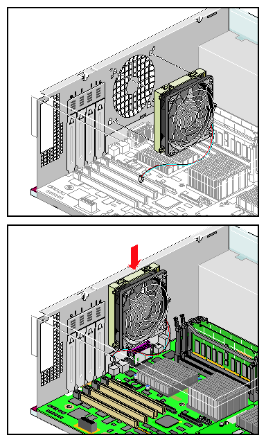
Orient the replacement fan so that the tabs are on the top edge of the fan. Then align the four pegs on the rear of the fan with the holes in the fan frame.
Insert the pegs into the holes. Then, slide the fan down into the frame until it snaps into place. Refer to Figure 4-38.
Connect the exhaust fan wire harness to the fan power connector on the system board.
Install the motherboard air duct in the enclosure. Refer to “Replacing the Motherboard Air Duct”.
Connect the SCSI and power cables to the rear of the drive(s) installed in the lower drive cage. Refer to Appendix C, “Internal Cabling Diagrams”.
Close the lower drive cage. Refer to “Closing the Lower Drive Cage”.
This completes the replacement of the exhaust fan. To return the workstation to service, refer to “Returning the Workstation to Service”.
Follow these steps to replace the hard disk drive fan:
| Note: If you have not already done so, prepare your system for service. Refer to “Preparing the Workstation for Service”. |
Remove the motherboard air duct from the system enclosure. Refer to “Replacing the Motherboard Air Duct”
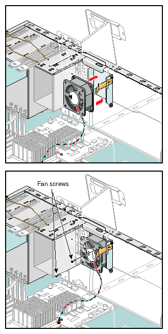
Disconnect the disk drive fan wire harness from the system board. Refer to Figure 4-39.
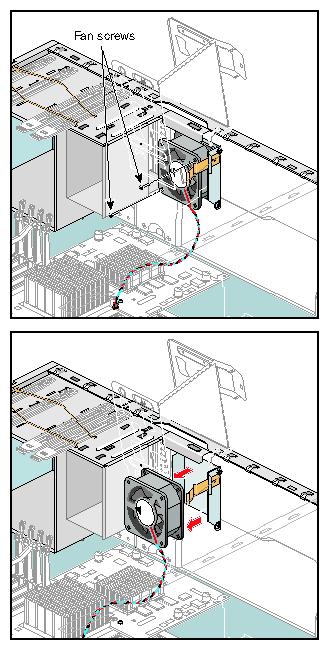
Using a short Phillips screw driver, remove the two screws that secure the disk drive fan to the fan frame. Then remove the fan from the enclosure. Refer to Figure 4-40.
Orient the replacement fan so that the airflow is toward the rear of the chassis and the wire harness is on the side closest to the power connector. Then insert the fan into the enclosure and route the wire harness through the notch in the fan frame.Refer to Figure 4-41.
Install the two Phillips screws that secure the fan to the fan frame. Then connect the disk drive fan wire harness to the power connector on the system board. Refer to Figure 4-41.
Install the motherboard air duct in the enclosure. Refer to “Replacing the Motherboard Air Duct”.
Connect the SCSI and power cables to the rear of the drive(s) installed in the lower drive cage. Refer to Appendix C, “Internal Cabling Diagrams”.
Close the lower drive cage. Refer to “Closing the Lower Drive Cage”.
This completes the replacement of the hard disk drive fan. To return the workstation to service, refer to “Returning the Workstation to Service”.
Follow these steps to replace the PCI and graphics fan housing:
| Note: If you have not already done so, prepare your system for service. Refer to “Preparing the Workstation for Service”. |
Disconnect the SCSI and power cables from any disk drives that are installed in the lower drive cage.
Remove the bezel on the front of the workstation. Refer to “Replacing the Bezel Assembly”.
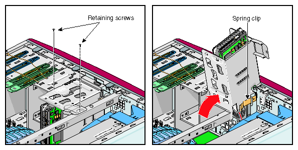
Remove the two screws that secure the lower disk drive cage to the chassis. Then, swing the drive cage up and out of the chassis until it locks into place. Refer to Figure 4-42.
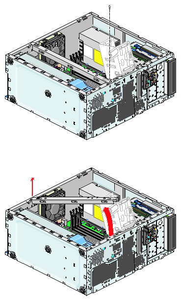
Remove the screw that secures the chassis stiffening bar to the chassis. Then, swing the chassis stiffening bar toward the rear of the chassis and remove it. Refer to Figure 4-43.
If any full length PCI boards are installed in the system, you must remove them before you replace the PCI and graphics fan housing. For instructions on removing the full-length PCI boards, refer to “Installing or Removing a PCI Board”.
Disconnect the PCI and graphics fan wire harness from the motherboard. Refer to Figure 4-44.
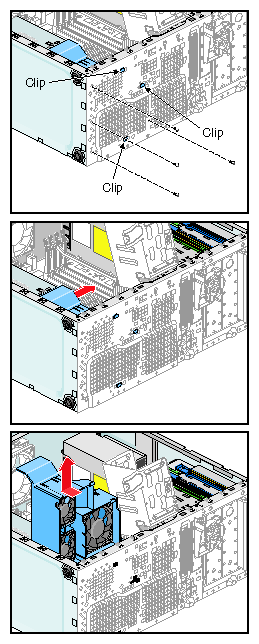
Remove the three screws that secure the housing to the front of the enclosure. Then slide the housing toward the top of the enclosure until the retention clips are aligned with the holes in the enclosure. Refer to Figure 4-44.
Pull the housing toward the center of the chassis until all of the retention clips are clear of the enclosure. Then, lift the housing up and out of the enclosure.
Lower the replacement housing into the enclosure. Then, orient the housing so that the retention clips are aligned with the holes in the front of the enclosure.
Push the housing against the front of the enclosure to seat the retention clips.
Slide the housing toward the bottom of the enclosure until the screw holes in the housing align with those in the chassis.
Install the three screws that secure the housing to the enclosure.
Connect the PCI and graphics fan wire harness to the motherboard.
If you removed any full-length PCI cards to install the housing, install them now. Refer to “Installing or Removing a PCI Board”.
Install the chassis stiffening bar. Then, install the screw that secures it to the chassis.
Connect the SCSI and power cables to the rear of the drive(s) installed in the lower drive cage. Refer to Appendix C, “Internal Cabling Diagrams”.
Close the lower drive cage. Refer to Figure 4-35.
Install the bezel on the front of the workstation. Refer to “Replacing the Bezel Assembly”.
This completes the replacement of the PCI and graphics fan housing. To return the workstation to service, refer to “Returning the Workstation to Service”.
This section provides instructions for the following procedures:
Replacing Chassis Feet
Replacing the Bezel Assembly
Replacing the Switch/LED Assembly
The four corner-mounted chassis feet on the Silicon Graphics Fuel visual workstation are self-adhesive rubber. To replace a foot, peel one off of the backing and press the adhesive side against the underside of the chassis in the desired location. Apply gentle pressure to the foot to ensure adhesion.
This section provides instructions for the following procedures:
Removing the Bezel
Installing the Bezel
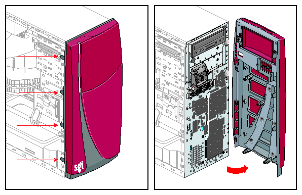
Follow these steps to remove the bezel:
Remove the side panel from the enclosure. Refer to “Preparing the Workstation for Service”.

Note: If you are only replacing the bezel, you do not need to disconnect all of the cables from the rear of the chassis or lay the chassis down. Gently pull out on the tabs that hold the left edge of the bezel to the side of the chassis. Then, swing the left edge of the bezel out and to the right, as if it were a door. Refer to Figure 4-45.
Swing the bezel to the right until it is perpendicular to the front of the chassis. The right edge of the bezel will be freed from the chassis. Lift the bezel off the chassis.
Set the bezel in a secure location.
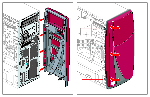
Follow these steps to install the bezel:
Align the four tabs on the right side of the bezel with the four slots on the right side of the chassis. Refer to Figure 4-46.
Swing the left edge of the bezel toward the chassis until the tabs engage on the left side of the enclosure. Refer to Figure 4-46.
Ensure that the bezel is properly seated.
Install the side panel on the enclosure. Refer to “Returning the Workstation to Service”.
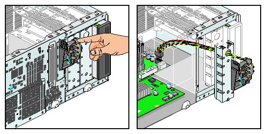
Follow these steps and refer Figure 4-47 to replace the switch/LED assembly:
Remove the bezel from the front of the enclosure. Refer to “Replacing the Bezel Assembly”.
Disconnect the switch/LED wire harness assembly from the system board.
Grasp the switch/LED assembly with one hand. Then reach into the removable media drive bay from the side of the enclosure and push out on the metal EMI shield on which the switch/LED assembly is mounted. The EMI shield and switch/LED assembly will separate from the enclosure as one piece.
Press the round retention plug out of the hole in the EMI shield. Then swing the switch/LED assembly away from the EMI shield to free the two retention clips.
Pass the switch/LED assembly wire harness through the hole in the EMI shield.
Pass the new switch/LED assembly wire harness through the EMI shield from the front side.

Note: Do not scrape the insulation on the wire harness while passing it through the hole in the EMI shield. Insert the two retention clips into their holes. Then rotate the switch/LED assembly toward the EMI shield and press the round retention plug in the hole in the EMI shield.
Install the EMI shield in the enclosure. Then connect the switch/LED assembly wire harness to the system board.
Install the bezel on the front of the enclosure. Refer to “Replacing the Bezel Assembly”.
This completes the replacement of the switch/LED assembly. To return the workstation to service, refer to “Returning the Workstation to Service”.
