Users of 3D applications typically need to change the position, orientation, and scale of objects. Users of 3D editing applications are especially in need of fine control and power in manipulating objects. Applications such as games that don't allow editing may need less control.
This chapter provides guidelines for three basic manipulation techniques: translation, rotation, and scaling, and their variations. It also discusses the special case of moving the center of rotation and scaling, which applications can optionally add to the basic techniques. It includes these topics:
Note that the focus of this chapter is manipulating complete objects; it doesn't address manipulating vertices, faces, or edges.
This section introduces the general paradigm for 3D object manipulation. It first describes the different phases of each manipulation process (for example, approach phase and drag phase) and then lists the decisions you have to make to provide a consistent user interface. It discusses these topics:
Note that because users are accustomed to manipulating objects directly, direct manipulation of 3D objects is usually preferable. In some cases, manipulating objects with the help of an intermediary like a separate dialog box can be useful, either as a secondary method or to make more precise manipulation possible. An example is a dialog box that lets users type in percentages for scaling or precise degree values for rotation.
The general paradigm for 3D object manipulation consists of several phases: manipulator display, approach, grab, drag, and release. In each of these phases, the manipulator uses certain feedback styles—neutral, locate highlight, selected, choice, and guide—to indicate the actions currently available to the user. These feedback styles are discussed in detail in “3D Manipulation Feedback”.
The phases of 3D manipulation are used throughout the rest of this chapter to illustrate how users perform the different manipulation operations. The phases can be summarized as follows:
Manipulator Display Phase. The user performs an action and the manipulator is displayed in its neutral state on the selected object. As discussed in “Selection Feedback for 3D Objects” in Chapter 14, manipulators usually appear when users select an object. Some applications may, however, require an additional step to have the manipulators appear. Silicon Graphics provides standard manipulators for translation, rotation, and scaling.
Approach phase. As the user moves the pointer over a control on the manipulator, the control changes to locate highlight style (for example, by changing color) to indicate that it's an active control that can be selected.
Grab phase. The user selects the control on the manipulator by positioning the pointer over it and pressing the left mouse button.
If the selection can result in only one action, the application provides selected feedback and, if necessary, guide feedback. For example, if the user selects a scaling handle (see Figure 15-9), the handle is displayed in the selected style and lines in the guide style appear to indicate the direction of dragging for the drag phase.
If more than one action is possible, the application provides selected feedback, choice feedback and, if necessary, guide feedback. For example, if the user selects a rotation handle (see Figure 15-6), the handle is displayed in the selected style, and two arrows in choice style are displayed to indicate that the user has to clarify the direction of the rotation. In addition, two rings appear in the guide style to indicate the direction of dragging for the drag phase.
Drag phase. The user drags the selected control to manipulate the object. During the drag, the object changes in response to the user's actions. If choice feedback was provided in the grab phase, the user has to first resolve the choice by dragging the pointer in one of the choice directions. Once the choice is made, the application replaces the choice style with the selected style to indicate the choice was made.
Release phase. The user releases the mouse button. The manipulator is returned to its original displayed state.
For translation, rotation, and scaling, use the standard manipulators provided by Silicon Graphics. If you design your own manipulator and controls for actions other than translation, rotation, and scaling, be sure to include in your design:
nonambiguous controls
precise control
nonambiguous gestures
Provide immediate feedback about available functionality of the manipulator at all times. Applications need to use consistent design schemes across manipulators and controls to provide this feedback and indicate the current state of the manipulator. Experience has shown that the following feedback styles, which use a design scheme based on colors, are useful:
Neutral. Indicates that the user isn't interacting with the controls on the manipulator. Manipulators in neutral style (often green or white) stand out from the other elements in the scene.
Locate highlight. Indicates that the pointer is over a control on the manipulator that can be selected. The control brightens (often to an orange color) as the pointer passes over it to indicate that it's a live, functional control.
Selected feedback. Indicates that the control has been selected. Controls in selected style (often rendered in yellow) stand out strongly.
Choice feedback. Indicates the user has selected a control but has to make an additional selection. For example, if the user wants to constrain translation to just one axis of a translation plane, the user first selects the plane for translation, then two arrows prompt the user to choose which of the two axes to translate along. Feedback in choice style (often rendered in orange) stands out but not as strongly as the selected style.
Guide feedback. Provides supplementary information to guide the user during object manipulation. For example, when the user chooses to rotate an object, two (or three) rings indicating the rotation sphere appear to guide the user. Feedback in the guide style (often rendered in purple) recedes but is distinct from the object and the manipulator.
In addition to the immediate feedback, continuous feedback on the state of the object is important while the user is manipulating objects. For example, as the user translates an object, the object moves in the scene in a smooth and continuous fashion so the user always knows the location of the object and can decide exactly where to position it. If the user manipulates objects in a complex scene, it may be difficult to maintain an acceptable frame rate during the manipulation, so adaptive rendering may be necessary. (See “3D Viewing Performance and Scene Fidelity” in Chapter 13 for recommended frame rates and information on adaptive rendering.)
Depending on how complex a given operation is and how often it's used, the default manipulation is either free (in all three dimensions) or constrained. Users always perform the default operations by directly interacting with the manipulator. Users perform nondefault operations by holding down a modifier key while interacting with the manipulator. Choice of a modifier key follows the guidelines outlined in Table 12-1, “Use of Modifier Keys in a 3D Application,”.
Table 15-1 provides an overview of the available manipulations and their associated modifier keys.
Table 15-1. Overview of Manipulation Techniques
Manipulation | Default? | Modifier Key |
|---|---|---|
Yes | none | |
| <Shift> | |
| <Ctrl> | |
Constrained 3D Rotation (rotation around one axis) | Yes | none |
Free 3D Rotation (rotation around a point, by default center of object) |
| <Shift> |
Yes | none | |
Uniform Scaling Around a Corner |
| <Ctrl> |
| <Shift> | |
Axial Scaling Around a Side |
| <Shift>-<Ctrl> |
Changing the Center of Rotation and Scaling Along a Plane |
| <Ctrl> |
Changing the Center of Rotation and Scaling Along an Axis |
| <Shift>-<Ctrl> |
Your application needs to provide default manipulators that are appropriate for the functional requirements of the users and for the tasks they most commonly perform. For example, if users commonly move objects through a scene but rarely scale or rotate them, only a translation manipulator is expected. If users commonly perform all three basic manipulation techniques, display translation, rotation, and scaling manipulators by default.
Once you've defined default manipulators, consider allowing users to change the set of manipulators that's displayed. At a minimum, allow users to make this change by choosing commands in the View menu. For example, if rotation is not a default manipulation but rarely used, allow users to add the rotation manipulator when they need it.
When designing a user interface for object manipulation in a 3D application...
Let users manipulate objects directly whenever possible.
If an intermediary, such as a dialog box, yields more precise results for an action and your users need precise manipulations, provide an intermediary method in addition to direct manipulation.
Provide manipulators to allow users to use direct manipulation when editing objects.
Use the standard manipulators provided by Silicon Graphics for translation, rotation, and scaling.
Make sure users can readily identify a manipulator's controls and how to interact with those controls. Also, make sure the controls allow users to precisely manipulate an object.
Provide immediate feedback on available actions during the different stages of manipulation as follows:
Display phase—Display the manipulator in its neutral state.
Approach phase—As the pointer passes over a control on the manipulator, locate highlight the control to show that it's a live, functional control.
Grab phase—Provide selected feedback if there is no additional choice to make; otherwise provide choice feedback. Provide guide feedback as appropriate to facilitate user interaction.
Drag phase—If the user was presented with a choice in the grab phase, resolve it when the user begins the drag, and replace the choice feedback with selected feedback.
Release phase—Return the manipulator to its neutral state.
Use clearly distinguishable feedback styles as follows:
Provide neutral feedback using a style that stands out from the scene; for example, use the color green or white.
Provide locate highlight for manipulator controls. That is, the controls brighten (often to an orange color) as the pointer passes over them.
Provide selected feedback using a style that stands out strongly; for example, use the color yellow.
Provide choice feedback using a style that stands out, but not as strongly as selection feedback; for example, use the color orange.
Provide guide feedback using a style that recedes but is distinct from the other styles; for example, use the color purple.
Provide continuous feedback on the status of an object while the user is manipulating it. For example, as the user translates an object, the object should move in the scene in a smooth and continuous fashion to keep the user updated on the location of the object. Use adaptive rendering if necessary.
Make commonly used and critical manipulation techniques immediately available on the manipulator via the left mouse button. Make less commonly used techniques available on a secondary level, for example, through modifier keys used in conjunction with the left mouse button.
When displaying manipulators in your 3D application...
Decide which manipulators to display by default based on the functional requirements of your users and their most common tasks.
Consider allowing users to change which subset of manipulators are currently displayed. At a minimum, allow users to specify this subset using entries in the View menu.
Translating an object means moving it and positioning it at a desired location within the scene. This section discusses and provides guidelines for the basic translation behavior users expect in 3D applications. It includes the following topics:
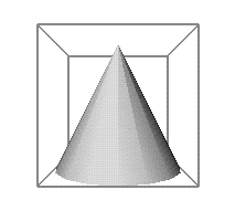
In most cases, the intuitive manipulator for translation is a bounding volume (see Figure 15-1), usually a bounding box. The bounding box defines a local coordinate space for the object and lets the user perform translation in the object's coordinate space, which may or may not be aligned with world (scene) coordinate space. See “Bounding Box Selection Feedback” for more detail on bounding boxes.
Provide access to both simple (planar) and constrained (axial) translation:
Planar translation moves objects along a 2D plane. It's discussed in detail in “Simple (Planar) 3D Translation.”
Constrained translation moves objects either:
along only one of the axes that define the plane of translation or
along the normal to these axes
Constrained translation techniques are discussed in detail in “Constrained 3D Translation.”
Note that translation in all three dimensions isn't a recommended technique and therefore isn't discussed in this guide. This is because even for experienced users, 3D translation is difficult to perform.
In the process of translating, the user could push an object so far away from the camera (along the z-axis) that it's no longer visible. While users may intend to position the object as far away as possible, they almost never want it to disappear from view. Your application should check whether users move objects beyond the vanishing point and either warn them or prevent them from doing so.
Planar translation moves objects along a 2D plane. It's the most common type of translation and is therefore the default translation behavior.
Table 15-2 illustrates user input and the resulting application behavior for planar translation:
Table 15-2. Phases of Planar Translation
Phase[a] | User Action | Application Response[b] |
|---|---|---|
User moves pointer over plane of interest. | Plane locate highlights when pointer is within its boundaries. | |
User presses and holds left mouse button while pointer is over the plane of interest. | User interface controls on the object, including other manipulators, are removed except for the bounding box (translation planes). Selected plane is displayed in selected style. Other planes of the bounding box are displayed in guide style. Standard translation feedback is displayed at the location of the pointer. Feedback consists of a perpendicular set of arrows in the selected style; the arrows represent the two main axes defining the translation plane (seeFigure 15-2). Pointer shape remains the upper left pointing arrow. | |
User drags plane of interest to translate object. | Object, bounding box (translation planes), and translation feedback (arrows) move along plane of interest based on user input (see Figure 15-2). All user input is interpreted to follow the plane of interest. As the object is translated, it's continuously displayed in its current state, using adaptive rendering if necessary (see | |
User releases mouse button to stop translation motion. | Translation feedback (arrows) disappears. The user interface controls on the object that were removed in the grab phase are redisplayed in their original state. | |
[a] See “Phases of 3D Manipulation.” [b] See “3D Manipulation Feedback.” | ||
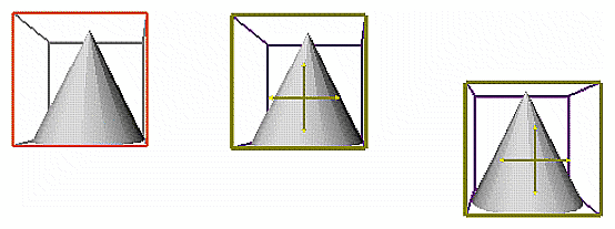
Dragging any side of the bounding box translates the object along that plane. Figure 15-2 shows translating an object to the right and down. The user has dragged the facing plane of the bounding box, enabling translation in the xy plane. Therefore, the object can move left and right as well as up and down. The object moves in the coordinate space defined by the bounding box and is independent of the scene coordinate space.
Make sure it's not possible to select through the translation planes. For example, in Figure 15-2 the left side of the bounding box, which represents the xz plane, is behind the front panel, which represents the xy plane. As the user moves the pointer over the front panel, this front xy plane locate highlights indicating that the user can select it. As the user moves the pointer over both the front xy plane and the side xz plane behind it, only the front xy plane locate highlights because the side xz panel cannot be selected through the front xy plane.
Constrained translation gives users finer control over the position of an object. The two recommended types, discussed in this section, are:
The user indicates one of these nondefault translations by holding down a modifier key while performing the standard translation action of dragging one of the translation planes in the manipulator (see “Free and Constrained 3D Manipulation”). Users expect to be able to switch from unconstrained translation to constrained translation and back at any point in the translation by pressing the appropriate modifer key, and expect to continue performing constrained translation until the modifier key is released.
Performing translation constrained to only one of the axes that define a translation plane is similar to planar translation (see Table 15-2). However, as shown in Table 15-3, the grab phase changes to allow selection of a single axis, and the drag phase has a single axis as the feedback. The user presses the <Shift> modifier key to indicate constrained translation along only one axis of the selected plane.
Table 15-3. Phases of Translation Along One Axis of the Selected Plane
Phase | User Action | Application Response |
|---|---|---|
Same as for planar translation (see Table 15-2). | Same as for planar translation. | |
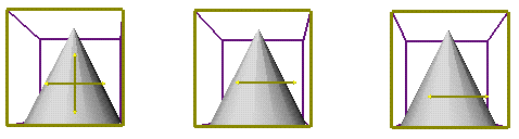
User presses and holds the <Shift> key and left mouse button while pointer is over plane of interest. | Same as for planar translation with this exception: Translation feedback is displayed in the choice style (see Figure 15-3). | |
Drag | User continues to press the <Shift> key and drags in the direction of one of the two choice arrows to identify the desired translation axis. | When the user has moved the pointer far enough to clearly indicate the axis for translation, the arrow representing that axis changes to selected style and the other arrow disappears (see Figure 15-3). Remainder of this phase is the same as for planar translation with this exception: translation is along the selected axis, not along the selected plane, so all user input is interpreted to follow the selected axis. |
Same as for planar translation. | Same as for planar translation. |
Figure 15-3 illustrates this type of constrained translation. The user simultaneously presses the <Shift> key and the left mouse button. In response, the application displays the translation feedback arrows in choice style. The user then selects one of the two axes indicated by these choice arrows. After the user has dragged slightly to the right, only the arrow representing the user's choice of the left-right axis (x) remains, and translation is restricted to this axis until the user releases the <Shift> key.
Users want to perform translation along a path perpendicular to a plane primarily for these two reasons:
Other planes of the bounding box that are orthogonal to the current plane aren't always visible or accessible.
Some users need to rapidly translate objects along all three axes.
Performing translation constrained to the axis that's normal to the selected translation plane is similar to planar translation (see Table 15-2). However, as shown in Table 15-4, the grab phase changes to show the axis that's normal to the selected plane, and the drag phase translates the object along this normal axis. The user presses the <Ctrl> modifier key to indicate translation constrained along the normal.
Table 15-4. Phases of Translation Along the Normal to the Selected Plane
Phase | User Action | Application Response |
|---|---|---|
Same as for planar translation. (see Table 15-2). | Same as for planar translation. | |
Grab | User presses and holds <Ctrl> key and left mouse button while pointer is over plane of interest. | Same as for planar translation with this exception: Translation feedback consists of an arrow representing the normal to the selected plane and a small pair of axes representing the main axes of the selected translation plane (see Figure 15-4). This feedback is displayed in selected style. |
Drag | User continues to press <Ctrl> key and drags plane of interest to translate object. | Same as for planar translation except that object, bounding box (translation planes), and translation feedback (axes and arrow) move along the normal to plane of interest (see Figure 15-4), so all user input is interpreted to follow this normal. |
Same as for planar translation. | Same as for planar translation. |
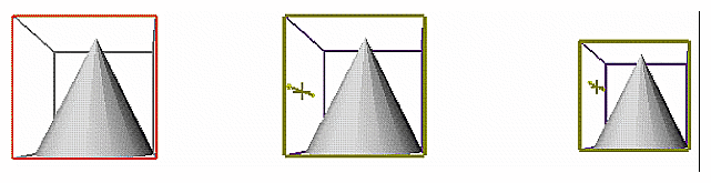
Figure 15-4 shows this type of constrained translation. The user simultaneously presses the <Ctrl> key and the left mouse button. In response, the application displays the translation feedback arrow and axes in the selected style. As the user drags the frontmost plane of the bounding box in this example (the xy plane), translation is restricted to the axis normal to this selected plane (z) until the user releases the <Ctrl> key.
When designing a user interface for 3D translation...
Use the standard translation manipulator either alone or in combination with the other standard manipulators. This manipulator is a set of translation planes arranged to define a bounding box around the object.
Allow users to perform translation in the planes of the object's bounding box. These planes may or may not be aligned with the world (scene) coordinate space.
Don't allow users to translate objects that are part of a scene into unusable locations, such as behind the camera or so far back along the z axis that they vanish from view.
Provide planar translation as the default translation method (see Table 15-2).
Provide access to constrained translation along only one axis of a plane (see Table 15-3).
Provide access to axial (constrained) translation along the normal to a plane (see Table 15-4).
Allow users to switch from planar translation to constrained translation and back at any point in a translation. For example, if the user is performing planar translation by dragging a translation plane and then presses the <Shift> key, switch to axial translation along the plane until the <Shift> key is released.
Display the appropriate translation feedback as the user switches between unconstrained and constrained translation.
Don't allow users to select objects or controls through the translation planes.
Rotating an object means turning it around an axis or around a point. Rotating objects is important in most 3D applications because users need access to all sides of the object. This section discusses and provides guidelines for the basic rotation behavior users expect in 3D applications. It discusses these topics:
Some applications may also find it useful to allow users to change the center of rotation. This is discussed in “Changing the Center of Rotation and Scaling for 3D Objects”.
Provide access to both constrained rotation and free rotation in your application; both are critical in providing users access to rotation functionality:
Constrained rotation is rotation around an axis. Because free rotation makes the object difficult to control, constrained rotation is the appropriate default behavior. It's discussed in “Constrained 3D Rotation.”
Free rotation is rotation around a point. It's discussed in “Free 3D Rotation.”
When users rotate an object, the default center of rotation for free rotation is the center of the object itself (the center of the object's bounding box); for constrained rotation, it's an axis that runs through the center of the object. There are situations where users need to change the center of rotation; see “Changing the Center of Rotation and Scaling for 3D Objects” for a detailed discussion of this special case.
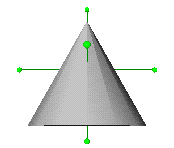
The standard rotation manipulator, shown in Figure 15-5, is a set of rotation handles, at most one per side, that emanate from the object's center of rotation. The length of each handle is the length of the bounding box plus one-eighth of it on each side.
Constrained rotation is rotation around an axis. Because it's much easier to control than free rotation, it's the default rotation behavior. Table 15-5 illustrates user input and the resulting application behavior for constrained rotation.
Table 15-5. Phases of Constrained Rotation
Phase[a] | User Action | Application Response[b] |
|---|---|---|
User moves pointer over a rotation handle. | Rotation handle of interest locate highlights. | |
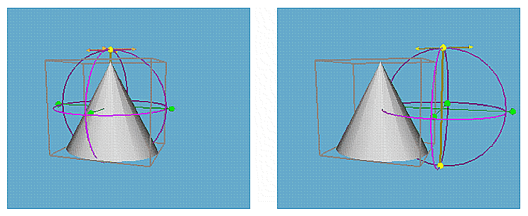
User presses and holds left mouse button while pointer is over rotation handle of interest. | User interface controls on the object, including other manipulators, are removed except for rotation handles. Rotation handle of interest is displayed in selected style, and other handles are displayed in neutral style. Standard rotation feedback is displayed at the location of the selected handle. Feedback consists of a perpendicular set of arrows in the choice style and two rings in guide style to indicate available rotation directions (seeFigure 15-6). Pointer shape remains the upper left pointing arrow. | |
User drags rotation handle to rotate object around the selected axis. | When user has moved the pointer far enough to clearly indicate direction and axis for rotation, the corresponding arrow changes to selected style, and the other arrow and its associated guide ring disappear (see Figure 15-6). Object, rotation handles, and rotation feedback (ring and arrow) rotate around the selected axis based on user input. All user input is interpreted to follow the ring. As the object is rotated, it's continuously displayed in its current state, using adaptive rendering if necessary (see | |
User releases mouse button to stop rotation motion. | Rotation feedback (arrow and ring) disappears. User interface controls on object that were removed in grab phase are redisplayed in their original state. | |
[a] See “Phases of 3D Manipulation.” [b] See “3D Manipulation Feedback.” | ||
Figure 15-6 shows the sequence of events for constrained rotation. When the user grabs a rotation handle, the rotation feedback appears indicating that the user must choose one of two axes for the rotation. The user chooses a direction and an axis for rotation by dragging along one of the two arrows. Once the axis has been chosen, all user input is interpreted to rotate the object around the selected axis in the given direction.
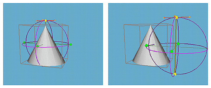
In free rotation, the object rotates around a point rather than an axis; that is, the object can rotate around all three axes simultaneously. Typically, the default center of rotation is at the center of the object's bounding box. The user presses the <Shift> modifier key to indicate free rotation.
Free rotation is similar to constrained rotation (see Table 15-5). However, as shown in Table 15-6, the grab phase displays a virtual trackball as the rotation feedback, and the drag phase rotates the object around the center of rotation.
Table 15-6. Phases of Free Rotation
Phase | User Action | Application Response |
|---|---|---|
Same as for constrained rotation (see Table 15-5). | Same as for constrained rotation. | |
User presses and holds <Shift> key and left mouse button while pointer is over rotation handle of interest. | Same as for constrained rotation with this exception: Rotation feedback consists of three rings representing a virtual trackball (see Figure 15-7). This feedback is displayed in guide style. No choice arrows are provided. | |
User continues to press <Shift> key and drags rotation handle to rotate object simultaneously in all three dimensions around the center of rotation. | Same as for constrained rotation except that object, rotation handles, and rotation feedback (three rings) rotate around the center of rotation (see Figure 15-7). All user input is interpreted to follow the virtual trackball. | |
Same as for constrained rotation. | Same as for constrained rotation. |
Figure 15-7 illustrates free rotation. The user simultaneously presses the <Shift> key and the left mouse button. In response, the application displays the virtual trackball rotation feedback. As the user drags the pointer, the object is rotated around the point at the center of the virtual trackball.
Users expect to be able to switch between free rotation and constrained rotation at any time during a rotation operation:
If the user is performing constrained rotation, pressing the <Shift> key immediately puts the object into free rotation. The pointer starts following a virtual trackball path.
If the user is performing free rotation, releasing the <Shift> key immediately puts the object into constrained rotation. The object rotates around the axis the pointer is moving around.
Users can continually press and release the <Shift> key to switch to and from free rotation as long as they continue to press the left mouse button while the pointer is over a rotation handle.
When designing a user interface for 3D rotation...
Use the standard rotation manipulator either alone or in combination with the other standard manipulators. This manipulator is a set of handles that emanate from the center of rotation. Typically, the default center of rotation is the center of the object (the center of the object's bounding box).
Provide constrained rotation around an axis as the default rotation method (see Table 15-5).
Provide access to free rotation around a point (see Table 15-6).
Allow users to switch between constrained and free rotation at any point in a rotation. For example, if the user is performing constrained rotation by dragging along a ring and then presses the <Shift> key, switch to free rotation and interpret pointer movements as following the virtual trackball until the <Shift> key is released.
As the user switches between constrained and free rotation, display the appropriate rotation feedback. For example, if the user is performing free rotation and then releases the <Shift> key, switch to constrained rotation and display the appropriate rotation feedback. Determine the direction and axis for rotation based on the next pointer movement. Once the direction and axis have been determined, display the appropriate arrow and ring feedback for this direction and remove the virtual trackball.
Scaling an object means enlarging or reducing it without changing its position or orientation. This section discusses and provides guidelines for the basic scaling behavior users expect in 3D applications. It includes these topics:
Some applications may find it useful to allow users to change the center of scaling. This is discussed in “Changing the Center of Rotation and Scaling for 3D Objects.”
There are two scaling operations, uniform scaling and axial scaling:
Uniform scaling preserves proportions, and is the most common type of scaling so it's the default scaling behavior. Uniform scaling is discussed in detail in “Uniform 3D Scaling”.
In axial scaling (also referred to as stretching), the object is scaled or stretched in only one of the three dimensions at a time. Because axial scaling is less commonly used than uniform scaling, it's the non-default scaling operation. Axial scaling is discussed in detail in “Axial 3D Scaling (Stretching).”
Objects are scaled with respect to a fixed anchor point, which is, by default, the center of the object (the center of the object's bounding box). Users also need to occasionally scale an object around a corner or side of the object's bounding box, as discussed in “Scaling Around the Opposite Corner or Side.” Some applications may find it necessary to allow users to change the center of scaling. This is discussed in “Changing the Center of Rotation and Scaling for 3D Objects.”
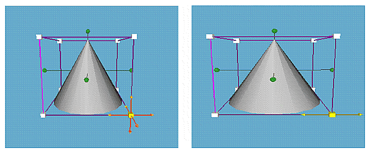
The standard scaling manipulator, shown in Figure 15-8, is a set of cube-shaped handles located at the vertices of the object's bounding box. To scale an object, the user drags one of these cube-shaped handles. Dragging toward the center of scaling shrinks the object, dragging away from the center of scaling enlarges the object.
Uniform scaling preserves proportions; that is, all axes of the object are uniformly enlarged or reduced during the operation. It's the most common type of scaling so it's the default scaling behavior. Typically, the default center of scaling is at the center of the object (the center of the object's bounding box). Table 15-7 illustrates user input and the resulting application behavior for uniform scaling.
Table 15-7. Phases of Uniform Scaling
Phase[a] | User Action | Application Response[b] |
|---|---|---|
User moves pointer over a scaling handle. | Scaling handle of interest locate highlights. | |
User presses and holds left mouse button while pointer is over scaling handle of interest. | User interface controls on the object, including other manipulators, are removed except for the scaling handles. Scaling handle of interest is displayed in selected style. Other handles are displayed in neutral style. Standard scaling feedback is displayed: a set of arrows in guide style that emanate from the center of scaling and go through each of the scaling handles and rotation handles displayed in neutral style (seeFigure 15-9). The rotation handles provide feedback on the current location of the center of rotation and scaling. Pointer shape remains the upper left pointing arrow. | |
User drags scaling handle to scale object in all three dimensions around center of scaling. | Object, scaling handles, and scaling feedback are uniformly scaled in all three dimensions around the center of scaling based on user input (see Figure 15-9). All user input is interpreted to move either closer to or farther away from the center of scaling. As the user drags closer to the center of scaling, object, scaling handles, and scaling feedback shrink. As the user drags farther away from the center of scaling, the object, and so on, are enlarged. As the object is scaled it's continuously displayed in its current state, using adaptive rendering if necessary (see | |
User releases mouse button to stop scaling. | Scaling feedback consisting of guide arrows and rotation handles disappears. User interface controls on the object that were removed in the grab phase are redisplayed in their original state. | |
[a] See “Phases of 3D Manipulation.” [b] See “3D Manipulation Feedback.” | ||
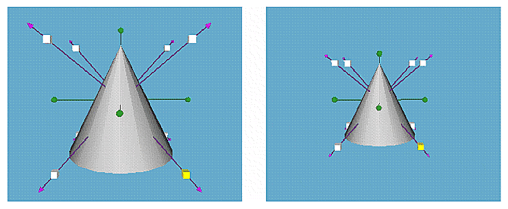
Figure 15-9 shows the sequence of events for uniform scaling. When the user grabs the scaling handle, scaling feedback is displayed. It serves as a guide to the user in dragging to make the object smaller or larger. As the user drags the pointer toward the center of scaling, the object shrinks uniformly in all three dimensions.
In addition to uniform scaling, users expect to be able to perform axial scaling (stretching) where the object is scaled or stretched in only one of the three dimensions at a time. Axial scaling is similar to uniform scaling (see Table 15-7). However, as shown in Table 15-8, the grab phase changes to allow selection of a single dimension (axis) for scaling, and the drag phase scales the object only along this single dimension. The user presses the <Shift> modifier key to indicate axial scaling.
Table 15-8. Phases of Axial Scaling (Stretching)
Phase | User Action | Application Response |
|---|---|---|
Same as for uniform scaling (see Table 15-7). | Same as for uniform scaling. | |
User presses and holds <Shift> key and left mouse button while pointer is over the scaling handle of interest. | Same as for uniform scaling with this exception: Scaling feedback consists of the object's bounding box displayed in guide style, and three arrows emanating from the selected scaling handle that represent the three possible axes (dimensions) for stretching (see Figure 15-10). Arrows are displayed in choice style at the location of the selected handle. Feedback also includes rotation handles in neutral style, which provide feedback on the current location of the center of rotation and scaling. (Rotation handles are also part of scaling feedback for uniform scaling.) | |
User continues to press <Shift> key and drags scaling handle in the direction of one of the three choice arrows to identify the desired scaling dimension. After the user makes this choice, further dragging scales the object along this single axis. | When user has moved pointer far enough to clearly indicate the axis (dimension) for scaling, the arrow representing this axis changes to selected style and the other two arrows disappear (see Figure 15-10). The remainder of this phase is the same as for uniform scaling with this exception: Scaling is along the selected dimension, not uniformly along all three dimensions. All user input is interpreted to enlarge or shrink the object along the selected dimension. | |
Release | Same as for uniform scaling. | Same as for uniform scaling. |
Figure 15-10 illustrates axial scaling. The user simultaneously presses the <Shift> key and the left mouse button. In response, the application displays the bounding box and choice arrows for axial scaling. As the user drags the pointer, the x axis is selected for scaling. As the user drags the pointer farther away from the center of scaling, the object is enlarged along this single dimension.
Users expect to be able to switch between uniform scaling and axial scaling at any time during a scaling operation:
If the user is performing uniform scaling and presses the <Shift> key, the application immediately prompts the user to choose a dimension for axial scaling. Once the dimension (axis) has been selected, dragging scales the object only along this single dimension.
If the user is performing axial scaling and releases the <Shift> key, the application immediately allows the user to uniformly scale the object. Dragging scales the object uniformly along all three dimensions.
Users can continually press and release the <Shift> key to switch between uniform and axial scaling as long as they continue pressing the left mouse button while the pointer is over a scaling handle.
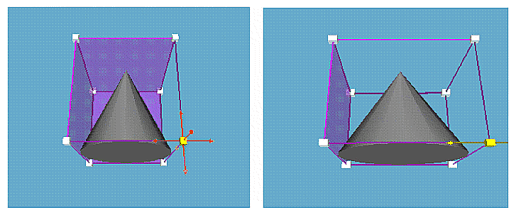
Users occasionally want to scale an object around a specific corner (scaling handle) for uniform scaling and around a specific plane for axial scaling. To indicate this alternate behavior for scaling, the user presses the <Ctrl> modifier key.
Table 15-9 illustrates user input and resulting application behavior for uniform scaling around a corner. Note that it's similar to uniform scaling around the center of scaling (see Table 15-7).
Table 15-9. Phases of Uniform Scaling Around a Corner
Phase | User Action | Application Response |
|---|---|---|
Same as for uniform scaling (see Table 15-7). | Same as for uniform scaling. | |
User presses and holds <Ctrl> key and left mouse button while pointer is over scaling handle of interest. | Same as for uniform scaling with these exceptions: The set of arrows in the guide style emanate from the scaling handle directly opposite the selected handle (Figure 15-11). Rotation handles aren't shown because scaling isn't around the center of rotation and scaling. | |
User continues to press <Ctrl> key and drags scaling handle to scale object in all three dimensions around the corner opposite the selected handle. | Same as for uniform scaling with this exception: Scaling is done around the handle opposite the selected handle, not around the center of scaling (see Figure 15-11). | |
Release | Same as for uniform scaling. | Same as for uniform scaling. |
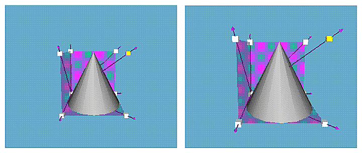
Table 15-10 illustrates the same information for axial scaling around a specific side of the object's bounding box. Note that this is similar to axial scaling around the center of scaling (see Table 15-8).
Table 15-10. Phases of Axial Scaling Around a Side
Phase | User Action | Application Response |
|---|---|---|
Same as for axial scaling (see Table 15-8). | Same as for axial scaling. | |
User presses and holds <Ctrl> and <Shift> keys and left mouse button while pointer is over the scaling handle of interest. | Same as for axial scaling with this exception: Rotation handles aren't shown because scaling isn't around the center of rotation and scaling (see Figure 15-12). | |
User continues to press <Ctrl> and <Shift> keys and drags scaling handle to indicate the desired scaling dimension. After the user makes this choice, further dragging scales object in this dimension around the plane normal to the selected axis and on the opposite side of the bounding box from the selected handle. | Same as for axial scaling with this exception: Scaling occurs around the side of the bounding box that's normal to the selected axis and on the opposite side of the bounding box from the selected handle (see Figure 15-12). | |
Release | Same as for axial scaling. | Same as for axial scaling. |
When performing uniform or axial scaling, users expect to be able to change the point of scaling to the opposite corner or opposite side at any point during a scaling operation:
If the user is performing uniform scaling, pressing the <Ctrl> key immediately starts uniformly scaling the object around the corner opposite to the selected handle. Releasing the <Ctrl> key immediately returns to uniform scaling around the center of scaling.
If the user is performing axial scaling, pressing the <Ctrl> key immediately starts scaling the object around the plane normal to the selected axis and on the opposite side of the bounding box from the selected handle. Releasing the <Ctrl> key immediately returns to axial scaling around the center of scaling.
Users can continually press and release the <Ctrl> key to switch between scaling around a corner or side and scaling around the center of scaling as long as they continue pressing the left mouse button while the pointer is over a scaling handle.
When designing a user interface for 3D scaling...
Use the standard scaling manipulator either alone or in combination with the other standard manipulators. The manipulator consists of cube-shaped handles at the vertices of the bounding box.
Scale objects around the center of scaling. Typically this is the center of the object (the center of the object's bounding box).
Provide uniform scaling as the default scaling method (see Table 15-7).
Provide access to axial scaling (stretching) as defined in Table 15-8.
Allow the user to switch between uniform and axial scaling at any point in a scaling operation. For example, if the user is performing axial scaling, then releases the <Shift> key, switch to uniform scaling.
As the user switches between uniform and axial scaling, display the appropriate scaling feedback. For example, if the user is performing uniform scaling, then presses the <Shift> key, switch to axial scaling and display the appropriate scaling feedback. Determine the single axis for stretching based on the next pointer movement. Once this axis has been determined, remove the two axes that were not selected and display the selected axis until the <Shift> key is released.
Allow users to perform uniform scaling around a specific corner as an alternative to scaling around the center of scaling (see Table 15-9).
Allow users to perform axial scaling around a specific side of the object's bounding box as an alternative to axial scaling around the center of scaling (see Table 15-10).
Allow the user to switch between scaling around a corner or side and scaling around the center of scaling at any time during a scaling operation. For example, if the user is performing uniform scaling around the center of scaling, then presses the <Ctrl> key, switch to scaling around the corner opposite to the selected handle.
As the user switches between scaling around a corner or side and scaling around the center of scaling, display the appropriate feedback. For example, if the user is performing uniform scaling around a corner, then releases the <Ctrl> key, switch to scaling around the center of scaling and display the appropriate guide feedback for this type of scaling.
At times, users may want to explicitly choose a center for rotation or scaling. For example, you have a graphic object that's a stick figure. An arm is part of the stick figure; its natural centers of rotation are the elbow and the wrists, not the center of the arm.
Typically, the center of rotation and the center of scaling are defined to be the same point. Table 15-11 illustrates user input and the resulting application behavior for changing the center of rotation (along a plane). The user presses the <Ctrl> key while dragging on a rotation handle to change this point. Note that for the standard manipulators recommended by Silicon Graphics, a change in the center of rotation also changes the center of scaling. If your users need to have separate centers of rotation and scaling, you need to provide a separate mechanism for changing the center of scaling.
Table 15-11. Phases of Changing the Center of Rotation and Scaling Along a Plane
Phase[a] | User Action | Application Response[b] |
|---|---|---|
Approach | User moves pointer over a rotation handle. | Rotation handle of interest locate highlights. |
Grab | User presses and holds <Ctrl> key and left mouse button while pointer is over rotation handle. | User interface controls on the object, including other manipulators, are removed except for rotation handles. Rotation handle of interest is displayed in selected style. Other handles are displayed in neutral style. Feedback is displayed at the location of the selected handle. Feedback consists of a perpendicular set of arrows in selected style representing the two axes of the plane in which the user can move the point of rotation, and three rings in guide style representing a virtual trackball around the center of rotation (seeFigure 15-13). In addition, the object's bounding box is displayed in neutral style to further guide the user in placing the center of rotation. Pointer shape remains upper left pointing arrow. |
Drag | User continues to press <Ctrl> key and drags rotation handle to move center of rotation and scaling along selected plane. | Feedback assembly (two arrows and three rings), rotation handles, and center of rotation and scaling move along plane based on user input. All input is interpreted to follow the plane represented by the two arrows. Object and bounding box don't move. |
Release | User releases mouse button to stop movement of the center of rotation and scaling. | Feedback consisting of the arrows, rings, and bounding box disappears, and the user interface controls on the object that were removed in the grab phase are again displayed in their original state. |
[a] See “Phases of 3D Manipulation.” [b] See “3D Manipulation Feedback.” | ||
In addition to moving the center of rotation and scaling along a plane, users may want to constrain the movement to a single axis. This is similar to moving the center along a plane (see Table 15-11). However, as shown in Table 15-12, the grab phase changes to indicate that the user must choose an axis for movement, and the drag phase changes to restrict movement to the selected axis. The user presses the <Ctrl> key while dragging on a rotation handle to change the center of rotation and scaling and also presses the <Shift> key to constrain this movement to a single axis of the plane.
Table 15-12. Phases of Changing the Center of Rotation and Scaling Along an Axis
Phase | User Action | Application Response |
|---|---|---|
Approach | User moves pointer over a rotation handle. | Same as for changing center of rotation and scaling along a plane (see Table 15-11). |
Grab | User presses and holds <Shift> and <Ctrl> keys and left mouse button while pointer is over rotation handle. | Same as for changing center of rotation and scaling along a plane with this exception: The perpendicular arrows included in the feedback are displayed in choice style indicating that user must choose an axis for movement (see Figure 15-14). |
Drag | User continues to press <Shift> and <Ctrl> keys and drags rotation handle to move center of rotation and scaling along selected axis. | When user has moved the pointer far enough to clearly indicate the axis for movement, arrow representing this axis changes to selected style and the other arrow disappears (see Figure 15-14). The remainder of this phase is the same as for changing the center of rotation and scaling along a plane with this exception: Movement is restricted to the selected axis. All user input is interpreted to follow it. |
Release | User releases mouse button to stop movement of the center of rotation and scaling. | Same as for changing the center of rotation and scaling along a plane. |
When users are interacting with a rotation handle, they expect at any point to be able to switch among constrained rotation, free rotation, changing the point of rotation along a plane, and changing the point of rotation along an axis.
When designing a user interface for changing the center of rotation and scaling...
If necessary, allow users to change the center of rotation and scaling using the standard rotation manipulator.
As users move the center of rotation and scaling, make sure that they can always identify the current center.
Allow users to change the center of rotation and scaling along a plane (see Table 15-11).
Allow users to change the center of rotation and scaling along an axis (see Table 15-12).
At any time while dragging a rotation handle, allow users to switch among constrained rotation, free rotation, changing the center of rotation and scaling along a plane, and changing the center of rotation and scaling along an axis. For example, if the user is performing constrained rotation then presses the <Ctrl> and <Shift> keys, switch to changing the center of rotation and scaling along an axis.
As the user switches among constrained rotation, free rotation, changing the center of rotation and scaling along a plane, and changing the center of rotation and scaling along an axis, display the appropriate feedback. For example, if the user is moving the center of rotation and scaling along a plane then presses the <Shift> key, switch to moving this center along an axis and display the appropriate feedback. Determine the single axis for movement based on the next pointer movement. Once this axis has been determined, remove the axis that wasn't selected and display the selected axis until the <Shift> key is released.
When the current selection consists of more than one object, the standard manipulations of translation, rotation, and scaling affect the selected objects somewhat differently than if each object was manipulated by itself. To perform these manipulations, one of the objects in the selection is assigned as the “key” object; manipulations on all of the objects in the selection are done with respect to the manipulation controls of the key object. For example, all selected objects are translated along the selected plane of the key object.
If your application supports the concept of a lead object and uses the manipulator as the selection feedback only on this object as described in “Manipulator Selection Feedback” in Chapter 14, the lead object is always also the key object because it's the only object displaying the manipulators. Otherwise, the key object is the one that the user is currently interacting with via its manipulators.
The remainder of this section discusses the specific manipulations as follows:
When users perform translation on a selection consisting of several objects, all selected objects move in the selected translation plane of the key object, regardless of their own orientations. The relative positional relationships of the selected objects don't change as a result of translation. The same behavior applies to constrained translation and translation along the normal. That is, translation is done with respect to the selected axis of the key object.
Translation of a single object is discussed in detail in “Translating 3D Objects.”
When the user selects more than one object and starts a rotation operation, all selected objects rotate around the center of rotation for the key object.
Rotation of a single object is discussed in detail in “Rotating 3D Objects.”
When the user selects more than one object and starts a uniform scaling operation, all objects scale proportionally with the key object and scale about the same center of scaling as the key object.
Axial scaling (stretching) is treated quite differently when the user selects more than one object. In this case, only the key object is scaled; other selected objects don't change. While this may seem like an inconsistency in light of applying other manipulations to all selected objects, it's the safest default approach. Applying stretching to objects that are not aligned with the master object can lead to shearing, which is an undesirable outcome.
When users manipulate more than one object at a time...
Assign one object as the key object for the manipulations. Typically, only the lead object displays the manipulators so this object is by default the key object. If your application instead displays manipulators on all selected objects, the object associated with the manipulator the user is currently interacting with is the key object.
For translation, translate all selected objects along the chosen translation plane for the key object, regardless of the orientation of the other selected objects. Don't change the relative positional relationships of the selected objects.
For rotation, rotate all selected objects around the center of rotation for the key object.
For uniform scaling, scale all selected objects the same amount as the key object and about the same center of scaling as the key object.
For axial scaling (stretching), scale only the key object (the object being manipulated) rather than all selected objects. This prevents shearing of objects that are not aligned with the key object.