Interactive viewing must be supported in the user interface of all 3D applications, even if those applications don't support editing.
Viewing 3D content is more complex than viewing a 2D image because of the added dimension. This added dimension means not only that there is more to look at, but also that there are more ways of looking at things. For example, users may want to view the sides, back, and top of a 3D model of a computer, walk through a virtual room, or fly through a 3D landscape. Interface designers have to determine the appropriate viewing functionality for their application and implement it in a consistent and intuitive way.
This chapter discusses interactive viewing of 3D objects in these sections:
“Introduction to 3D Viewing” provides an introduction to the viewing paradigm and discusses some terminology.
“3D Viewing Functions” introduces inspection and navigation, which are two different viewing modes, and describes the viewing functions an application needs to support in each mode.
“3D Viewing Interface Trade-Offs” discusses 3D application design issues that developers typically must address and provides recommendations for resolving these issues.
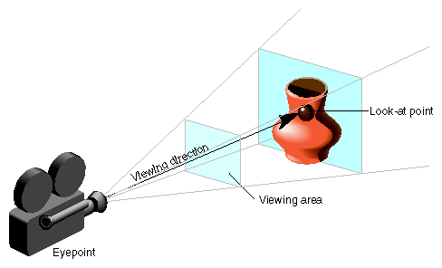
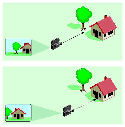
3D viewing can be thought of as using a camera to view the world. The following concepts are used in this document to describe the user interface to viewing functions (see Figure 13-1):
Eyepoint. The eyepoint is the position of the user's eye. The camera is always positioned at the eyepoint. As the user moves the location of the camera, the location of the eyepoint also changes.
Viewing area. The viewing area is what the user can currently see while looking through the camera. It's what the user sees in the application's viewport.
Viewing direction. The viewing direction refers to how the camera is oriented in space. As the user turns the camera to the left or right or tilts the camera up or down, the viewing direction changes accordingly. As the user changes the viewing direction, the contents of the viewing area also changes. In effect, the user is looking through the camera at a different part of the scene.
Look-at point. The look-at point is the current center of interest within the scene. The camera's viewing direction is always aimed so that the look-at point is in the center of the viewing area.
In the context of this document, viewing refers to manipulating a camera to view the contents of a 3D application (see “Introduction to 3D Viewing”). This document distinguishes between the two basic viewing modes, inspection and navigation. Every 3D application needs to support at least one; if your application supports both, pick one as the primary mode.
Although viewing refers to manipulating a camera in a 3D application, users may base their interaction with the application on a different metaphor. These fundamental metaphors are also discussed in the following sections. For example, during inspection users interact with the scene (or object) they are viewing as if it were a single object that they are holding in their hand. They expect to be able to move this scene (or object) around in space (see “3D Viewing Trade-Offs and Related Guidelines”). Application developers, on the other hand, find it useful to implement the inspection functions in terms of a camera that moves around the scene being viewed. It's important that your application allows users to work with viewing functions using the metaphors they expect regardless of how the application implements them.
This section describes the different functions available in inspection and in navigation. Table 13-1 provides an overview of each function, the mouse and key bindings used to access it, and the pointer shape displayed when the user is accessing it. Each function is discussed in detail in the following sections.
Table 13-1. 3D Viewing Functions and User Interface
Function | View Mode | Pointer | Mouse and Keyboard Binding | |
|---|---|---|---|---|
Inspection
(default) | Dragging with the left mouse button. | |||
Inspection
| Dragging while simultaneously pressing the left and middle mouse buttons. | |||
Inspection | Dragging with the middle mouse button. | |||
Navigation
(default) | Dragging with the left mouse button. | |||
Navigation | Dragging while simultaneously pressing the left and middle mouse buttons. | |||
Navigation | Dragging with the middle mouse button. | |||
Inspection and Navigation | Clicking with the left mouse button.[a] | |||
[a] Many applications need to reserve clicking with the left mouse button for a more useful function (for example, activating a link or initiating object behavior). In those applications, allow users to first activate a seek tool, then click in the scene with the left mouse button to seek. | ||||
This section first gives an overview of inspection, then describes three viewing functions that apply only to inspection (and not to navigation):
The section also discusses “Seeking,” which has the same effect in both inspection and navigation.
Each function is first presented from the user's point of view, then discussed in terms of the implementation model.
Inspection is an approach to viewing where users can examine a scene as if it's a single object they are holding in their hand. For example, users may want to examine the model of a coffee mug the same way they would examine a real mug by holding it and turning it around.
The expected user model for inspection is that users are manipulating the scene, not the camera. From the users' perspective, all inspection controls appear to manipulate the scene (or object) while the camera remains stationary. For example:
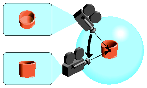
Pressing the left mouse button and dragging the pointer down (tumbling) rotates the object towards the user. To achieve this, the application actually moves the camera up over the object (see Figure 13-2).
Pressing the middle mouse button and dragging the pointer to the left (panning) moves the scene toward the left of the viewing window. To achieve this, the application moves the camera to the right (see Figure 13-5).
Note that in both examples, users move the control (and pointer) in the direction they want the scene (or object) to move. To achieve this, the application moves the camera in the opposite direction of the control (and pointer).
Table 13-2 provides an overview of the different functions available in inspection.
Table 13-2. Overview of Inspection Viewing Functions
Function | User Model | Implementation Model |
|---|---|---|
User holds object and rotates it to view it from all sides and angles. | Camera (eyepoint) moves around a fixed look-at point on a spherical course. Camera moves opposite to direction of user's action. | |
User moves object closer or farther away. | Camera (eyepoint) moves toward a fixed look-at point to move object closer and moves away from look-at point to move object farther away. Viewing direction remains unchanged. | |
User moves object up, down, left, or right in viewing window. | Camera (eyepoint) moves in plane perpendicular to viewing direction. Camera moves opposite to movement of object. Viewing direction is unchanged. Look-at point moves with camera. | |
User selects object (or part of object). Selected object is centered in viewing window and moved closer to user with each click. | Look-at point moves to where user clicked in the scene. Camera (eyepoint) turns so that look-at point is centered in viewing window. Camera moves closer by half the original distance between camera and object. |
Tumbling is the default viewing function for inspection. Users rotate a model of an object or a scene as if they were holding it in their hand. Users expect to be able to tumble the object in all three dimensions around the fixed look-at point. Tumbling doesn't change the location of the object in space.
The user controls tumbling by dragging with the left mouse button. The movement follows a virtual trackball imposed on the viewing window. The initial position of the pointer on this virtual trackball influences the tumbling behavior: If the user positions the pointer in the center of the viewing window (trackball) and drags horizontally (or vertically), the object tumbles around the y axis (or x axis). If the user positions the pointer in the center of the viewing window and drags out in any direction, the object tumbles around an axis perpendicular to the drag. If the user drags in a circle around the center of the virtual trackball, the object tumbles around the z axis. If the user drags beyond the limits of the trackball, the object continues to tumble until the user releases the mouse button.
Figure 13-2 illustrates tumbling from the implementation perspective. The camera (eyepoint) moves around the scene as though the camera were placed on the surface of a sphere. The look-at point remains stationary at the center of the sphere. The camera moves opposite to the direction of the rotation. Using the original camera position, the user can look into the pot but can't see much of the pot's outside surface. After the user has tumbled the bottom of the pot upwards, it's possible to see the pot's surface. To accomplish this rotation, the eyepoint (camera) moves down along the surface of the sphere and the look-at point remains stationary.
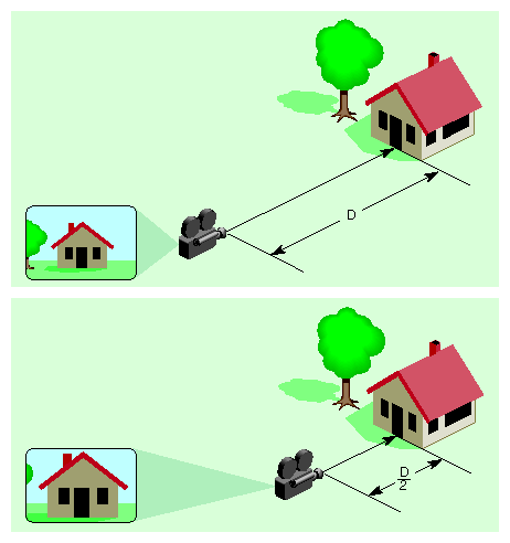
Dollying allows users to move a model of an object or a scene closer or farther away. Users move the object as if they were holding it in their hand. The user controls dollying by dragging while simultaneously pressing the left and middle mouse buttons during inspection. Dragging down in the viewing window moves the object closer; dragging up moves it farther away.
Figure 13-3 illustrates dollying from the implementation perspective. The look-at point and viewing direction are fixed. The camera (eyepoint) moves toward the look-at point along the viewing direction to move the object closer to the user. If the user wants to move the object further away, the camera would move away from the look-at point.
| Note: When users move closer to an object, they eventually reach the point where they would touch the object. As they dolly even farther forward, the eyepoint moves past the (fixed) look-at point as if the user just moved through the object. When the user passes this point, the tumble controls are “reversed” because the user is now dragging along the inside of the virtual trackball (see “Tumbling”) and along its backside. |
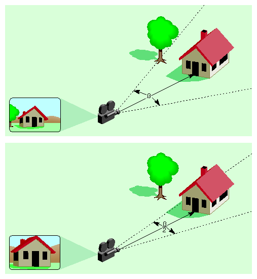
Dollying is different from zooming. In both cases the objects change in size in the viewing window. However, in contrast to dollying, zooming doesn't move the object closer or farther away from the user. Zooming instead allows users to change the viewing angle of the camera, the same way they would use a zoom lens on an actual camera. That is, as the user zooms out the viewing angle is increased so that the viewing area becomes larger and more of the scene is visible. This new larger viewing area is then mapped to the viewing window.
As shown in Figure 13-4, objects appear larger (or smaller) after zooming in (or out) even though the location of the camera hasn't changed. This is because the viewing angle changes but the size of the viewing window hasn't changed.
Panning allows users to move a model of an object or a scene up, down, left, or right in the viewing window. Users move the object as if they were holding it in their hand. The user controls panning by dragging while pressing the middle mouse button. The object moves in the direction of the drag; for example, dragging up in the viewing window moves the object up and dragging left moves the object left.
Figure 13-5 illustrates panning from the implementation perspective. The camera (eyepoint) moves in the plane perpendicular to the viewing direction. The camera moves opposite to the movement of the object. As shown in the figure, the camera moves right, which moves the scene to the left in the viewing window. The look-at point moves with the camera. The viewing direction is unchanged.
Seeking allows users to move an object in the scene into the center of the viewing window. In inspection, the user model is that the user is incrementally moving the object closer (see “Inspection Overview”). In navigation, the user model is that the user is incrementally moving closer to the object (see “Navigation Overview”).
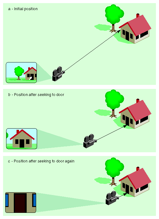
For both inspection and navigation, the user controls seeking by clicking on the object (or part of the object) of interest. Clicking on the object centers the object (or part) in the viewing window and brings the object and user closer together. Each additional click on the same object (or part) brings the object and user still closer. Figure 13-6 shows a simple example of seeking to the door of a house. The first click on the door positions the door in the center of the viewing window and halves the distance between the door and the user. The second click halves the distance again.
Many applications need to reserve clicking with the left mouse button for a more critical or useful function (for example, activating a link or initiating object behavior). In those applications, allow users to first activate a seek tool, then click with the left mouse button in the scene to actually seek.
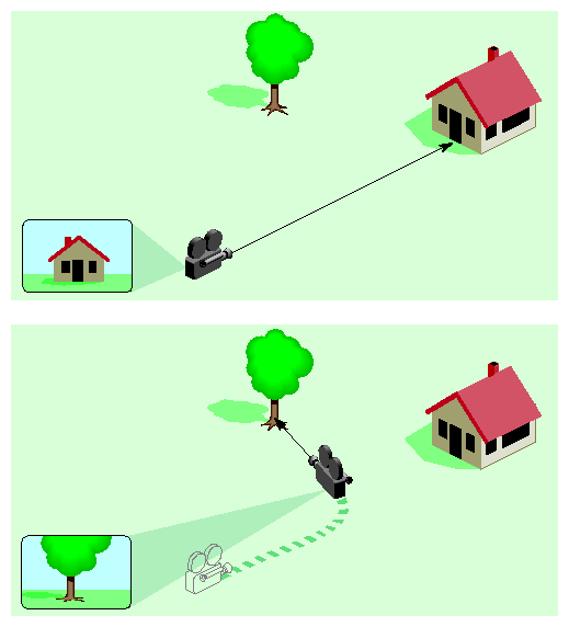
From the implementation perspective, seeking sets a new look-at point at the location of the user's click and moves the camera so that this new look-at point is at the center of the viewing window. The camera is also moved forward half the original distance between the camera and the object. Note that in the case of inspection, resetting the look-at point by seeking means that the camera tumbles around this new point after the seeking action.
This section first gives an overview of navigation, then describes three viewing functions that apply only to navigation (and not to inspection):
“Seeking,” which has the same effect in both inspection and navigation, is discussed in the preceding section.
Each function is first presented from the user's point of view, then discussed in terms of the implementation model.
Navigation is useful when users want to move through a world, for example, walk through a 3D model of a museum or an architectural model. In navigation, the user maneuvers through a fixed, immovable world by walking, flying, or another navigation mechanism.
The expected user model for navigation is that users are manipulating the camera. From the users' perspective, all navigation controls appear to manipulate the camera while the scene remains stationary. For example:
Pressing the left mouse button and dragging the pointer up while roaming moves the user farther forward into the scene. To achieve this, the application also moves the camera farther into the scene (see Figure 13-7).
Pressing the middle mouse button and dragging the pointer to the left while sidling sidesteps the user towards the left of the viewing window. To achieve this, the application also moves the camera to the left (see Figure 13-9).
Note that in both examples, users move the control (and pointer) in the direction they want the camera to move.
Table 13-3 provides an overview of the different functions available in navigation.
Table 13-3. Overview of Navigation Viewing Functions
Function | User Model | Implementation Model |
|---|---|---|
Roaming | User moves forward or backward in the scene. Turning changes direction of movement. | Camera (eyepoint) moves forward or backward along viewing direction in the same direction as the user action. Viewing direction moves in the direction that the user turns. Look-at point changes as the viewing direction changes. |
Tilting | User looks up or down. | Viewing direction moves in the direction that the user looks (up or down). Position of camera (eyepoint) remains fixed. Look-at point changes as the viewing direction changes. |
Sidling | User sidesteps left or right in the scene or “elevators” up or down in the scene. | Camera (eyepoint) moves in plane perpendicular to viewing direction. Camera moves in the same direction as user action. Viewing direction remains unchanged. Look-at point moves with camera. |
Seeking | User selects object (or part of object). Selected object is centered in viewing window and moved closer to user with each click. | Look-at point moves to where user clicked in the scene. Camera (eyepoint) turns so that look-at point is centered in viewing window. Camera moves closer by half the original distance between camera and object. |
Roaming (and turning) is the default viewing function for navigation. Users move through a fixed scene as if walking through it. While users are moving they expect to be able to turn to change the direction of the movement. Users control roaming by dragging with the left mouse button while the application is in view mode. Since users may sometimes want to turn without moving, dragging on the horizontal is interpreted differently than dragging in other directions as follows:
Dragging up in the viewing window moves the user forward into the scene; dragging down moves the user backwards out of the scene.
Dragging directly left on the horizontal in the viewing window turns the user left without any forward or backward movement; dragging directly right turns the user right without any movement.
Dragging in any direction above the horizontal both turns the user in that direction and moves the user forward in that direction; dragging in any direction below the horizontal both turns the user and moves the user backward in that direction.
From the implementation perspective, the camera (eyepoint) moves forward or backward along the viewing direction in the same direction as the user's action; that is, as the user moves forward, the camera moves forward (see Figure 13-7). The viewing direction moves in the same direction that the user turns; that is, as the user turns left, the viewing direction rotates left. If the user indicates a wish to turn but not move (by dragging the pointer directly left or right on the horizontal), the viewing direction changes appropriately but the camera doesn't move forward or backward. The look-at point changes as the viewing direction changes.
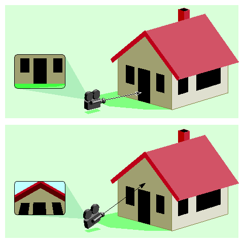
Tilting allows users to look up and down to see an object higher or lower than their current viewing direction in the scene. Tilting doesn't move the user. To move toward an object in the new view, the user has to use roaming (see “Roaming”). To control tilting, the user simultaneously presses the left and middle mouse buttons and drags. Dragging up in the viewing window tilts the user's head up to look up in the scene; dragging down allows the user to look down.
From the implementation perspective, tilting changes the viewing direction in the same direction the user's head is tilted (see Figure 13-8). As the user looks up, the viewing direction moves up; looking down moves the viewing direction down. The location of the camera (eyepoint) doesn't change. The location of the look-at point changes as the viewing direction changes.
Sidling allows users to sidestep left and right in the scene or to “elevator” up and down in the scene. Sidling moves the user left, right, up and down in the plane perpendicular to the viewing direction; it doesn't move the user forward or back in the scene. The user controls sidling by dragging while pressing the middle mouse button. The user moves in the direction of the drag; for example, the user drags left in the viewing window to sidestep to the left. Dragging up moves the user up as if riding on an elevator.
Figure 13-9 illustrates sidling from the implementation perspective. The camera (eyepoint) moves in the plane perpendicular to the viewing direction. The camera moves in the same direction that the user wants to move. As the user sidesteps left, the camera moves left. If the user moves up, the camera also moves up. The orientation of the camera remains unchanged. The look-at point moves with the camera.
When designing the user interface for a 3D application...
Provide a viewing interface regardless of other capabilities of the application (for example, editing).
When designing the user interface for 3D viewing...
Decide whether your application will support inspection, navigation, or both, then provide the appropriate viewing functions. If your application supports both inspection and navigation, choose one as the primary mode for viewing.
Use standard pointer shapes to indicate the current 3D viewing function.
When designing the user interface for INSPECTION in a 3D application...
Support the user model that users are manipulating a scene as though it were a single object they are holding in their hand (not the user model that users are manipulating a camera). From the user's perspective, all controls appear to manipulate the object or scene while the camera remains stationary.
Support tumbling as the default inspection function to allow users to view all sides of the scene.
Assign tumbling to dragging with the left mouse button.
Display the tumble pointer while the user accesses the tumble function.
Support dollying to allow users to move the scene closer or farther away.
Assign dollying to dragging with the left and middle mouse buttons pressed simultaneously.
Display the dolly pointer while the user accesses the dolly function.
Support panning to allow users to move the scene left, right, up, or down.
Assign panning to dragging with the middle mouse button.
Display the pan pointer while the user accesses the panning function.
Support seeking to allow users to change the look-at point and center the object of interest and to bring the object incrementally closer.
Support seeking as follows:
If your application needs to reserve clicking with the left mouse button for a more critical or useful function, allow users to seek by first activating a seek tool, then clicking with the left mouse button in the scene. Otherwise, support seeking without the use of a tool.
In either case, the user seeks by clicking on a part of the scene with the left mouse button. The application centers that part of the scene in the viewing window and moves the scene closer by half the distance between the camera and the object.
With each subsequent click on the same part of the scene, the scene again moves closer.
Display the seek pointer while the user accesses the seek function.
When designing the user interface for NAVIGATION in a 3D application...
Support the user model that the scene is stationary and the user is moving through this fixed, immovable world. From the user's perspective, all navigation controls appear to manipulate the camera (user's view into the world) while the scene remains stationary.
Support roaming as the default navigation function. In roaming, the user can move forward and backward, turn left and right, and turn while moving.
Assign roaming to dragging with the left mouse button.
Display the roam pointer while the user accesses the roaming function.
Support tilting to allow users to change their view of the scene by tilting their head up and down. Tilting doesn't move the user forward or backward.
Assign tilting to dragging with the left and middle mouse buttons pressed simultaneously.
Display the tilt pointer while the user accesses the tilting function.
Support sidling to allows users to sidestep left and right and to move up and down as if on an elevator.
Assign sidling to dragging with the middle mouse button.
Display the sidle pointer while the user accesses the sidling function,
Support seeking to allow users to move closer to an object in the scene.
Support seeking as follows:
If your application needs to reserve clicking with the left mouse button for a more critical or useful function, allow users to seek by first activating a seek tool, then clicking with the left mouse button in the scene. Otherwise, support seeking without the use of a tool.
In either case, the user seeks by clicking on a part of the scene with the left mouse button. The application centers that part of the scene in the viewing window and moves the scene closer by half the distance between the camera and the object.
With each subsequent click on the same part of the scene, the scene again moves closer.
Display the seek pointer while the user accesses the seek function.
When designing a user interface for viewing in a 3D application, developers often need to address the design issues discussed in this section:
Only a limited number of mouse and keyboard key combinations is available for interacting with an application. Users therefore can't easily have access to all necessary editing and viewing functions at the same time. Instead, they need to switch contexts between editing and viewing so that they can use the same mouse and keyboard combinations in the different contexts to access different functions.
This context switch is best done by splitting editing and viewing functionality into two separate explicit modes. Using explicit modes avoids a potentially confusing interface that may result if the user doesn't know whether the next action will change the view of the object or the object itself.
In general, when users work with an application that allows editing, they like to be offered several ways to access the viewing functions, and they like to always have quick access to these functions.
The following sections discuss several techniques for providing both viewing and editing capabilities to the user:
No matter how an application allows users access to viewing and editing, it's important to always display the correct pointer shape to let users know which function they are currently performing. See “Pointer Shapes for 3D Functions” in Chapter 12.
If an application supports editing, separate and explicit view and edit modes are highly recommended. This allows more flexibility in assigning functions to mouse and keyboard key combinations. In edit mode, mouse and keyboard input perform editing functions on selected objects and on the scene; in view mode, mouse and keyboard input perform viewing functions.
Users expect an obvious mechanism to switch modes, for example an item in a pull-down menu or a button on a tool palette that provides a variety of possible modes. In addition, users also expect to be able to switch modes using the <Esc> key (see “Using Modifier Keys in 3D Applications” in Chapter 12). Pressing this key takes the user to the next mode.
When they are editing, users expect to always have quick access to viewing with a view overlay. A view overlay is a temporary view mode that's available while the user holds down the <Alt> key (see “Using Modifier Keys in 3D Applications” in Chapter 12). As long as the <Alt> key remains pressed, mouse and keyboard input is temporarily interpreted as providing viewing input rather than editing input. Releasing the <Alt> key returns the application to standard editing operations. If the application is already in view mode when the user presses the <Alt> key, the <Alt> key is ignored.
A view overlay offers users quick access to temporary viewing but allows them to stay focused on the editing tasks at hand. This avoids forcing the user to make a heavyweight switch between edit and view modes. Although the view overlay is temporary, users still need to see the correct pointer shape feedback while accessing the viewing functions (for example, the roam pointer or tilt pointer). See “Pointer Shapes for 3D Functions” in Chapter 12.
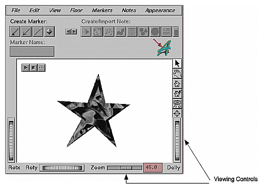
Applications can optionally provide separate user interface controls to access viewing functions. In this approach, all mouse input is interpreted as editing input unless the user is using the mouse pointer to manipulate a viewing control.
Figure 13-10 shows an application window with viewing controls around the sides and the bottom of the window. Manipulating the thumbwheels or sliders with the mouse affects viewing: For example, dragging the thumbwheel in the lower right hand corner of the window dollies the camera, which changes the view but doesn't edit it. Using the mouse in the viewing area of the window performs editing actions: for example, clicking on the star selects that object for editing.
Another optional method of addressing the conflict between viewing and editing input is to assign all viewing actions to one dedicated input device, such as a spaceball. All input from the dedicated input device performs viewing functions; input from other devices performs editing functions. This approach provides more input bandwidth: Context switching between viewing and editing is handled by the choice of input device.
When designing a viewing interface, you must decide whether to offer users only one view of the scene (single-viewport) or multiple views simultaneously (multi-viewport). Multiple views may be, for example, one close-up and one distance view or one view from the top and one from each side. This section presents “Single-Viewport Viewing” and “Multi-Viewport Viewing,” discussing their advantages and disadvantages.
In the single-viewport model, only one view of the scene can be projected to the single viewport at any given time, even if there are multiple cameras in the scene. This is a serially multiplexed approach; different views are presented one after another in the same viewport and the user can switch among them.
By default, the viewport provides a perspective view of the scene. The view updates as the user selects different cameras.
Single-viewport viewing has these advantages:
Performance—Updating the contents of one view is less computationally expensive than updating two or more views. Application performance deteriorates as the number of views increases, so single-viewport viewing is faster than multi-viewport viewing.
Space—The view doesn't need to share space with other views in the application window. The total viewing area is dedicated to a single view; this allows the largest possible representation of the 3D data.
Simpler user model—Users have to deal only with one view and one window. In contrast, a multi-viewport model requires that users determine the relationship among the different views or decide how changes in one view influence the other views.
In the multi-viewport model, two or more views of a scene are simultaneously available. Typically, there are four views: front, top, one side (typically the right), and perspective.
A view isn't necessarily bound to a particular camera. For each view, the user can choose which camera to use and what each camera views. For example, to view an object from the bottom that's currently visible from the front, the user can either find a camera that displays it from the bottom or tumble or roam to get that view.
Multi-viewport viewing has the advantage that it allows simultaneous views of different representations of data. Users can examine and edit data from different perspectives simultaneously and can edit and examine data across multiple views without having to switch views. This is important for editing complex objects or during scene composition. While performance can be worse with multiple views (because more windows must be updated during viewing operations), experienced users find multiple views useful because they can coordinate operations across multiple viewports to get more accurate feedback on the actions they are performing.
Viewing is critical to interacting with 3D environments and applications. The more responsive the application is during viewing, the more realistic and compelling the user's experience.
To achieve realistic user interaction, an application has to maintain at least 8 fps while the user interacts with the view. The frame rate—number of frames per second (fps)—is a good gauge of acceptable viewing performance:
If the frame rate drops below 8 fps, users typically find interacting with the application cumbersome.
In an editing context, 10-12 fps can be sufficient.
15 fps is the minimum frame rate to give the user a fluid, in-control experience. Action games or immersive experiences may require a greater frame rate to achieve that goal.
Some 3D scenes are so complex that just rotating the view becomes computationally expensive. In that case, the 3D scene can't be rendered at an acceptable frame rate. In such situations, applications must provide automatic adaptive rendering, user-controlled adaptive rendering, or both:
In automatic adaptive rendering, the application always maintains viewing responsiveness at the expense of scene fidelity.
In user-controlled adaptive rendering, users explicitly choose between adaptive rendering (that is, maintaining viewing responsiveness at the expense of scene fidelity) and fully rendering the contents of the scene (but taking a performance hit during viewing). This choice is important if users sometimes need fully rendered, high-fidelity scenes and, therefore, need to turn off adaptive rendering.
| Note: It isn't acceptable to let the frame rate drop below 8 fps without explicit user confirmation. |
Adaptive rendering maintains viewing performance by changing the rendering characteristics of objects and elements during viewing operations. Typically, some detail is omitted from the display to reduce the computational requirements. As a result, a higher frame rate is achieved at a somewhat lower level of fidelity. Once viewing stops, the scene is returned to its original fidelity. Most users are satisfied with such a trade-off. Without adaptive rendering, users complain of poor performance or sluggishness. Adaptive rendering maintains responsive behavior without reducing functionality or impeding user tasks.
To implement adaptive rendering, an application can use techniques such as turning off texturing when an object is being moved, or using wireframe models. If an application has multiple views, adaptive rendering can be implemented by updating only one of the views. Then, when the view is no longer changing, the other views can be updated.
Note that if an application uses only automatic adaptive rendering, it needs to provide users easy access to fully rendered scenes. At a minimum, this should occur when the user stops interacting with the view.
To make viewing quickly and easily accessible in 3D applications...
Always provide ready access to viewing no matter what the user is doing (for example editing).
When designing a viewing interface for a 3D application that also supports editing...
Display the appropriate pointer depending on the task the user is performing:
While the user is accessing editing functions, display the edit pointer.
While the user is accessing viewing functions, display the appropriate view pointer based on the user's current viewing function (for example, the roaming pointer if the user is currently navigating a scene).
Provide a modal interface to viewing and editing whenever possible.
Provide an obvious mechanism for changing between the view and edit modes, such as buttons in a tool palette or entries in a pull-down menu.
Reserve the <Esc> key for switching between the view and edit modes.
Always provide a view overlay for quick access to viewing. That is, when the primary task is editing, the user can at any time temporarily enter a view mode by pressing and holding the <Alt> key. The user can release the <Alt> key to return the application to edit mode.
Reserve the <Alt> key for providing access to a view overlay. If the user is already in view mode, the <Alt> key has no effect.
Display the appropriate pointer for the current viewing function (for example, the tumble pointer or the roaming pointer) while the user is accessing a view overlay.
Optionally provide additional ways to access viewing, for example, offer viewing fixtures or split viewing and editing input across separate dedicated input devices.
When deciding between a single viewport and multiple viewports...
Use a single viewport if the user doesn't need to do much editing, performance or screen real estate is critical, you need a simple user model, or if several of these conditions are met.
Support multiple viewports if the user needs two or more views of the data simultaneously (such as when editing complex objects or working on scene composition) and performance isn't a critical issue.
When designing a viewing interface for a single viewport...
Use the perspective view of the scene as the default view.
Update the single-viewport view with a new view as the user selects different cameras.
When making viewing performance design decisions...
Support a minimum frame rate of 8 fps when the user is interacting with the view.
Ideally, support a minimum rate of 10-12 fps for editing and a minimum frame rate of 15 fps for a realistic interactive experience.
If the frame rate drops below 8 fps, provide at least one of the following solutions:
Automatic adaptive rendering, where the application always maintains an acceptable frame rate at the expense of scene fidelity.
User-controlled adaptive rendering, where the user explicitly chooses between adaptive rendering (acceptable frame rate but loss of detail) and fully rendering the contents of the scene (at a possibly unacceptably low frame rate).
If users sometimes need fully rendered, high-fidelity scenes and the frame rate is likely to drop below 8 fps, provide user-controlled adaptive rendering.
If you application only provides automatic adaptive rendering, provide users ready access to fully rendered scenes. At a minimum, this should happen when the user stops interacting with the view.
