Sirius Video is a video option for IRIS workstations equipped with RealityEngine, RealityEngine2, or VTX graphics. It fully integrates broadcast-quality video with Silicon Graphics supercomputer graphics capabilities. Sirius Video can also be installed in CHALLENGE servers and POWER Series server configurations, making its broadcast-quality video a network resource.
The option utilizes one VME slot; input and output connectors are on a breakout box that can be mounted in a rack. Multiple Sirius Video boards can be operated in serial or parallel for multilayered video effects or video server capability.
Sirius Video supports real-time input and output of video in the full range of broadcast video formats. You can view graphics images from the workstation in low resolution, or capture video images in real time and view them on the workstation monitor. Sirius Video enables you to apply the full power of RealityEngine graphics to manipulate live video images.
Sirius Video enables you to blend graphics and frames from video in many ways, including alpha blending and chroma and luma keying. You can also generate pixel fades and wipes in real time from external alpha. You can blend video input with workstation-derived images for video output.
For controlling videotape recorders, Sirius Video includes an on-board V-LAN controller (transmitter) to send high-level VTR commands over a coaxial network to V-LAN receivers purchased from third parties.
Sirius Video is designed for the sophisticated video user in a professional or research environment. It fully utilizes all calls and controls in the Silicon Graphics Digital Media library, such as the Video Library, as well as controls that are native to Sirius Video only.
This chapter explains
major components of Sirius Video
video formats and video handling
the V-LAN interface
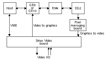
Figure 1-1 diagrams how the Sirius Video expansion board (VO2) interacts with other workstation components.
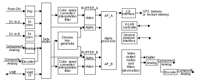
Figure 1-2 diagrams Sirius Video board functionality.
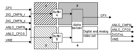
The Sirius Video expansion board can be divided into four quadrants, as shown in Figure 1-3. Frame buffers serve as the quadrant boundaries. The frame rates and clock rates of each quadrant are fully independent, allowing the quadrants to have different inputs and outputs in different timings.
The rest of this section details the functionality of these system components:
inputs and outputs
digital video ports
VME interface
data router
color-space converters
frame buffers
alpha processor and chroma key generator
interpolation and decimation filters
video-to-graphics (CP) interface
Sirius Video supports real-time input and output of video at field rates of 50 or 59.94 frames per second in the full range of video and Silicon Graphics graphics formats. The Sirius Video breakout box provides input to and output from the on-board field buffers, as summarized in Table 1-1.
Table 1-1. Sirius Video Inputs and Outputs
Input to Sirius Video Frame Buffers | Sirius Video Destination Frame Buffers |
|---|---|
10-bit digital (4:4:4:4, 4:2:2:4, or 4:2:2) | |
10-bit analog RGBa/YUVa | 10-bit digital RGBa to GFX |
10-bit digital RGBa from the | VME 8-bit or 10-bit/component |
8-bit composite (NTSC, PAL, or S-VHS) |
|
VME 8-bit or 10-bit/component |
|
Video can be directed to more than one output at a time, making possible a broad range of processing and monitoring arrangements.
The Sirius Video breakout box has two 10-bit digital video ports for equipment that complies with the CCIR 601 standard. Each port supports a parallel interface at 27 MHz and an optional serial interface (marketing code D4-SD1) at 270 MHz.
The ports can be configured for 4:4:4:4 or 4:2:2:4 dual-link mode; for 4:2:2 single-link mode, alpha is ignored.
Each port consists of two unidirectional interconnections, Link A and Link B:
The video format selected determines Link A and Link B usage. For more information on the Link A and B connectors on the breakout box, see Table A-9 in Appendix A, “Technical Specifications.”
For more information, see the following standards, which contain provisions for video signals:
CCIR 601-2: Encoding Parameters of Digital Television for Studios (4:2:2 component video signals, single link)
ANSI/SMPTE 125M-1992: Television—Component Video Signal 4:2:2—Bit-Parallel Digital Interface
SMPTE Recommended Practice (RP) 175-1993: Digital Interface for 4:4:4:4 Component Video Signals (Dual Link)
SMPTE 259M, Television—10-Bit 4:2:2 Component and 4fsc NTSC composite Digital Signals—Serial Digital Interface
SMPTE RP 157-1990: Key Signals
The VME interface on the Sirius Video board initializes and configures the hardware and, in master mode, transfers video to and from system memory. A Sirius Video application can send live video to raster or texture memory in the graphics subsystem, or it can send the video to host memory over the VME bus. Regardless of input format, the video stream within Sirius Video is 4:4:4:4 RGBa/YUVa, 10 bits per component. See Appendix A, “Technical Specifications,” for more details on this interface.
The format of the data sent over the VME bus is user-controlled; Table 2-4 in Chapter 2, “Programming Sirius Video,” has details on packing formats.
The data router subsystem performs crosspoint switching. The data router subsystem is comprised of four routers, one for each component (YUVa or RGBa). Any input source and its alpha can be sent to either frame buffer.
In data router mode, five input channels are multiplexed onto two separate output channels. Three of the five inputs can also go through a lookup table.
Three color spaces are native to Sirius Video: RGBa, CCIR601, and full-range YUV (not compressed into the CCIR range). Any color space can be converted to any other color space on input or output. Specifying a format includes a color space; for example, to capture D1 data as RGB, use component digital format at the appropriate video source node and RGB at the memory drain node.
Color-space conversion is accomplished in hardware. Each of the two inputs to the frame buffers has a digital color space converter for YUV/RGB color-space conversion, which is a 3 x 3 matrix multiplier with programmable coefficients. The matrix processes 12 data bits and uses 10-bit coefficients and 23-bit precision internally. Lookup tables control overflow and underflow, rounding two's complement numbers.
Sirius Video can also maintain the color space of the input source throughout the video stream, rendering the digital processing of the video signal transparent.
| Note: For more information on color-space conversion, see Appendix D, “Sirius Video Color-Space Conversions,” later in this guide. |
The two Sirius Video frame buffers are symmetrical, except that the alpha buffer of frame store A can be accessed independently of its corresponding video buffer, whereas the same is not true of the alpha buffer of frame store B. Each frame buffer is ten bits wide.
Each frame buffer stores four fields of R/R-Y, G/Y, B/B-Y, and alpha pixels. The four component field buffer memory is comprised of field memory chips, where each chip is organized as a 256 K deep FIFO with two data ports. Each port has its own dedicated control and clock signals. Each buffer has its own controller, which contains the logic that generates the signals controlling reads and writes to the buffers.
The four field buffers are configured as a ring and are accessed sequentially. A field buffer cannot be written to and read from in the same operation; a buffer's contents cannot be displayed while it is being written to. If the write and read rates differ substantially, then paired fields, or frames, are dropped or repeated as needed.
The alpha processor produces alpha blends from the inputs to the two alpha buffers (A and B). The alpha processor blends the video and rate/scan-converted graphics based on the values of the alpha specified for each channel. The alpha can be from an external source or sources or graphics alpha, or can be generated from the chroma key generator. Color or alphas can also be passed through to output without going through the blend function.
The chroma key generator extracts an alpha from any input channel; it can direct its output to the alpha frame buffers.
Digital filters aid in the conversion of video between 4:2:2 and 4:4:4 formats. The filters are 55-tap, fixed-coefficient, linear-phase half-band (low-pass) filters that can halve or double the sample rate.
When a 4:2:2 input signal is selected, interpolating filters on each chroma difference channel can be used to double the sampling rate of U and V. A line FIFO on the Y channel acts as a programmable delay element to compensate for the delays produced by the filtering. If the filters are bypassed, U and V are replicated, not interpolated.
When 4:2:2 output mode is selected, decimating filters can be used to halve the sampling rate of U and V. The same types of filters are used to provide two times over-sampled digital data to the digital-to-analog converters for component output.
The CP interface moves data between Sirius Video and the Geometry Engine® (GE) board in the graphics subsystem. The CP interface consists of a controller, a matrix multiplier, dedicated lookup tables, a frame buffer, and data drivers. Bandwidth is 40 MHz.
The Sirius Video CP interface can convert data from YUVa to RGBa and format the data for the raster or texture memory. The formatted video data can then be sent over the 48-bit 33 MHz CP bus to graphics, packed as follows:
RGBa_12 raster data
RGBa_5 texture data (R = 5 bits, G = 6 bits, B = 5 bits)
RGBa_4 texture data (R = 4 bits, G = 4 bits, B = 4 bits)
RGBa_8 texture data (R = 8 bits, G = 8 bits, B = 8 bits)
Table 1-2 video input and output formats that Sirius Video supports.
Table 1-2. Sirius Video Video Formats
Port | Formats Supported |
|---|---|
Input |
|
Output |
|
Sirius Video displays full-size video windows in NTSC (646 x 486 or 720 x 486) and PAL (768 x 576 or 720 x 576) formats.
This section explains aspects of Sirius Video workstation graphics and video manipulation:
scan conversion/pixel averaging
video-to-graphics conversion
live video
blending and keying
On graphics systems, graphics and its alpha can be captured and converted to several sizes of 525 and 625 video. Output is always to a standard video size; the grab area can be changed. The captured graphics can also be passed through the system without scan conversion.
In pixel averaging, Sirius Video performs a resolution reduction of one image into another using filtering and decimation. A 1280 x 972-line portion of a workstation image can be converted to a 525-timing image (646 x 486) in real time by a vertical decimation of two and a combination of horizontal decimation and zooming. If 1280x1024 is converted to 646x486, the result is filtered down to 646x512, and then further decimated to 646x486.Likewise, a workstation image can be converted to a 625-timing image (768 x 576) in real time by a three-fifths decimation horizontally and vertically.
Using filtering, Sirius Video can convert an arbitrarily sized region of the workstation display to a video-sized raster. Some loss of sharpness in image quality might occur.
On Sirius Video installed in servers, scan conversion is not available.
If Sirius Video and Multi-Channel Option are installed on the same graphics pipeline of your system, Sirius Video is not capable of live graphics to video, either directly or pixel-averaged. (You can, however, snap the workstation display, save it as a file, and send the file to video.) Live video input is possible if hinv returns this report:
Sirius Video: unit 0 revision 4 on bus 0 with CPI BOB options |
Live video output and input are possible if hinv returns this report:
Sirius Video: unit 0 revision 4 on bus 0 with DGI CPI BOB options |
Sirius Video processes video pixels by software calls to the Silicon Graphics Graphics Library™ and other compatible libraries allowing, for example, the use of video for texturing.
A Sirius Video application uses calls to the IRIS Video Library (VL), the IRIS Graphics Library™, or other compatible libraries of custom routines to generate graphics effects with the video, including windows, zooms, and pans.
The interface to the graphics subsystem operates in field or frame mode. An application can select the number of bits (48, 32, or 16) formatted per pixel.
Data can be sent to memory in two modes:
Sirius Video supports alpha blending of any two inputs in real time. Blending can be based on graphics-buffer alpha planes, external alpha values, or output of the on-board alpha/key generator.
Path A alpha values can come from
graphics buffer alpha planes
VME
any input alpha source
Path B alpha values can come from
alpha channel of the source driving path B
alpha/key generator output derived from the source driving path B
An external 10-bit alpha key can be used for blending; the alpha processor generates an output or destination alpha from any pair of frame buffer alpha inputs.
Sirius Video fully supports chroma and luma keys. Source input is processed in the 3 x 3 matrix multiplier; editable lookup tables can then be used to manipulate the keys.
Component outputs from lookup tables are used to produce an alpha/key in the alpha/key generator. Edges on chroma or alpha keys can be softened.
| Note: Chapter 3, “Sirius Video Blending and Keying,” is a complete guide to using Sirius Video blending and keying capabilities. |
V-LAN is a video device network protocol designed and implemented by Videomedia® Inc., to provide reliable, frame-accurate control of professional and industrial-quality video equipment. The Sirius Video on-board V-LAN controller (transmitter) handles high-level VTR commands and distributes them over a coaxial network.
To use the V-LAN interface, purchase a receiver from Videomedia that is appropriate for the VTR equipment you have, and attach it to the V-LAN network connector on the Sirius Video breakout box. You can attach as many as 31 V-LAN receivers, each controlling a particular class of VTR.
The Sirius Video on-board V-LAN controller reduces the cost of tape control. Since you do not need to purchase a V-LAN controller unit, the single coaxial connection also has the advantage of replacing the tangle of RS-422 cables typically found in postproduction environments.
The Sirius Video software implements V-LAN commands as controls. Chapter 5, “Controlling the V-LAN Interface,” later in this guide contains complete information for using V-LAN with Sirius Video.
| Note: Other tape control devices can work with Sirius Video by interfacing triggered events via the GPI connectors on the Sirius Video breakout box. |


