This appendix illustrates how to connect your video equipment to connectors on the Sirius Video breakout box and how to use the video control panel vcp to set the Sirius Video board to match your installation.
This appendix explains
setting up digital source video
setting up analog source video
setting up an external sync source
setting up the output (drain)
adjusting graphics source or drain timing
adjusting texture drain timing
saving settings
Sirius Video has two 10-bit digital video ports for equipment that complies with the CCIR 601 standard. Each port supports a serial interface; these ports are on the optional serial digital board for the breakout box.
The ports can be configured for 4:4:4:4 or 4:2:2:4 dual-link mode; for 4:2:2 single-link mode, ignore the alpha.
Each port consists of two unidirectional interconnections, Link A and Link B:
To set up for a digital video source, follow these steps:
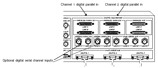
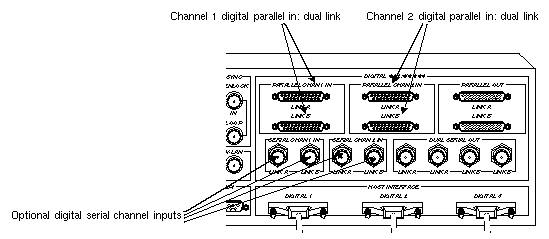
Connect the digital source equipment into the appropriate socket on the breakout box.
Figure C-1 points out sockets for single-link mode.
Figure C-2 points out sockets for dual-link mode.
-
/usr/sbin/vcp
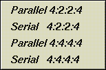
In the Digital Video Source section of the control panel vcp for the channel(s) you are using, select the format that matches your equipment, as shown in Figure C-3.
In the Digital Video Source portion of the panel for the channel(s) you are using, select the timing that matches your equipment: CCIR 525 or CCIR 625.
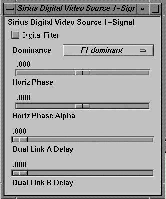
To adjust horizontal phase for each digital video channel and its separate alpha line, if used, select “Digital Video Source 1” or “Digital Video Source 2” in the Pro menu, and then select “Signal Controls,.” The Sirius Digital Video Source [1, 2] window appears, as shown in Figure C-4.
The windows for Digital Video Source 1 and Digital Video Source 2 are identical.
To enable conversion of 4:2:2:4 to 4:4:4:4 input, check the Digital Filter check box.
If you are using a dual link for 4:4:4:4, use the Dual Link Delay slider to adjust the delay of one link relative to the other to compensate for delay differences between the links.
To set up for an analog source, such as Betacam, M-II, S-Video, or NTSC/PAL, follow these steps:
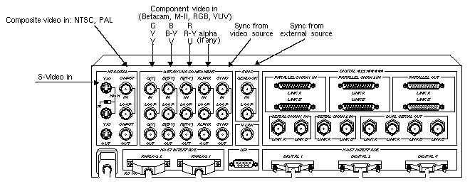
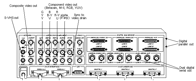
Connect the analog source equipment into the appropriate socket on the input row of the analog side of the breakout box, as shown in Figure C-5.
If necessary, call up the panel (/usr/sbin/vcp).
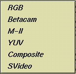
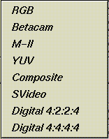
In the Analog Video Source portion of the control panel vcp, select the format that matches your equipment, as shown in Figure C-6.
In the Analog Video Source portion of the panel, select the timing that matches your equipment: 525, 625, CCIR 525, or CCIR 625.

Note: In the case of large amounts of jitter, use CCIR 525 instead of 525, and CCIR 625 instead of 625. If you are syncing to the analog input, make sure the sync signal is cabled to the SYNC IN port on the breakout box, as shown in Figure C-5.
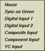
In the Analog Video Source portion of the panel, you can select the genlock sync source that matches your equipment, as shown in Figure C-7.

Note: To genlock to an external sync source, see “Setting Up an External Sync Source,” later in this appendix.
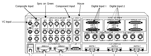
Table C-1 and Figure C-8 summarize the correspondence between these menu choices and breakout box connectors.
Table C-1. Genlock Sync Menu Choices and Breakout Box Sockets
Genlock Sync Menu Choice
Breakout Box Socket
House
SYNC
GENLOCKSync on Green
GBRA/YUVA COMPONENT
G(Y)Digital Input 1
PARALLEL CHAN 1 IN or SERIAL CHAN 1 IN
Digital Input 2
PARALLEL CHAN2 IN or SERIAL CHAN2 IN
Composite Input
NTSC/PAL
CMPSTComponent Input
GBRA/YUVA COMPONENT
SYNCYC Input
NTSC/PAL
Y/C

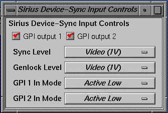
Note: If you experience problems genlocking to unstable video sources such as VCRs, VTRs, and laser disc players, try routing the video output from these devices into an external time base corrector, and feed the time base corrector's output into the corresponding connector on the Sirius Video breakout box. To set the voltage level for the genlock sync source, use the vcp Pro menu. In the Pro menu, select “Device Controls”, and then select “Synchronization Controls.” The Sirius Device-Sync Input Controls window appears, as shown in Figure C-9.
To set the voltage level, select Video (1 V peak-to-peak) or TTL (4 V peak-to-peak) in the Sync Level menu item.
Use the sliders to adjust the horizontal phase for the picture.
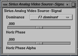
To set field dominance or adjust horizontal phase for the video and its separate alpha, if any, select “Analog Video Source” in the Pro menu, and then select “Signal Controls.” The Sirius Analog Video Source-
Signal window appears, as shown in Figure C-10.
To set field dominance, select at the “Dominance” menu item:
“F1 dominant”: the edit occurs on the nominal video field boundary
“F2 dominant”: the edit occurs on the intervening field boundary
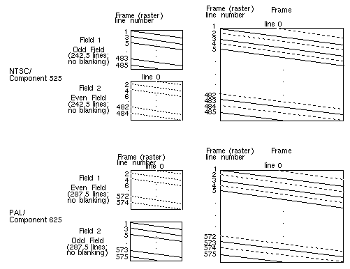
Figure C-11 shows fields as defined for NTSC and PAL.

Note: In digital formats and other input modes, half lines become full lines.
Users typically want to edit on Field 1 boundaries, where Field 1 is defined as the first field in the video standard's two-field output sequence. 525 standards send the second (whole) raster line out to begin the first field, and the first (half) raster line out to begin the second field; 625 standards send the first (half) raster line out to begin the first field, and the second (whole) raster line to begin the second field.
Some users may want to edit on F2 boundaries, which fall on the field in between the video standard's frame boundary. To do so, use this control, then program your deck to select F2 edits.
NTSC users might need to vary their field dominance choice, depending on the origin of the input material they are to edit.

Note: To output a set of frames, they must be deinterlaced into fields differently, depending on the choice of output field dominance. For example, when F1 dominance is selected, the field with the topmost line must be the first field to be transferred; when F2 dominance is selected, the field with the topmost line must be the second field to be transferred. Deinterlacing must be specified in the application; the Sirius Video example program sir_memtovid.c code contains an example of how to consult the field dominance control to determine deinterleave order. /* * Set the memory node's timing based upon the video drain's timing, * which has been set up by the daemon from the defaults file, or by * the user via vcp. * * When we get around to reading image files, we'll check the file * size against the size reported by the VL for this node: if the file * size does not match the format's, we'll punt. */ if (vlGetControl(svr, MEMtoVIDPath, drn, VL_TIMING, &drainTiming) < 0) { vlPerror(“GetControl(VL_TIMING) on video drain failed”); exit(1); } if (vlSetControl(svr, MEMtoVIDPath, src, VL_TIMING, &drainTiming) < 0) { vlPerror(“SetControl(VL_TIMING) on memory source failed”); exit(1); } /* * Read the video drains's field dominance control setting and timing, * then set a variable to indicate which field has the first line, so that * readimage() will know how to deinterleave frames to fields. */ if (vlGetControl(svr, MEMtoVIDPath, drn, VL_SIR_FIELD_DOMINANCE, &dominance) < 0) { vlPerror(“GetControl(VL_SIR_FIELD_DOMINANCE) on video drain failed”); exit(1); } is_525 = ((drainTiming.intVal == VL_TIMING_525_SQ_PIX) || (drainTiming.intVal == VL_TIMING_525_CCIR601)); switch (dominance.intVal) { case SIR_F1_IS_DOMINANT: if (is_525) { F1_is_first = 0; } else { F1_is_first = 1; } break; case SIR_F2_IS_DOMINANT: if (is_525) { F1_is_first = 1; } else { F1_is_first = 0; } break; } /* * Read the video drain's field dominance control setting and set a * variable to indicate which field has the first line, in case readimage() * needs to deinterleave frames to fields. */ if (vlGetControl(svr, MEMtoVIDPath, drn, VL_SIR_FIELD_DOMINANCE, &val) < 0) { vlPerror(“GetControl(VL_SIR_FIELD_DOMINANCE) on video drain failed”); exit(1); } switch (val.intVal) { case SIR_F1_IS_DOMINANT: F1_is_first = 1; break; case SIR_F2_IS_DOMINANT: F1_is_first = 0; break; }To assemble fields to frames, the application must consult the field dominance control in order to determine the interleave order. the Sirius Video example program sir_vidtomem.c contains an example of how to consult the field dominance control to determine interleave order.
    /*
     * Set the memory node's timing based upon the video source's timing,
     * which has been set up by the daemon from the defaults file, or by
     * the user via vcp.
     */
    if (vlGetControl(svr, path, src, VL_TIMING, &timing) < 0) {
	vlPerror(“GetControl Failed”);
	exit(1);
    }
    if (vlSetControl(svr, path, drn, VL_TIMING, &timing) < 0) {
	vlPerror(“SetControl Failed”);
	exit(1);
    }
    /*
     * Read the video source's field dominance control setting and timing,
     * then set a variable to indicate which field has the first line, so that
     * writeimage() will know how to interleave fields to frames.
     */
    if (vlGetControl(svr, path, src,
	VL_SIR_FIELD_DOMINANCE, &dominance) < 0) {
	vlPerror(“GetControl(VL_SIR_FIELD_DOMINANCE) on video source failed”);
	exit(1);
    }

    is_525 = ((timing.intVal == VL_TIMING_525_SQ_PIX)
	   || (timing.intVal == VL_TIMING_525_CCIR601));

    switch (dominance.intVal) {
	case SIR_F1_IS_DOMINANT:
	    if (is_525) {
		F1_is_first = 0;
	    } else {
		F1_is_first = 1;
	    }
	    break;
	case SIR_F2_IS_DOMINANT:
	    if (is_525) {
		F1_is_first = 1;
	    } else {
		F1_is_first = 0;
	    }
	    break;
    }
To adjust gain and offset for component input video, follow these steps:
Select “Live Video Input” in the Utilities menu. The Live Video window appears, displaying video from the analog source.
Make sure that “RGB”, “Betacam”, “M-II”, or “YUV” is selected at Format in the Analog Video Source portion of the panel.
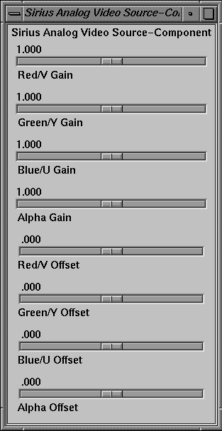
Select “Analog Video Source” in the Pro menu, and then select “Component.” The Sirius Analog Video Source Component window appears, as shown in Figure C-12.
Use the Gain sliders to adjust the voltage level to output the desired amount of red, green, blue, and alpha on each channel.
Use the Offset sliders to adjust the active region of the video relative to the black region.
| Note: Although the labels for gain and offset are shown as .000 to 2.000 in the window, actual low and high values vary per board. Actual values are displayed when the sliders are at the minimum and maximum positions. |
To adjust attributes for composite and Y/C input video, follow these steps:
Select “Live Video Input” in the Utilities menu. The Live Video window appears, displaying video from the analog source.
Make sure that “Composite” or “SVideo” is selected at Format in the Analog Video Source portion of the panel.
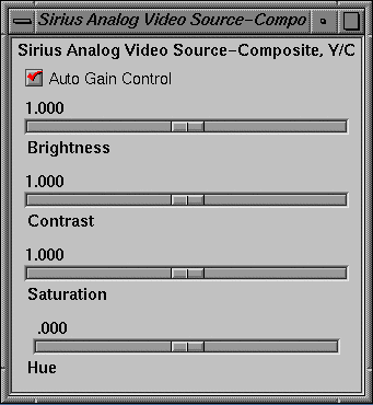
Select “Analog Video Source” in the Pro menu, and then select “Composite, Y/C.” The Sirius Analog Video Source Composite, Y/C window appears, as shown in Figure C-13.
Use the sliders to adjust the picture.
To set up Sirius Video for an external sync source, follow these steps:
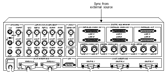
Connect the sync source equipment into the GENLOCK IN socket on the SYNC section of the breakout box, as shown in Figure C-14.
If you are using the same signal for other equipment, attach a BNC cable to the LOOP socket under GENLOCK IN socket to loop the signal through the breakout box. Make sure the final element in the chain is terminated.
If Sirius Video is the last element in the sync chain, make sure the terminator is attached to the LOOP socket under GENLOCK IN socket.
In the Genlock Sync menu of the Video Drain section of the control panel, select the format that matches your equipment, as shown in Figure C-15.
For correspondences between these menu choices and sockets on the breakout box, see Table C-1 and Figure C-8, earlier in this appendix.
To set the voltage level for the external sync source, select “Device Controls” in the vcp Pro menu, and then select “Synchronization Controls.” The Sirius Device-Sync Input Controls window appears, as shown in Figure C-16.
To set voltage level, set the voltage level to “Video” (1 V peak-to-peak) or “TTL” (4 V peak-to-peak) in the Genlock Level menu item.
| Note: The GPI 1 In Mode and GPI 2 In Mode menu items are discussed in Chapter 4, “Controlling the General-Purpose Interface (GPI).” |
To set up the drain, follow these steps:
Connect the drain equipment into the appropriate socket on the breakout box, as shown in Figure C-17.
In the Video Drain section of the control panel, select the format that matches your equipment, as shown in Figure C-18.
In the Video Drain portion of the panel, select the timing that matches your equipment: 525, 625, CCIR 525, or CCIR 625.

Tip: In many situations, CCIR timing gives better results. If your drain equipment is synced to the workstation, select “Standalone (internal)” in the Sync Select menu item.
To sync output to a source other than the workstation, select “Genlock” and select a choice in the Genlock Sync menu item, as shown in Figure C-19.
For correspondences between these menu choices and sockets on the breakout box, see Table C-1 and Figure C-8, earlier in this appendix.
You can set signal controls for the drain:
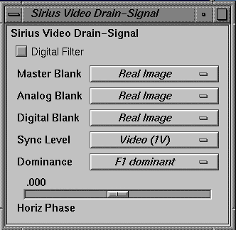
To do so, select “Drain” in the Pro menu, and then select “Signal Controls.” The Sirius Video Drain-Signal window appears, as shown in Figure C-20.
Use this window as follows:
To convert 4:4:4:4 to 4:2:2:4 output, check the Digital Filter check box.
To set analog output to black/blank when you are running digital output formats and vice versa, select “Black/Blank” at the Analog Blank menu item. To set both analog and digital output to black/blank simultaneously, select it at Master Blank.
To select sync voltage level, select “Video” (1 V peak-to-peak) or “TTL” (4 V peak-to-peak).
To set field dominance, at the “Dominance” menu item select “F1 dominant” for the edit to occur on the nominal video field boundary, or “F2 dominant” for the edit to occur on the intervening field boundary.
See Figure C-11 and “Setting Up Analog Source Video,” earlier in this appendix, for more information.
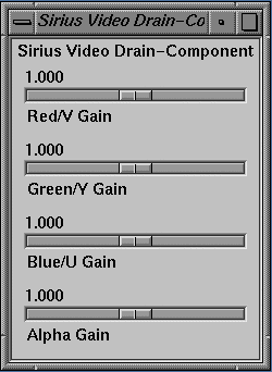
To adjust gain for component output video, select “Video Drain” in the Pro menu, and then select “Component.” The Sirius Video Drain Component window appears, as shown in Figure C-21.
Move the sliders to adjust the picture.

Note: Although the minimum and maximum values for gain are shown in the window as .000 to 2.000, actual ranges vary. These values are displayed when you move the sliders to the minimum and maximum (far left and far right) positions, respectively.
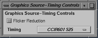
To set flicker reduction or timing (525, 625, CCIR 525, CCIR 625) for the graphics source, select “Graphics Source” in the vcp Pro menu, and then select “Coding Controls.” The Graphics Source-Timing Controls window appears, as shown in Figure C-22.
Click the check box to activate flicker reduction. Select the appropriate timing at the “Timing” menu item.
Likewise, to set timing (525, 625, CCIR 525, CCIR 625) for the graphics drain, select “Graphics Drain” in the vcp Pro menu, and then select “Coding Controls.” The Graphics Source-Timing Controls window appears, as shown in Figure C-23.
Select the appropriate timing at the “Timing” menu item.
To set timing (525, 625, CCIR 525, CCIR 625) for the texture drain, select “Texture Drain” in the vcp Pro menu, and then select “Coding Controls.” The Texture Drain-Timing Controls window appears, as shown in Figure C-24.
Select the appropriate timing at the “Timing” menu item.
Once you have set values in vcp to match your installation, save them; they are written to /usr/etc/video/videod.defaults. Select “Restore Settings” on the video control panel File menu to load the values in this file to vcp.
The last settings saved are automatically loaded every time the system is reinitialized. If the panel is running, current settings are in effect.
| Note: You do not need to open the panel to put its settings into effect. |
You can also use File menu choices to restore the factory defaults and close the panel.
