IRIX provides for two general methods of controlling devices, at the user level and at the kernel level. This chapter describes the architecture of these two software levels and points out the different abilities of each. This is important background material for understanding all types of device control. The chapter covers the following main topics:
“User-Level Device Control” summarizes five methods of device control for user-initiated processes.
“Kernel-Level Device Control” sets the concepts needed to understand kernel-level drivers.
In IRIX terminology, a user-level process is one that is initiated by a user (possibly the superuser). A user-level process runs in an address space of its own. Except for explicit memory-sharing agreements, a user-level process has no access to the address space of any other process or to the kernel's address space.
In particular, a user-level process has no access to physical memory (which includes access to device registers) unless the kernel allows the process to share part of the kernel's address space. (For more on physical memory, see Chapter 1, “Physical and Virtual Memory”.)
There are several ways in which a user-level process can control devices, which are summarized in the following topics:
“PCI Mapping Support” summarizes PIO access to the PCI bus.
“EISA Mapping Support” summarizes PIO access to the EISA bus.
“VME Mapping Support” summarizes PIO access to the VME bus.
“User-Level DMA From the VME Bus” summarizes DMA I/O managed from a user-level process.
“User-Level Control of SCSI Devices” summarizes DMA and command access to the SCSI bus.
“Managing External Interrupts” summarizes access to the external interrupt ports on Challenge and Onyx systems.
In systems that support the PCI bus, IRIX contains a kernel-level device driver which supports general-purpose mapping of PCI bus addresses into the address space of a user process (see “Overview of Memory Mapping”). The kernel-level drivers for specific devices can also provide support for mapping the registers of the devices they control into user process space.
You can write a program that maps a portion of the VME bus address space into the program address space. Then you can load and store from device registers directly.
For more details of PIO to the PCI bus, see Chapter 4, “User-Level Access to Devices”.
In the Silicon Graphics Indigo2 workstation line (including the Indigo2 Maximum Impact, Power Indigo2, and Indigo2 R10000), IRIX contains a kernel-level device driver that allows a user-level process to map EISA bus addresses into the address space of the user process (see “Overview of Memory Mapping”).
This means that you can write a program that maps a portion of the EISA bus address space into the program address space. Then you can load and store from device registers directly.
For more details of PIO to the EISA bus, see Chapter 4, “User-Level Access to Devices”.
In systems that support the VME bus, IRIX contains a kernel-level device driver that supports general-purpose mapping of VME bus addresses into the address space of a user process (see “Overview of Memory Mapping”). The kernel-level drivers for specific devices can also provide support for mapping the registers of the devices they control into user process space.
You can write a program that maps a portion of the VME bus address space into the program address space. Then you can load and store from device registers directly.
For more details of PIO to the VME bus, see Chapter 4, “User-Level Access to Devices”.
The Challenge L, Challenge XL, and Onyx systems and their Power versions contain a DMA engine that manages DMA transfers from VME devices, including VME slave devices that normally cannot do DMA.
The DMA engine in these systems can be programmed directly from code in a user-level process. Software support for this facility is contained in the udmalib package.
For more details of user DMA, see Chapter 4, “User-Level Access to Devices” and the udmalib(3) reference page.
IRIX contains a special kernel-level device driver whose purpose is to give user-level processes the ability to issue commands and read and write data on the SCSI bus. By using ioctl() calls to this driver, a user-level process can interrogate and program devices, and can initiate DMA transfers between buffers in user process memory and devices.
The low-level programming used with the dsreq device driver is eased by the use of a library of utility functions documented in the dslib(3) reference page. The source code of the dslib library is distributed with IRIX.
For more details on user-level SCSI access, see Chapter 5, “User-Level Access to SCSI Devices”.
The Challenge L, Challenge XL, and Onyx systems and their Power versions have four external-interrupt output jacks and four external-interrupt input jacks on their back panels. Origin2000 systems also support one or more external interrupt inputs and outputs.
In all these systems, the device special file /dev/ei represents a device driver that manages access to external interrupt ports.
Using ioctl() calls to this device (see “Overview of Device Control”), your program can
enable and disable the detection of incoming external interrupts
set the strobe length of outgoing signals
strobe, or set a fixed level, on any of the four output ports
In addition, library calls are provided that allow very low-latency detection of an incoming signal.
For more information on external interrupt management, see Chapter 6, “Control of External Interrupts” and the ei(7) reference page.
IRIX supports the conventional UNIX architecture in which a user process uses a kernel service to request a data transfer, and the kernel calls on a device driver to perform the transfer.
There are three distinct kinds of kernel-level drivers:
A character device driver transfers data as a stream of bytes of arbitrary length. A character device driver is invoked when a user process issuing a system function call such as read() or ioctl().
A block device driver transfers data in blocks of fixed size. Often a block driver is not called directly to support a user process. User reads and writes are directed to files, and the filesystem code calls the block driver to read or write whole disk blocks. Block drivers are also called for paging operations.
A STREAMS driver is not a device driver, but rather can be dynamically installed to operate on the flow of data to and from any character device driver.
Overviews of the operation of STREAMS drivers are found in Chapter 22, “STREAMS Drivers”. The rest of this discussion is on character and block device drivers.
There are five different kinds of operations that a device driver can support:
The open interaction is supported by all drivers; it initializes the connection between a process and a device.
The control operation is supported by character drivers; it allows the user process to modify the connection to the device or to control the device.
A character driver transfers data directly between the device and a buffer in the user process address space.
Memory mapping enables the user process to perform PIO data transfers for itself.
A block driver transfers one or more fixed-size blocks of data between the device and a buffer owned by a filesystem or the memory paging system.
The following topics present a conceptual overview of the relationship between the user process, the kernel, and the kernel-level device driver. The software architecture that supports these interactions is documented in detail in Part III, “Kernel-Level Drivers”, especially Chapter 7, “Structure of a Kernel-Level Driver”.
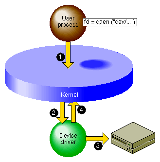
Before a user process can use a kernel-controlled device, the process must open the device as a file. A high-level overview of this process, as it applies to a character device driver, is shown in Figure 3-1.
The steps illustrated in Figure 3-1 are:
The user process calls the open() kernel function, passing the name of a device special file (see “Device Special Files” in Chapter 2 and the open(2) reference page).
The kernel notes the device major and minor numbers from the inode of the device special file (see “Devices as Files” in Chapter 2). The kernel uses the major device number to select the device driver, and calls the driver's open entry point, passing the minor number and other data.
The device driver verifies that the device is operable, and prepares whatever is needed to operate it.
The device driver returns a return code to the kernel, which returns either an error code or a file descriptor to the process.
It is up to the device driver whether the device can be used by only one process at a time, or by more than one process. If the device can support only one user, and is already in use, the driver returns the EBUSY error code.
The open() interaction on a block device is similar, except that the operation is initiated from the filesystem code responding to a mount() request, rather than coming from a user process open() request (see the mount(1) reference page).
There is also a close() interaction so a process can terminate its connection to a device.
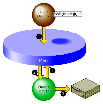
After the user process has successfully opened a character device, it can request control operations. Figure 3-2 shows an overview of this operation.
The steps illustrated in Figure 3-2 are:
The user process calls the ioctl() kernel function, passing the file descriptor from open and one or more other parameters (see the ioctl(2) reference page).
The kernel uses the major device number to select the device driver, and calls the device driver, passing the minor device number, the request number, and an optional third parameter from ioctl().
The device driver interprets the request number and other parameter, notes changes in its own data structures, and possibly issues commands to the device.
The device driver returns an exit code to the kernel, and the kernel (then or later) redispatches the user process.
Block device drivers are not asked to provide a control interaction. The user process is not allowed to issue ioctl() for a block device.
The interpretation of ioctl request codes and parameters is entirely up to the device driver. For examples of the range of ioctl functions, you might review some reference pages in volume 7, for example, termio(7) , ei(7) , and arp(7P) .
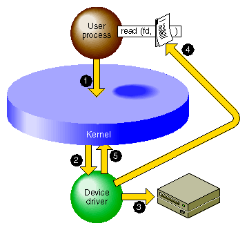
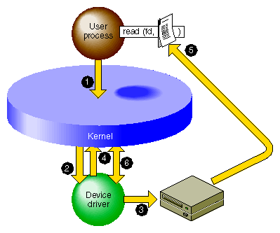
Figure 3-3 shows a high-level overview of data transfer for a character device driver that uses programmed I/O.
The steps illustrated in Figure 3-3 are:
The user process invokes the read() kernel function for the file descriptor returned by open() (see the read(2) and write(2) reference pages).
The kernel uses the major device number to select the device driver, and calls the device driver, passing the minor device number and other information.
The device driver directs the device to operate by storing into its registers in physical memory.
The device driver retrieves data from the device registers and uses a kernel function to store the data into the buffer in the address space of the user process.
The device driver returns to the kernel, which (then or later) dispatches the user process.
The operation of write() is similar. A kernel-level driver that uses programmed I/O is conceptually simple since it is basically a subroutine of the kernel.
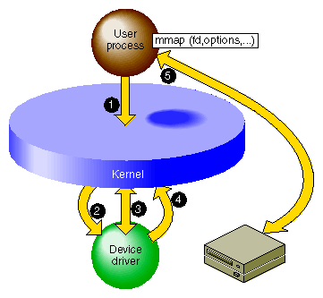
It is possible to allow the user process to perform I/O directly, by mapping the physical addresses of device registers into the address space of the user process. Figure 3-4 shows a high-level overview of this interaction.
The steps illustrated in Figure 3-4 are:
The user process calls the mmap() kernel function, passing the file descriptor from open and various other parameters (see the mmap(2) reference page).
The kernel uses the major device number to select the device driver, and calls the device driver, passing the minor device number and certain other parameters from mmap().
The device driver validates the request and uses a kernel function to map the necessary range of physical addresses into the address space of the user process.
The device driver returns an exit code to the kernel, and the kernel (then or later) redispatches the user process.
The user process accesses data in device registers by accessing the virtual address returned to it from the mmap() call.
Memory mapping can be supported only by a character device driver. (When a user process applies mmap() to an ordinary disk file, the filesystem maps the file into memory. The filesystem may call a block driver to transfer pages of the file in and out of memory, but to the driver this is no different from any other read or write call.)
Memory mapping by a character device driver has the purpose of making device registers directly accessible to the process as memory addresses. A memory-mapping character device driver is very simple; it needs to support only open(), mmap(), and close() interactions. Data throughput can be higher when PIO is performed in the user process, since the overhead of the read() and write() system calls is avoided.
Silicon Graphics device drivers for the VME and EISA buses support memory mapping. This enables user-level processes to perform PIO to devices on these buses. Character drivers for the PCI bus are allowed to support memory mapping.
It is possible to write a kernel-level driver that only maps memory, and controls no device at all. Such drivers are called pseudo-device drivers. For examples of psuedo-device drivers, see the prf(7) and imon(7) reference pages.
Block devices and block device drivers normally use DMA (see “Direct Memory Access” in Chapter 1). With DMA, the driver can avoid the time-consuming process of transferring data between memory and device registers. Figure 3-5 shows a high-level overview of a DMA transfer.
The steps illustrated in Figure 3-5 are:
The user process invokes the read() kernel function for a normal file descriptor (not necessarily a device special file). The filesystem (not shown) asks for a block of data.
The kernel uses the major device number to select the device driver, and calls the device driver, passing the minor device number and other information.
The device driver uses kernel functions to create a DMA map that describes the buffer in physical memory; then programs the device with target addresses by storing into its registers.
The device driver returns to the kernel after telling it to put to sleep the user process that called the driver.
The device itself stores the data to the physical memory locations that represent the buffer in the user process address space. While this is going on, the kernel may dispatch other processes.
When the device presents a hardware interrupt, the kernel invokes the device driver. The driver notifies the kernel that the user process can now resume execution. It resumes in the filesystem code, which moves the requested data into the user process buffer.
DMA is fundamentally asynchronous. There is no necessary timing relation between the operation of the device performing its operation and the operation of the various user processes. A DMA device driver has a more complex structure because it must deal with such issues as
making a DMA map and programming a device to store into a buffer in physical memory
blocking a user process, and waking it up when the operation is complete
handling interrupts from the device
the possibility that requests from other processes can occur while the device is operating
the possibility that a device interrupt can occur while the driver is handling a request
The reward for the extra complexity of DMA is the possibility of much higher performance. The device can store or read data from memory at its maximum rated speed, while other processes can execute in parallel.
A DMA driver must be able to cope with the possibility that it can receive several requests from different processes while the device is busy handling one operation. This implies that the driver must implement some method of queuing requests until they can be serviced in turn.
The mapping between physical memory and process address space can be complicated. For example, the buffer can span multiple pages, and the pages need not be in contiguous locations in physical memory. If the device does not support scatter/gather operations, the device driver has to program a separate DMA operation for each page or part of a page—or else has to obtain a contiguous buffer in the kernel address space, do the I/O from that buffer, and copy the data from that buffer to the process buffer. When the device supports scatter/gather, it can be programmed with the starting addresses and lengths of each page in the buffer, and read and write into them in turn before presenting a single interrupt.
When a device can produce hardware interrupts, its kernel-level device driver has two distinct logical parts, called the “upper half” and the “lower half” (although the upper “half” is usually much more than half the code).
The upper half of a driver comprises all the parts that are invoked as a result of user process calls: the driver entry points that execute in response to open(), close(), ioctl(), mmap(), read() and write().
These parts of the driver are always called on behalf of a specific process. This is referred to as “having user context,” which means that the entry point is executed under the identity of a specific process. In effect, the driver code is a subroutine of the user process.
Upper half code can request kernel services that can be delayed, or “sleep.” For example, code in the upper half of a driver can call kmem_alloc() to request memory in kernel space, and can specify that if memory is not available, the driver can sleep until memory is available. Also, code in the upper half can wait on a semaphore until some event occurs, or can seize a lock knowing that it may have to sleep until the lock is released.
In each case, the entire kernel does not “sleep.” The kernel marks the user process as blocked, and dispatches other processes to run. When the blocking condition is removed—when memory is available, the semaphore is posted, or the lock is released—the driver is scheduled for execution and resumes.
The lower half of a driver comprises the code that is called to respond to a hardware interrupt. An interrupt can occur at almost any time, including large parts of the time when the kernel is executing other services, including driver upper and lower halves.
The kernel is not in a known state when executing a driver lower half, and there is no process context. In conventional UNIX systems and in previous versions of IRIX, the lack of user context meant that the lower-half code could not use any kernel service that could sleep. Because of this restriction, you will find that the reference pages for driver kernel services always state whether the service can sleep or not—a service that might sleep could never be called from an interrupt handler.
Starting with IRIX 6.4, the IRIX kernel is threaded; that is, all kernel code executes under a thread identity. When it is time to handle an interrupt, a kernel thread calls the driver's interrupt handler code. In general this makes very little difference to the design of a device driver, but it does mean that the driver lower half has an identity that can sleep. In other words, starting with IRIX 6.4, there is no restriction on what kernel services you can call from driver lower-half code.
In all systems, an interrupt handler should do as little as possible and do it as quickly as possible. An interrupt handler will typically get the device status; store it where the top-half code expects it; possibly post a semaphore to release a blocked user process; and possibly start the next I/O operation if one is waiting.
Each half has its proper kind of work. In general terms, the upper half performs all validation and preparation, including allocating and deallocating memory and copying data between address spaces. It initiates the first device operation of a series and queues other operations. Then it waits on a semaphore.
The lower half verifies the correct completion of an operation. If another operation is queued, it initiates that operation. Then it posts the semaphore to awaken the upper half, and exits.
IRIX allows for “layered” device drivers, in which one driver operates the actual hardware and the driver at the higher layer presents the programming interface. This approach is implemented for SCSI devices: actual management of the SCSI bus is delegated to a set of Host Adapter drivers. Drivers for particular kinds of SCSI devices call the Host Adapter driver through an indirect table to execute SCSI commands. SCSI drivers and Host Adapter drivers are discussed in detail in Chapter 16, “SCSI Device Drivers”.
A block device driver is called indirectly, from the filesystem, and it is not allowed to support the ioctl() entry point. In some cases, block devices can also be thought of as character devices. For example, a block device might return a string of diagnostic information, or it might be sensitive to dynamic control settings.
It is possible to support both block and character access to a device: block access to support filesystem operations, and character access in order to allow a user process (typically one started by a system administrator) to read, write, or control the device directly.
For example, the Silicon Graphics disk device drivers support both block and character access to disk devices. This is why you can find every disk device represented as a block device in the /dev/dsk directory and again as a character device in /dev/rdsk (“r” for “raw,” meaning character devices).
All but a few Silicon Graphics computers have multiple CPUs that execute concurrently. The CPUs share access to the single main memory, including a single copy of the kernel address space. In principle, all CPUs can execute in the kernel code simultaneously. In principle, the upper half of a device driver could be entered simultaneously by as many different processes are there are CPUs in the system (up to 36 in a Challenge or Onyx system).
A device driver written for a uniprocessor system cannot tolerate concurrent execution by multiple CPUs. For example, a uniprocessor driver has scalar variables whose values would be destroyed if two or more processes updated them concurrently.
In versions previous to IRIX 6.4, IRIX made special provision to support uniprocessor character drivers in multiprocessors. It forced a uniprocessor driver to use only CPU 0 to execute calls to upper-half code. This ensured that at most one process executed in any upper half at one time. And it forced interrupts for these drivers to execute on CPU 0. These policies had a detrimental effect on driver and system performance, but they allowed the drivers to work.
Beginning with IRIX 6.4, there is no special provision for uniprocessor drivers in multiprocessor systems. You can write a uniprocessor-only driver and use it on a uniprocessor workstation but you cannot use the same driver design on a multiprocessor.
It is not difficult to design a kernel-level driver to execute safely in any CPU of a multiprocessor. Each critical data object must be protected by a lock or semaphore, and particular techniques must be used to coordinate between the upper and lower halves. These techniques are discussed in “Designing for Multiprocessor Use” in Chapter 7.
When you have made a driver multiprocessor-safe, you compile it with a particular flag value that IRIX recognizes. For example, drivers are sometimes compiled for Origin2000 systems with the -DSN and -DSN0 flags. Multiprocessor-safe drivers work properly on uniprocessor systems with very little, if any, extra overhead.
Some drivers are needed whenever the system is running, but others are needed only occasionally. IRIX allows you to create a kernel-level device driver or STREAMS driver that is not loaded at boot time, but only later when it is needed.
A loadable driver has the same purposes as a nonloadable one, and uses the same interfaces to do its work. A loadable driver can be configured for automatic loading when its device is opened. Alternatively it can be loaded on command using the ml program (see the ml(1) and mload(4) reference pages).
A loadable driver remains in memory until its device is no longer in use, or until the administrator uses ml to unload it. A loadable driver remains in memory indefinitely, and cannot be unloaded, unless it provides a pfxunload() entry point (see “Entry Point unload()” in Chapter 7).
There are some small differences in the way a loadable driver is compiled and configured (see “Configuring a Loadable Driver” in Chapter 9).
One operational difference is that a loadable driver is not available in the miniroot, the standalone system administration environment used for emergency maintenance. If a driver might be required in the miniroot, it can be made nonloadable, or it can be configured for “autoregistration” (see “Registration” in Chapter 9).
