The DIVO XIO option board provides broadcast-quality video input and output for deskside and server workstations that accept XIO boards. Supporting the SMPTE 259 10-bit digital video standard, it fully integrates video into SGI workstation and server environments.
The DIVO option also provides transparent color space conversion between the YCbCr and RGB color spaces. The DIVO option board can be genlocked to an external digital or analog sync signal, and provides loopthrough to allow genlocking of other video equipment. The DIVO option provides built-in lossless compression (Rice compression), which results in an average 2:1 compression ratio, while maintaining bit-accurate data.
The DIVO-DVC option board has all the functionality of the DIVO option, but also supports DVCPRO, and DV video coding and decoding. The DIVO-DVC option consists of the DIVO base board and two factory-installed daughterboards.
Both options utilize one XIO slot and provide independent dual-link 10-bit serial digital component input and output ports. Depending on the system type, multiple DIVO or DIVO-DVC option boards can be installed on a system for video server applications.
The DIVO and DIVO-DVC options have no direct physical connection with the graphics board set, unlike some previous SGI video boards, such as Sirius Video. Any transfers to or from graphics must go through memory: DIVO has a CCIR 601 dual-link input to memory, and a CCIR 601 dual-link output from memory. Low-latency CCIR 601 output from graphics requires the GVO option board in addition; GVO is a daughterboard for the DG5 board, which is part of the Onyx2 InfiniteReality or Reality graphics board set.
This chapter consists of these sections:
The DIVO and DIVO-DVC options include these features:
dual-link 10-bit serial digital video (SMPTE 259) streaming to and from system memory
serial digital transport interface (SDTI; SMPTE 305) streaming to and from system memory
transparent color-space conversion between YUV and RGB
lossless built-in (Rice) compression and decompression using adaptive entropy coding that retains bit-accurate data with approximately 2:1 compression
flexible data-packing capability to facilitate easy integration to OpenGL component packing methods
unadjusted system time/media stream count (UST/ MSC) hardware-supported audio/video synchronization mechanisms
low latency in video transfers to or from system memory (typically less than one frame)
support for fields and frames
encoding through the in pipe and decoding through the out pipe
AES3-1992 (AES/EBU) embedded audio and ancillary data (SMPTE 272M) with up to 24-bit precision and a sample rate of 48 KHz; up to 4 channels output and 16 channels input
vertical interval time code (VITC) extraction and insertion recorded in the subcode and video auxiliary regions
SDTI multiplexing and demultiplexing via a dmIC API
hardware error detection and handling (EDH) and link autophasing
for each video pipe, two channels of input and output trigger signal pairs based on the general-purpose interface (GPI)
support for the Orion graphical V-LAN control utility
output genlocking
The DIVO and DIVO-DVC option boards support video and audio data transfers to and from system memory only. You can view the video in real time on the Onyx2 and Onyx 3000 workstations using the OpenGL interface to copy video images to graphics. The DIVO and DIVO-DVC options support a wide variety of packing formats to facilitate easy integration of video in graphics; Appendix C, “Pixel Packings and Color Spaces ”, explains these packings.
For controlling videotape recorders, you can use a direct RS-422 connection to the deck with third-party software, or an RS-422 V-LAN controller option and V-LAN software from SGI with the on-board GPI triggering mechanism.
The DIVO and DIVO-DVC options are fully integrated into the SGI Digital Media Library interfaces. The Video Library (VL) API has been enhanced to support some of its advanced features.
In addition to the features summarized in “DIVO and DIVO-DVC Features”, the DIVO-DVC option provides DV video coding and decoding. For explanations of the DVCPRO and DV standards, see Appendix F, “DV and DVCPRO Standards”.
The option consists of the DIVO option board, which can manipulate digital video, including Rice lossless compression and decompression, and two daughterboards. With its speed of 25 Mbps, the DIVO-DVC option provides a flexible and cost-effective way to accomplish a wide range of video projects.
The DIVO-DVC option supports 4:1:1 sampling, which yields a 5:1 compression ratio, for both NTSC and PAL. The DIVO-DVC option also supports 4:2:0 PAL for the DV video formats. Audio processing for DV and DVCPRO is done via a dmAC; Chapter 3, “Audio Data Conversion ”, explains the procedure.
Despite its tape-oriented technology, DVCPRO, like DV, is an open format that is also designed for use with nonlinear editors and server-based systems. A 4X transfer speed record and play capability is possible for DVCPRO and DV, using SDTI; the mechanism is explained in “Programming the DIVO/DIVO-DVC Board for SDTI” in Chapter 2 in Chapter 2, “Programming DIVO and DIVO-DVC”.
VL-based sample applications, such as divo_vitc, divo_ee, divo_memtovid, divo_vidtomem, divo_videowarp, divo_vidtotex, inline.c, and vflip, are included with the DIVO and DIVO-DVC options in the directory /usr/share/src/dmedia/video/DIVO/.
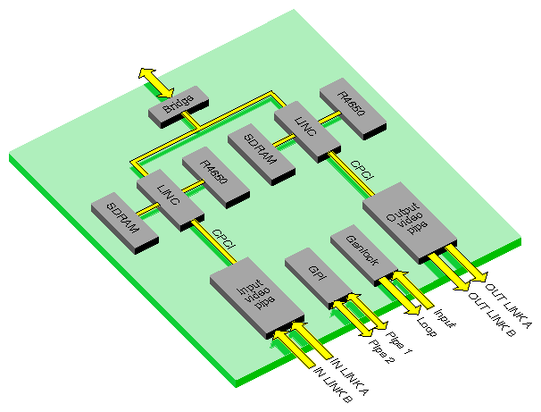
Figure 1-1 is a top-level diagram of the DIVO board. Each DIVO board has two independent pipes, each with its own dedicated R4650 processor and SDRAM.
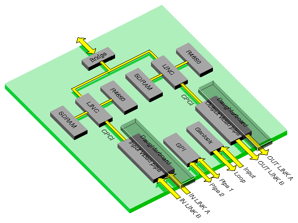
Figure 1-2 is a top-level diagram of the DIVO-DVC board. Each DIVO-DVC board has two independent pipes, each with its own dedicated R4650 processor and SDRAM, and two identical daughterboards that provide DVC encoding and decoding.
The DVC decode card can decode DVCPRO- or DVC-formatted data stored on disk as a digital interface format (DIF) file. After decoding, the audio and video are encoded into a SMPTE 272-compliant audio/video serial stream.
DVCPRO 625-line rate data is processed as 4:1:1 data; in DVC, it is processed as 4:2:0 data. Thus, the DVCPRO superblock structure is similar to that for 525-line rate data, but the two formats are not compatible. Also, for DVCPRO, only 48 KHz audio is encoded.
Besides the sampling patterns 4:4:4 and 4:2:2, the DIVO-DVC board is also capable of 4:1:1 and 4:2:0 sampling. Details are in “4:1:1 Sampling (DIVO-DVC Only)” in Appendix C and “4:2:0 Sampling (DIVO-DVC Only)” in Appendix C, respectively, in Appendix C, “Pixel Packings and Color Spaces ”.
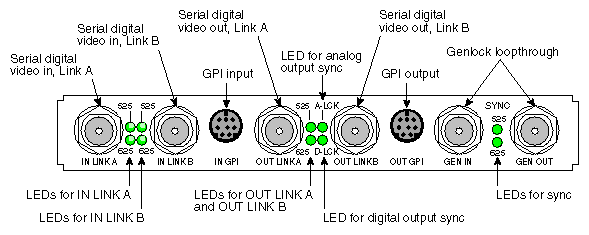
Figure 1-3 shows features of the DIVO/DIVO-DVC I/O panel. Although the board is installed vertically in the chassis, Figure 1-3 shows the panel sideways to facilitate reading of the connector and LED labels.
Table 1-1 summarizes DIVO/DIVO-DVC board external connectors that interface with video equipment.
Table 1-1. Interface for Video Equipment
Connector | Format | Use |
|---|---|---|
Serial digital video input from digital tape deck or other recording device. Conforms to SMPTE 259M for component video, SMPTE 272M for embedded audio, and SMPTE 266M for DVITC. Both inputs autophased. | ||
OUT LINK A, OUT LINK B | 10-bit CCIR 601-2 | Serial digital video output to digital tape deck or other recording device. Conforms to SMPTE 259M for component video, SMPTE 272M for embedded audio, and SMPTE 266M for DVITC. Note: The transfer mode (packing format) selected determines LINK A and LINK B usage, as explained in Table A-3 and Table A-4 in Appendix A, “DIVO/DIVO-DVC I/O Panel Connectors” . |
75-ohm BNC | External analog sync source ( precision time base or other source of house sync) or analog loopthrough. | |
75-ohm BNC | External reference loop out; passive loopthrough for genlock input with buffered signal to workstation. Note: If you attach a cable to one GEN connector, you must attach either another cable to other equipment accepting analog sync or a 75-ohm BNC terminator to the other GEN connector. | |
8-pin mini-DIN | General Purpose Interface for each video port; frame-accurate event triggering to or from source or destination (tape deck or digital recorder). Configurable for switch closure (factory setting) or current sense operation. |
See Appendix A, “DIVO/DIVO-DVC I/O Panel Connectors”, for technical details of the connectors, including GPI pinouts.
Table 1-2 summarizes the function of the LEDs on the panel.
LED | Purpose |
|---|---|
Leftmost LEDs between IN LINK A and IN LINK B (525 and 625) | Top LED lights when valid 525-line serial digital signal detected on IN LINK A. Bottom LED lights when valid 625-line serial digital signal detected on IN LINK A. |
Rightmost LEDs between IN LINK A and IN LINK B (525 and 625) | Valid 525-line (top LED) or 625-line (bottom LED) serial digital signal detected on |
Leftmost LEDs between OUT LINK A and OUT LINK B (525 and 625) | Valid 525-line (top LED) or 625-line (bottom LED) serial digital signal detected on OUTLINK A and OUT LINK B; these outputs are locked together, regardless of whether OUT LINK B is used. |
A-LCK | Output is locked to an analog source: standalone, genlock (to another sync source), or free run. |
D-LCK | Output is locked to a digital source (IN LINK A or IN LINK B). |
SYNC 525 and 625 | Valid 525-line sync source (top LED) or 625-line sync source (bottom LED) detected. |
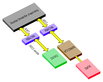
Figure 1-4 diagrams how the DIVO and DIVO-DVC option boards interact with other workstation components.
The DIVO and DIVO-DVC options each have two independent 10-bit serial digital video ports for equipment that complies with the CCIR 601-2 standard. The ports can be configured for 4:4:4:4 or 4:2:2:4 in d ual-link mode, or 4:2:2 in single-link mode where alpha is ignored.
Each port consists of two unidirectional interconnections, Link A and Link B:
The video format selected determines Link A and Link B usage. For more information, see the following standards, which contain provisions for video signals:
CCIR 601-2: Encoding Parameters of Digital Television for Studios (4:2:2 component video signals, single link)
ANSI/SMPTE 125M-1992: Television—Component Video Signal 4:2:2—Bit-Parallel Digital Interface
SMPTE Recommended Practice (RP) 175-1993: Digital Interface for 4:4:4:4 Component Video Signals (Dual Link)
SMPTE 259M-1993: Television—10-Bit 4:2:2 Component and 4fsc NTSC composite Digital Signals—Serial Digital Interface
SMPTE RP 157-1990: Key Signals
SMPTE 272M: Television - Formatting AES/EBU Audio and Auxiliary Data into Digital Video Ancillary Data Space
Four color spaces are native to the DIVO/DIVO-DVC option: full-range RGBA, compressed range RGB (RP-175), CCIR601, and full-range YUV. The video interface supports only RP-175 and CCIR 601-2. The memory interface supports all four color spaces. See “Color Spaces ” in Appendix C for an explanation of full- and compressed-range color spaces.
The DIVO/DIVO-DVC option uses the Gennum GF9105 component digital transcoder. The GF9105 uses 13-bit multiplier coefficients and provides up to 13-bit output resolution, allowing for transparent color-space conversion between YUV and RGB.
The DIVO/DIVO-DVC option supports the transmission of audio, subcode data, and compressed video packets associated with DV-based 25-Mbps data structures for 525/60 and 625/50 systems, including faster than real-time transfers and multichannel transmission.
The section “Programming the DIVO/DIVO-DVC Board for SDTI” in Chapter 2 explains how to program the DIVO/DIVO-DVC option board for SDTI. For more information on SDTI and on SDTI with embedded DV, refer to the most recent editions of the following:
Proposed SMPTE standard 305M for Television—Serial Data Transport Interface
Proposed SMPTE Standard 306M for Television Digital Recording—6.35-mm Type D-7 Component Format, Video Compression at 25 Mb/s, 525/60 and 625/50
Proposed SMPTE Standard 314M for Television—Data Structure for DV-Based Audio, Data and Compressed Video - 25 and 50 Mb/s
SMPTE's web site is http://www.smpte.org/.
The GF9105 transcoder provides interpolation and decimation filtering between the 4:2:2:4 and 4:4:4:4 sampling rates. Both interpolation and decimation operations are fully compliant with the CCIR 601-2 standard.
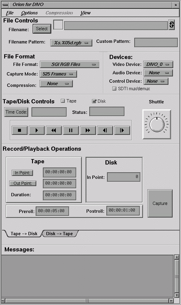
The DIVO/DIVO-DVC option supports the SGI Orion graphical utility for tapedeck control and for capture and playback. Figure 1-5 shows the main window.
The Orion utility offers
standard deck controls: rewind, fast forward, stop, play, and so on
editing controls, such as in point, out point, preroll, postroll
deck shuttle control
a variety of video file formats including QuickTime
capture and playback in both field and frame mode
support for synchronized audio and video capture and playback
V-LAN triggering for capture and playback
support for multiple DIVO/DIVO-DVC boards and multiple V-LAN devices

Note: If “Audio Device” is set to Default in the video control panel (vcp) and the DIF stream contains audio data, audio is played out on the default audio devices while Video Decode/Playout is in progress.
The Orion utility is at /usr/dmedia/bin/DIVO/orion. The utility is fully described in its man page, orion(1M) .
The DIVO/DIVO-DVC option provides one 4-channel wide input device and one four-channel wide output device, which are compliant with the SMPTE 272M standard. Applications can open either device as two or four channels. Unused output channels are set to zero; unused input channels are discarded. DIVO/DIVO-DVC audio supports a sample rate of 48 KHz. It supports 20- and 24-bit word sizes. Access to the audio is through the Audio Library (AL) interfaces specified in the Digital Media Programming Guide.
