This appendix summarizes hardware specifications for the DIVO and DIVO-DVC option boards, in these sections
Table A-1 summarizes return loss for the IN LINK A, IN LINK B, and GEN IN connectors.
Table A-1. Return Loss for DIVO/DIVO-DVC Video and Genlock Channels
Channel | Value |
|---|---|
IN LINK A, IN LINK B | > 15 dB @ 270 MHz |
GEN IN | > 40 dB @ 6 MH |
Table A-2 summarizes output characteristics for the OUT LINK A and OUT LINK B connectors.
Table A-2. Characteristics for DIVO/DIVO-DVC Digital Video Out Channels
Characteristic | Value |
|---|---|
Amplitude | 800 mV +/-10% |
Rise/fall time | .75 nsec to 1.5 nsec |
Overshoot | <10% p-p |
Alignment jitter | <740 ps p-p |
Table A-3 summarizes the use of LINK A and LINK B connectors for 4:2:2:4 mode. If LINK B is not used in 4:2:2:4 format, the resulting format is 4:2:2. The LINK A connector carries 10-bit wide UVY information; the LINK B connector carries 10-bit alpha. Usage is similar for 10-bit RGBA.
Table A-3. Usage for LINK A and LINK B in 4:2:2:4 Mode
Sample | LINK A | LINK B |
|---|---|---|
0 | Cb0 | x |
1 | Y0 | A0 |
2 | Cr0 | x |
3 | Y1 | A1 |
Table A-4 summarizes the use of LINK A and LINK B connectors for 4:4:4:4 mode. The LINK A connector carries a 4:2:2 sampled portion of 10-bit wide UVY; the LINK B connector carries the remaining 10-bit UV samples and 10-bit alpha. Usage is similar for 10-bit RGBA.
Table A-4. Usage for LINK A and LINK B in 4:4:4:4 Mode
Sample | LINK A | LINK B |
|---|---|---|
0 | Cb0 | Cb1 |
1 | Y0 | A0 |
2 | Cr0 | Cr1 |
3 | Y1 | A1 |
The GEN OUT and GEN IN connectors make up a passive genlock loopthrough connection. If you attach a cable to one GEN connector, you must attach to the other GEN connector either a 75-ohm BNC terminator or a cable to other equipment accepting analog sync. If another cable is connected, it must ultimately be terminated.
For each video pipe, the General Purpose Interface (GPI) provides two channels of input and output trigger signal pairs. This section consists of the following:
The panel on the DIVO and DIVO-DVC option boards has two GPI connectors, each associated with one of the serial digital video ports (two transmit and two receive channels each). Figure A-1 points out the GPI connectors on the DIVO/DIVO-DVC panel.
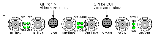
Figure A-2 shows pinouts for the GPI; the information is applicable for both the IN GPI and OUT GPI connectors. In this figure, CCT denotes contact closure transmit, and CCR denotes contact closure receive.
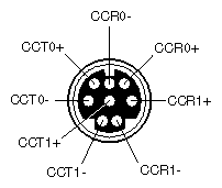
Each +/- signal pair of the same name applies to one channel of either a receive or transmit optical device. Table A-5 gives the meaning of the pins in Figure A-2.
Pin | Symbol | Name | Channel |
|---|---|---|---|
8 | CCT0+ | Contact Closure Transmit + | 0 |
4 | CCT0- | Contact Closure Transmit - | 0 |
5 | CCT1+ | Contact Closure Transmit + | 1 |
2 | CCT1- | Contact Closure Transmit - | 1 |
6 | CCR0+ | Contact Closure Receive + | 0 |
7 | CCR0- | Contact Closure Receive - | 0 |
3 | CCR1+ | Contact Closure Receive + | 1 |
1 | CCR1- | Contact Closure Receive - | 1 |
GPI contact closure transmit (CCT) outputs use an optically coupled solid-state relay (SSR) to provide a means of electrical isolation for destination equipment. The GPI transmitter is triggered by setting VL_GPI_STATE (see “Using VL_GPI_STATE” in Chapter 2 in Chapter 2, “Programming DIVO and DIVO-DVC”), which forward-biases the internal LED, which in turn drives the output MOSFET, closing the contacts of the SSR.
When the GPI trigger is off, a high resistance exists between the CCT+/- terminals. When the GPI is on (triggered by setting VL_TRANSFER_TRIGGER to VL_TRIGGER_GPI (see “Using VL_TRANSFER_TRIGGER” in Chapter 2 in Chapter 2, “Programming DIVO and DIVO-DVC”), a low resistance exists between the terminals.
Figure A-3 and Table A-6 show electrical specifications for the GPI transmitter.
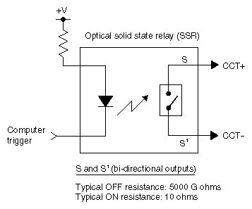
Table A-6. GPI Transmitter Electrical Specifications
Parameter | Value |
|---|---|
On resistance | 10 ohms typical, 15 ohms maximum |
Off resistance | 5000 G ohms |
Current limit | 360 mA typical, 460 mA maximum |
Output capacitance | 60 pF |
Continuous DC load current | 180 mA |
Output power dissipation | 600 mW |
Isolation voltage | 3750 V rms |
The GPI transmitter can be interfaced to the destination equipment by tying the CCT- terminal to GND and using the CCT+ terminal as a current sink. The input device can consist of a logic device with active pullup, an optoisolator LED with series-limiting resistor, or relay primary with series-limiting resistor.
The GPI transmitter's logic sense can be swapped (inverted) by tying the CCT+ terminal to the logic power supply (VCC) of the destination equipment and using the CCT- terminal to drive the input of the receiving device.
GPI contact closure receive (CCR) inputs use an optical isolator device to provide a means of electrical isolation from source equipment. The device consists of a bidirectional input LED optically coupled to a bipolar transistor. A voltage pulse applied across the CCR+/- pins causes the LED to become forward-biased and to produce a GPI trigger to the computer.
Figure A-4 shows electrical specifications for the GPI receiver.
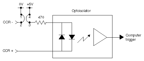
Table A-7 summarizes electrical specifications for the GPI receiver optoisolator.
Table A-7. GPI Receiver Input Optoisolator Electrical Specifications
Parameter | Value |
|---|---|
Forward voltage (VF) | 1.55 V, 1.2 V typical (IF = 10 mA) |
Continuous forward current (IF) | 30 mA |
Peak forward current | 1000 mA (10 us duration, 1% DC) |
Reverse current (IR) | 0.1 uA, 100 uA maximum (VR = 6 V) |
Isolation surge voltage (V10) | 2500 VACRMS (t = 1 min) |
The +5 V power supply and ground of the DIVO/DIVO-DVC board are not electrically isolated from the chassis of the source equipment. The GPI receiver can be interfaced to the source equipment by tying the CCR+ and CCR- terminals across the output terminals of an optoisolator, solid-state relay, or any device that acts like a single-pole contact switch.
The GPI receiver is set to switch closure mode, which creates a digital pulse. A GPI trigger is generated as long as the source switch is closed.
| Note: Polarity of the CCR+/- signals must be observed for the source equipment. |