This appendix illustrates how to attach video equipment to connectors on the DIVO/DIVO-DVC I/O panel and how to use the video control panel vcp to set the option to match your installation.
This appendix explains
Figure B-1 shows connectors on the DIVO/DIVO-DVC I/O panel.
The DIVO/DIVO-DVC panel has two 10-bit digital video input ports (IN LINK A and IN LINK B) for equipment that complies with the CCIR 601 standard. The ports can be configured for 4:4:4:4 or 4:2:2:4 d ual-link mode; for 4:2:2 single-link mode, ignore the alpha:
To set up the option for a digital video source, follow these steps:
Connect a video device to IN LINK A and, if you are using a device for alpha key data, also IN LINK B. If you use only one input, it must be IN LINK A.
-
/usr/sbin/vcp
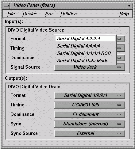
In the Inputs(s): DIVO Digital Video Source section of the control panel vcp for the channel(s) you are using, select the format that matches your equipment, as shown in Figure B-2.
In the Digital Video Source portion of the panel for the channel(s) you are using, select the timing that matches your equipment: CCIR 525 or CCIR 625.
To set up the digital video output, follow these steps:
Connect the video equipment to OUT LINK A and, if you are using a device for alpha key data, also OUT LINK B. If you use only one output, it must be OUT LINK A.
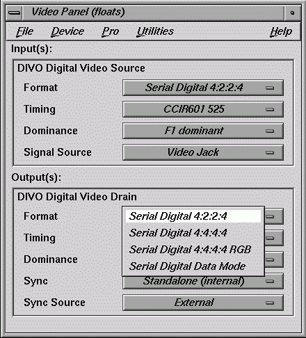
In the Output(s): DIVO Video Drain section of the control panel, select the format that matches your equipment, as shown in Figure B-3.
Select the timing that matches your equipment: CCIR 525 or CCIR 625.
To set field dominance, at the “Input Timing” menu item select “F1 dominant” for the edit to occur on the nominal video field boundary, or “F2 dominant” for the edit to occur on the intervening field boundary. See “Setting Field Dominance” in Chapter 2 for more information on field dominance.
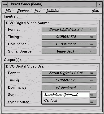
In the Output(s): DIVO Digital Video Drain section of the control panel, select the Sync format that matches your equipment:
standalone (not synced to another device): select Standalone (internal)
output sync to an external source connected to the genlock in: select Genlock
These two choices toggle, as shown in Figure B-4.
To set up the /DIVO-DVC option for an external sync source, follow these steps:
Connect the sync source equipment to one of the following connectors:
the GEN IN BNC on the I/O panel, as diagrammed in Figure B-5.
IN LINK A or IN LINK B (if the device is not already cabled to this connector)
If you are using the same signal for other equipment, attach a BNC cable to the GEN OUT BNC to loop the signal through the board. Make sure the final element in the chain is terminated.
If DIVO/DIVO-DVC is the last element in the sync chain, make sure a terminator is attached to the GEN OUT BNC.
Select the appropriate setting in Output(s): Sync Source:
select External for a device connected to GEN IN
select Digital Input Link A or B if you are syncing to the device attached to IN LINK A or IN LINK B, respectively
Once you have set values in vcp to match your installation, save them; they are written to /usr/etc/video/videod.defaults. Select “Restore Settings” on the video control panel File menu to load the values in this file to vcp.
The last settings saved are automatically loaded every time the system is reinitialized. If the panel is running, current settings are in effect.
| Note: You do not need to open the panel to put its settings into effect. |
You can also use File menu choices to restore the factory defaults and close the panel.


